
Related Manuals for JR Venture CP


Summary of Contents for JR Venture CP
-
Page 1: Assembly Instructions
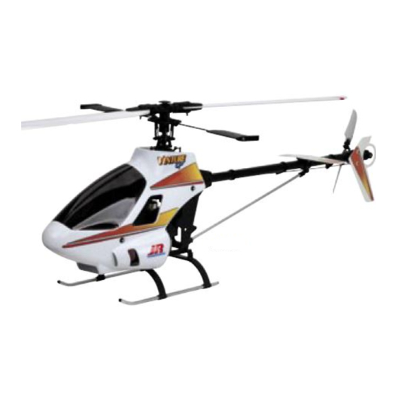
™ ASSEMBLY INSTRUCTIONS VENTURE SPECIFICATIONS Overall Length 44.60'' Tail Rotor Diameter 9.30'' Overall Height 17.20'' Gear Ratio 9.78 : 1 : 5.18 Main Rotor Diameter 49.50'' Gross Weight 7.00–7.50 lb Version 1.0... -
Page 2: Table Of Contents
TABLE OF CONTENTS Section Description Page Section Description Page Introduction ........... . 3 Radio Data Sheet: X-378 Basic Setup . -
Page 3: Introduction
JR heli division parts dealer or the Horizon Service Center directly. The radio controlled model helicopter contained in this kit is not a toy but a sophisticated piece of equipment. -
Page 4: Venture 30 Cp Arf Features
VENTURE 30 CP ARF FEATURES ™ CCPM (Cyclic/Collective Pitch Mixing): Ultra-Low Parts Count More Accurate: Control system play is totaly eliminated Adds reliability and ease of maintenance Simpler: Fewer links to set up and maintain Self-Aligning One-Piece Steel Clutch System More Powerful: Collective has three times the servo power, cyclic has double Offers easy installation and adjustment with exceptional reliability Two-Piece Box Frame System... -
Page 5: Engine Requirements
2. ENGINE REQUIREMENTS (NOT INCLUDED): A .32–.38 R/C helicopter engine A special helicopter-type muffler is also required. Webra 35 AAR Heli Engine (WEBE351) .32–.36 Muffler (JRP960785) HN30C Competition Muffler (KSJ399) Beginner 3D Performance 3. BUILDING SUPPLIES (NOT INCLUDED): The following items are needed to complete the assembly of the JR Venture ™... -
Page 6: Required Tools
4. REQUIRED TOOLS (NOT INCLUDED): Nut Drivers: 4, 5, 7 mm Needle-Nose Pliers Scissors Phillips Screwdriver (DYN2511) X-ACTO Knife Metric Ruler Drill and Drill Bits Crankshaft Locking Tool (RVO1007) Blade Balancer JR Ball Link Sizing Tool Ball Link Pliers Allen Wrenches: (RVO1001) (JRP960219) 1.5, 2.0, 2.5, 3.0 mm... -
Page 7: Hardware Identification
HARDWARE IDENTIFICATION There are many various sizes and shapes of hardware included in this kit. Prior to All of the hardware, screws, nuts, etc., contained in the Venture ™ kit are described assembly, please be careful to identify each screw by matching it to the full size in the following A, B, C manner: screw outlines included in each step. -
Page 8: Tail Boom Installation
TAIL BOOM INSTALLATION Preinstalled Insert the tail boom assembly into the rear of the frame as shown. 3x15 mm Socket Head Bolt (4) 3 mm Lock Nut (4) 3 mm Lock Nut (4) Note: Check to make sure that the belt is not twisted inside the boom prior to insertion. -
Page 9: Tail Boom Brace Installation
TAIL BOOM BRACE INSTALLATION Preassembled 3x15 mm Socket Head Bolt (1) 3x15 mm Socket Head Bolt (2) It may be neccessary to loosen these bolts to reposition the tail brace 3 mm Lock Nut (1) clamp as needed. Tail Brace Clamp U/D 3 mm Lock Nut (2) 3 mm Lock Nut 3 mm Flat Washer (2) -
Page 10: Tail Control Rod Assembly
TAIL CONTROL ROD ASSEMBLY Universal Link Thread link 8 mm onto Tail Control Rod Bushings (3) the end of the control rod. Tail Control Rod Bushings (3) Tail Control Rod 880 mm Tail Control Rod Tube TAIL CONTROL ROD INSTALLATION/HORIZONTAL FIN ATTACHMENT 3x10 mm Socket Head Bolt (2) 2x8 mm Self-Tapping Screw (3) Insert the tail control rod assembly into... -
Page 11: Engine Mount/Cooling Fan Installation
ENGINE MOUNT/COOLING FAN INSTALLATION 3 mm Lock Nut (4) 3x30 mm Socket Head Bolt (4) Engine Nut 3 mm Lock Nut (4) 3 mm Flat Washer (4) Cooling Fan Assembly Use Threadlock 3 mm Spring Washer (4) *It is recommended that a crankshaft locking tool be used to properly secure the cooling fan assembly to the engine. -
Page 12: Clutch Assembly Attachment
CLUTCH ASSEMBLY ATTACHMENT Continued To insure smooth operation, it is suggested that the clutch assembly the center of the clutch. Note the side-to-side movement (wobble or be checked for trueness (runout) prior to final attachment. Place the run-out). Next loosen the two 3x5 mm clutchbolts and rotate the engine assembly on a flat surface using the engine mount to steady clutch 180°... -
Page 13: Engine Installation
ENGINE INSTALLATION 3x15 mm Socket Head Bolt (4) 3 mm Lock Nut (4) 3 mm Lock Nut (4) Adjust the height and position of the engine as shown so the bottom of the clutch assembly is flush with the bottom of the clutch bell. -
Page 14: Servo Installation
SERVO INSTALLATION 2.6 mm Flat Washer (20) 2.6x12 mm Self-Tapping Screw (20) Left Servo (C) RADIO INSTALLATION SUGGESTIONS Be sure to install four rubber servo grommets and eyelets to each servo prior to installation. When adjusting control rods, be sure to adjust each universal link the same amount so as not to unthread one link too far. -
Page 15: Gyro/Receiver/Switch Harness/Battery Installation
GYRO/RECEIVER/SWITCH HARNESS/BATTERY INSTALLATION It is suggested that both the receiver and gyro amplifier be isolated from vibration by wrapping them in foam, then securing them to the model using double-sided servo tape. Be certain when installing the gyro to the gyro mounting plate that it does not Round Rubber Grommets (2) come in contact with the frame of the helicopter and that the mounting surfaces are free from oil, residue, etc. -
Page 16: Gyro/Receiver/Switch Harness/Battery Installation
GYRO/RECEIVER/SWITCH HARNESS/BATTERY INSTALLATION Continued Wrap the servo leads with the included servo spiral wrap and route as shown. G460T Right Pitch (B) G460T Gyro (Optional) (JRPG460T) Rudder Front Elevator (A) AUX1 GEAR 7 CH 72MHz FM SLIMLINE RUDD RECEIVER ELEV ABC&W INTERFERENCE PROTECTION SYSTEM A I L E... -
Page 17: Understanding Swashplate Control Systems
UNDERSTANDING SWASHPLATE CONTROL SYSTEMS Currently, there are several different types of control systems available on the market. Although the mechanical methods for transferring control to the swashplate vary, the different control systems can be broken down into two categories: One-Servo (Conventional) CCPM (Cyclic/Collective Pitch Mixing) The following is an explanation of the two most popular types of swashplate control. -
Page 18: Understanding Swashplate Control Systems
UNDERSTANDING SWASHPLATE CONTROL SYSTEMS (CONTINUED) 120 Three-Servo CCPM Swashplate Mixing (Venture 30 CP) The JR 120° CCPM or Cyclic/Collective Pitch Mixing, system offers the user a control system that can accomplish the same control inputs as the One-Servo standard system mentioned above, but with increased precision and reduced complexity. As with the One-Servo system, the JR CCPM system utilizes three servos for the three main controls: aileron (roll), elevator(pitch) and collective. -
Page 19: How Jr 120 Ccpm Works
HOW JR 120 CCPM WORKS JR 120° Three-Servo CCPM relies on the radio’s special CCPM swashplate mixing, rather than a conventional mechanical mixer that is utilized to achieve the same results. The radio’s 120° Three-Servo CCPM function automatically mixes the three servos to provide the correct mixing inputs for aileron (roll), elevator (pitch), and collective. -
Page 20: Ccpm Software Activation And Initial Adjustment
CCPM SOFTWARE ACTIVATION AND INITIAL ADJUSTMENT 1. JR XP652/XP662 SYSTEMS The following activation and setup procedure should be used for all JR XP652 and XP662 systems. Please note that the XF622 and XP642 6-channel systems do not have the required CCPM software and therefore cannot be activated by the Horizon Service Center. Prior to activating the CCPM function, it is first suggested that the Data Reset function be performed to reset the desired model number to be used back to the factory default settings. - Page 21 CCPM SOFTWARE ACTIVATION AND INITIAL ADJUSTMENT (CONTINUED) 2. JR XP8103/XP8103DT SYSTEMS The following activation and setup procedure should be used for all JR XP8103 and XP8103DT (digital trim) systems. Note: Some early XP8103 systems will require the activation of the CCPM software through the Horizon Service Center. It’s easy to identify if your system has the CCPM function activated by identifying if the “SWASH TYP”...
- Page 22 CCPM SOFTWARE ACTIVATION AND INITIAL ADJUSTMENT (CONTINUED) 3. JR 10 SERIES SYSTEMS The following activation and setup procedure should be used for all JR PCM10, 10S, 10SX, 10SXI, and 10X systems. Prior to activating the CCPM function, it is first suggested that a Data Reset function be performed to reset the desired model number to be used back to the factory default settings.
-
Page 23: Ccpm Software Activation And Initial Adjustment
CCPM SOFTWARE ACTIVATION AND INITIAL ADJUSTMENT (CONTINUED) 4. JR X-378 SYSTEMS The following activation and setup procedures should be used for all JR X-378 systems. Prior to activating the CCPM function, it is first suggested that the Data Reset function be performed to reset the desired model number to be used back to the factory default settings. -
Page 24: Important Ccpm Programming Guidelines
IMPORTANT CCPM PROGRAMMING GUIDELINES A. TRAVEL ADJUST It is extremely important that the travel adjustment values for the three CCPM servos (aileron, elevator, AUX 1) be initially set to exactly the same travel value. If the travel value is not similar for each servo, it will create unwanted pitching and rolling of the swashplate during collective pitch inputs. -
Page 25: Ccpm Servo Arm Preparation And Installation
CCPM SERVO ARM PREPARATION AND INSTALLATION It will be necessary to prepare three servo arms as shown in the diagram below. Prior to assembling the servo arms, the servos should be centered as indicated below, and the servo arms 2x10 mm Flat Head Screw (3) test fitted to the servo to insure that the arms will attach to the servo as indicated. -
Page 26: Ccpm Servo Centering With The Sub-Trim Function
CCPM SERVO CENTERING WITH THE SUB-TRIM FUNCTION As mentioned in the previous step, it may be necessary to make minor servo centering adjustments with the use of the Sub-Trim function to achieve the desired servo arm positions. Please refer to your particular radio’s section as listed below or consult your radio instruction manual for more information. -
Page 27: Ccpm Servo Centering With The Sub-Trim Function
CCPM SERVO CENTERING WITH THE SUB-TRIM FUNCTION Continued XP8103, XP8103 WITH DIGTIAL TRIMS 1) With the radio power switch on, press the Up and Down keys simultaneously to enter the Function mode. 2) Press the Up key until “Sub Trim” appears on the screen. 3) Adjust the left (aileron), right (AUX 1), and front (elevator) servos as needed until the servo arm is exactly parallel to the servo as shown when the collective stick is in the center position. -
Page 28: Ccpm Linkage Connection
CCPM LINKAGE CONNECTION Attach the three CCPM servo linkages as shown below. It is important that the exact distances specified below be maintained for each linkage as this is critical to the alignment and neutral position of the swashplate. Please also note the direction of the ball links as shown by the “JR Propo” name imprinted on each ball link. -
Page 29: Checking The Swashplate For Level
CHECKING THE SWASHPLATE FOR LEVEL After the three control linkages have been attached to the swashplate, it will be necessary to check the swashplate to ensure that it is level. To do this, turn on the radio system and place the collective stick in the center position as before. Next, check to make sure that all trim levers and knobs are also in their center position. -
Page 30: Pitch-To-Aileron Mixing Adjustment With Travel Adjust
ADVANCED SETUP: PITCH-TO-AILERON MIXING ADJUSTMENT WITH TRAVEL ADJUST (OPTIONAL) It is very possible that the travel of each servo varies slightly, which can cause the swashplate to be tilted to the left or right when the collective is moved to the extreme high and low pitch positions. This condition is generally more common when standard type servos are used. -
Page 31: Pitch-To-Elevator Mixing Adjustment With Travel Adjust
ADVANCED SETUP: PITCH-TO-ELEVATOR MIXING ADJUSTMENT WITH TRAVEL ADJUST (OPTIONAL) The total travel of each servo can vary slightly, which can also cause the swashplate to be tilted fore and aft when the collective is moved to the extreme high and low pitch positions. This situation can also be corrected if necessary through the use of the Travel Adjustment function. To check pitch-to-elevator mixing, it will first be necessary to position the collective stick in the center position as in the previous steps. -
Page 32: Tail Control Rod Servo Connection
TAIL CONTROL ROD SERVO CONNECTION 2x8 mm Flat Head Screw (1) 2 mm Hex Nut (1) Steel Joint Ball (1) Note: The 4th HD servo arm included in the kit can be Use Blue Threadlock used for the rudder servo. 2 mm Hex Nut Please refer to your gyro’s instructions for... -
Page 33: Throttle Linkage Installation
3-10 THROTTLE LINKAGE INSTALLATION 2x8 mm Flat Head Screw 2 mm Hex Nut Steel Joint Ball Use Blue Threadlock 2x8 mm Flat Head Screw Steel Joint Ball 2 mm Hex Nut 2.3x85 mm Threaded Rod 62.5 mm–65.5 mm THROTTLE ARM/SERVO HORN POSITIONS 90°... -
Page 34: Body Assembly/Canopy Attachment
BODY ASSEMBLY/CANOPY ATTACHMENT Preinstalled Rubber Grommet (4) Trim the shaded area from the windshield as shown. 2.3x8 mm Self Tapping Screw (6) 2.3x8 mm Self-Tapping Screw (6) Body Canopy After trimming, attach the windshild to the body temporarily with tape. Next, drill five 1/16" holes Rubber Grommet (4) through both the windshield and the body and secure using the 2.3x8 mm screws provided. -
Page 35: Decal Attachment
DECAL ATTACHMENT Attach the decals as shown. It is suggested that the parts be cleaned with rubbing alcohol prior to decal attachment. Front Grill Side Grills (X2) -
Page 36: Main Rotor Blade Balancing
MAIN ROTOR BLADE BALANCING Main Rotor Blades Step 1 Step 2 Drinking Glass (2 pcs) Final Static Balancing Spanwise C.G. Balancing To static balance the main rotor blades, either attach each blade to a Place each rotor blade on a sharp edge of a table as “seesaw”... -
Page 37: Optional 3D Control System Setup
OPTIONAL 3D CONTROL SYSTEM SETUP ™ For advanced pilots wanting the best 3D performance from the Venture , please perform the following changes as shown below. A. SWASHPLATE MODIFICATION 2x12 mm Flat Head Screw (2) 2x12 mm Flat Head Screw Remove Ball Spacers (2) Ball Spacer... -
Page 38: Optional 3D Control System Setup
OPTIONAL 3D CONTROL SYSTEM SETUP Continued C. 3D FLYBAR/PADDLE INSTALLATION Remove the current flybar and paddles by removing one paddle and loosening the two 4 mm flybar control arm screws. Use Blue Threadlock Install the special 410 mm 3D flybar and paddles as shown. Check to make sure that the flybar is centered before attaching the paddles. -
Page 39: Radio Data Sheet: Xp652/662 Basic Setup
XP652/XP662 HELI DATA SHEET VENTURE CP BASIC SETUP Modulation S-PCM • Z-PCM • PPM (FM) Model Number ___________________ Venture CP Training Setup Model Name ________________________ CHANNEL THR (1) AIL (2) ELE (3) RUD (4) GER (5) PITCH (6) NORM NORM... -
Page 40: Radio Data Sheet: Xp652/662 3D Setup
XP652/XP662 HELI DATA SHEET VENTURE CP 3D SETUP Modulation S-PCM • Z-PCM • PPM (FM) Model Number ___________________ Venture CP Setup Model Name ________________________ CHANNEL THR (1) AIL (2) ELE (3) RUD (4) GER (5) PITCH (6) NORM NORM NORM... -
Page 41: Radio Data Sheet: X-378 Basic Setup
X-378 HELI DATA SHEET VENTURE CP BASIC SETUP MODEL NO. ____________________________________ Venture CP Training Setup MODEL NAME __________________________________ MODULATION SPCM - ZPCM - PPM ________________ AILE ELEV RUDD OFF • ON AUTO OFF • ON (POS. 1) DUAL-RATE OFF • ON •... -
Page 42: Radio Data Sheet: X-378 3D Setup
X-378 HELI DATA SHEET VENTURE CP 3D SETUP MODEL NO. ____________________________________ Venture CP 3D Setup MODEL NAME __________________________________ MODULATION SPCM - ZPCM - PPM ________________ AILE ELEV RUDD OFF • ON AUTO OFF • ON (POS. 1) DUAL-RATE ADJUST AS NEEDED OFF •... -
Page 43: Radio Data Sheet: Xp8103 Basic Setup
XP8103 HELI DATA SHEET VENTURE CP BASIC SETUP MODEL NO. ____________________________________ MODEL NAME __________________________________ MODULATION SPCM - ZPCM - PPM ________________ AILE ELEV RUDD INH • ACT AUTO INH • ACT (POS. 1) DUAL-RATE Adjust as needed INH • ACT •... -
Page 44: Radio Data Sheet: Xp8103 3D Setup
XP8103 HELI DATA SHEET VENTURE CP 3D SETUP MODEL NO. ____________________________________ MODEL NAME __________________________________ MODULATION SPCM - ZPCM - PPM ________________ AILE ELEV RUDD INH • ACT AUTO INH • ACT (POS. 1) DUAL-RATE Adjust as needed INH • ACT •... -
Page 45: Radio Data Sheet: Pcm10X 3D Setup
10X HELI DATA SHEET MODEL NO. (84) _____________________________________ VENTURE CP 3D SETUP MODEL NAME (81) ___________________________________ MODULATION (85) SPCM-ZPCM-PPM ___________________ THRO AILE ELEV RUDD GEAR PITCH AUX2 AUX3 AUX4 AUX5 REVERSE SW TRAVEL ADJUST Refer to the CCPM section of this manual for proper settings... - Page 46 10X HELI DATA SHEET VENTURE CP INITIAL SETUP CONTINUED • —— —— HOV.SEL THRO • CURVE 100% (18) • TH,TRIM=SLOW HOV.T=CENTER • • -2°Pitch 5°Pitch 10°Pitch • —— —— HOV.SEL • PITCH -10°Pitch 0°Pitch 10°Pitch CURVE • (68) • P,TRIM=CENTER HOV.P=CENTER...
-
Page 47: Final Servo Adjustment And Radio Setup
FINAL SERVO ADJUSTMENT AND RADIO SETUP Now that the radio system is completely installed into the helicopter, it is Pitch Range Settings necessary to check and adjust the following: Flight Application Low Pitch Hovering Pitch High Pitch 1. Servo Direction (Servo Reversing) Mode (Low Stick) (Half Stick) - Page 48 FINAL SERVO ADJUSTMENT AND RADIO SETUP (CONTINUED) It will now be necessary to establish the maximum pitch value B. Throttle Curve Settings required for your application prior to adjustment. For example, if you are Below are several examples of possible throttle curves during various a beginning pilot, then your maximum negative pitch will be -5, and your flight conditions.
-
Page 49: Final Servo Adjustment And Radio Setup
FINAL SERVO ADJUSTMENT AND RADIO SETUP (CONTINUED) 6. Gyro Gain Adjustment (Dual Remote Gain Gyros only) This same adjustment will also be necessary to achieve proper It will be necessary to adjust the “gain” or compensation of the gyro forward flight. Generally, the gyro gain for forward flight will be to create the correct amount of “holding power”... -
Page 50: Final Preflight Check
FINAL PREFLIGHT CHECK Once all assemblies have been completed, please review the following • Insure that all servos are operating smoothly and in the correct suggestions before attempting initial flights. direction. Also verify that there is no binding in the control rods and •... -
Page 51: Advice And Basic Hover Training Practices
ADVICE AND BASIC HOVER TRAINING PRACTICES Flight Training Flight Simulators A model helicopter simulator is highly recommended and is an excellent training aid. Simulators like the CSM V10 will help you learn the orientation and inputs needed to fly a model helicopter, without the risk of damaging your model to learn these same reactions. In general, most beginning pilots find that using an RC simulator prior to their first actual flights with their model increase the speed in which they learn, and also decrease the number of crashes associated with learning to fly. -
Page 52: General Maintenance
GENERAL MAINTENANCE Engine After each day of flying, fully drain the fuel tank. Then, start the engine and let it idle until the engine and the fuel line are completely burned off. It is also suggested that an after-run oil be used to prevent premature engine corrosion. Tail Rotor Belt Periodically check the tension on the tail drive belt (as shown in Step 1-2, page 8) to insure that it has sufficient tension for proper engagement. -
Page 53: Troubleshooting Guide
VENTURE 30 CP TROUBLESHOOTING GUIDE PROBLEM CAUSE CURE Helicopter vibrates excessively a. Rotor blades out of balance Re-balance rotor blades b. Flybar/paddles not centered Re-center flybar on rotor head c. Engine running roughly Re-adjust engine lean/rich settings d. Excessive clutch run out Re-align clutch assembly Engine runs inconsistent a. -
Page 54: Preassembled Components
PREASSEMBLED COMPONENTS The following parts included in your kit are preassembled. When maintenance or repair is necessary, please refer to these sections for disassembly or reassembly procedures. CLUTCH BELL ASSEMBLY Pinion Gear Use Red Threadlock Apply a very thin coat of red threadlock before inserting pinion gear into the start shaft bearing block. -
Page 55: Elevator Arm Assembly
ELEVATOR ARM ASSEMBLY 14.5 mm Long Ball Arm (1) Elevator Arm Bushing (2) Elevator Arm Pin (1) Elevator Arm 3 mm Flat Washer (1) 3 mm Hex Nut (1) Swashplate A Arm 3 mm Hex Nut Elevator Arm Pin 14.5 mm Long Ball Arm 3 mm Flat Washer FUEL TANK ASSEMBLY Trim to a length of 45 mm... -
Page 56: Main Frame Section Assembly
MAIN FRAME SECTION ASSEMBLY Body Mounting Post, 20 mm (4) 3x14 mm Set Screw (4) Install the servo mounting plates as shown. Servo Mounting Plate (10) Main Frame, right 3x14 mm Set Screw (4) Body Mounting Post, 20 mm (4) Main Frame, left Body Mounting Post, 20 mm (4) 3x14 mm Set Screw (4) -
Page 57: Main Frame Clutch/Tail Pinion/Elevator/Fuel Tank
MAIN FRAME CLUTCH/TAIL PINION/ELEVATOR/FUEL TANK INSTALLATION Use Blue Threadlock 3x8 mm Socket Head Bolt (2) 3x15 mm Socket Head Bolt (20) 3 mm Lock Nut (20) Elevator Arm Bushing 32 mm (1) Bearing (L-1910ZZ) (2) 3x8 mm Socket Head Bolt (2) 3 mm Lock Nut (20) Tail Drive Pinion Assembly Elevator Arm Bushing 32mm... -
Page 58: Front Radio Bed/Cooling Shroud Installation
FRONT RADIO BED/COOLING FAN SHROUD INSTALLATION 3x10 mm Socket Head Bolt 2.6x10 mm Self-Tapping Screw 3x10 mm Socket Head Bolt (4) Front Radio Bed Cooling Fan Shroud 2.6x10 mm Self-Tapping Screw (4) -
Page 59: Main Drive Gear/Autorotation Assembly Installation
MAIN DRIVE GEAR/AUTOROTATION ASSEMBLY INSTALLATION 4x4 mm Set Screw (2) Secure the autorotation hub to the main rotor shaft using the 3x22 mm socket head bolt. Next, slide the main shaft collar onto the main rotor shaft. While pulling upward on the main rotor shaft, secure the 3x22 mm Socket Head Bolt (1) main shaft collar to the main rotor shaft using the four 4x4 mm set screws. -
Page 60: Landing Gear Assembly Installation
LANDING GEAR ASSEMBLY INSTALLATION 3x8 mm Socket Head Bolt 3x12 mm Socket Head Bolt 3x8 mm Socket Head Bolt (4) 3x4 mm Set Screw 3 mm Flat Washer (4) Landing Gear Damper (4) Rear Landing Strut 3x4 mm Set Screw (4) 3 mm Flat Washer (4) 3x12 mm Socket Head Bolt Landing Strut (2) -
Page 61: Flybar Control Arm/Seesaw Arm Assembly
FLYBAR CONTROL ARM/SEESAW ARM ASSEMBLY Center Hub 3x16 mm Socket Head Bolt (2) Main Blade Holder (2) 3x16 mm Socket Head Bolt (2) 2x10 mm Flat Head Screw (4) 3 mm Flat Washer (4) 2x12 mm Flat Head Screw (2) Ball Bearing Seesaw 3 mm Flat Washer (4) -
Page 62: Main Blade Holder Assembly
MAIN BLADE HOLDER ASSEMBLY 3x6 mm Self-Tapping Screw (4) Main Blade Bearing Spacer, Inner (2) Main Blade Bearing Spacer, Outer (2) 2x10 mm Flat Head Screw (2) 5x13x4 Shielded Bearing (4) Joint Ball (2) Main Blade Holder (2) 5x13x4 Shielded Bearing (4) 3x6 mm Self-Tapping Screw (4) Joint Ball (2) 2x10 mm Flat Head Screw (2) -
Page 63: Washout Assembly
WASHOUT ASSEMBLY Be careful not to over-tighten the 3x15 mm socket head bolt. If any clearance is detected between the washout arm and the washer base, an 3x15 mm Socket Head Bolt (2) additional nylon washer (t0.13) can be used. 2x10 mm Flat Head Screw (2) Washout Base 3 mm Flat Washer (2) -
Page 64: Tail Pitch Plate Assembly
TAIL PITCH PLATE ASSEMBLY Tail Pitch Link Pin (2) Note the direction of the tail pitch link. There are four holes on one side of the tail pitch link. Tail Pitch Link (2) Tail Pitch Plate The side with four holes is Tail Slide Ring toward the direction pointed by the arrow. -
Page 65: Rotor Head Installation
ROTOR HEAD INSTALLATION 2.6x12 mmSocket Head Bolt (1) Steel Joint Ball (2) 2.6 mm Lock Nut (1) 2 mm Hex Nut (2) 3x20 mmSocket Head Bolt (1) 3 mm Lock Nut (1) 3 mm Flat Washer (1) 2x12 mm Flat Head Screw (2) Rotor Head Assembly 2.6 mm Lock Nut 3 mm Lock Nut... -
Page 66: Flybar Paddle Attachment
4-10 FLYBAR PADDLE ATTACHMENT (TRAINER PADDLES) Flybar Paddle (2) (trainer) 4x6 mm Set Screw Insert Weight (4) (optional) 3 mm Lock Nut 4x6 mm Set Screw (2) Important: Thread each flybar paddle onto the flybar until the threaded tip of the flybar protrudes approximately 5 mm. -
Page 67: Tail Gear Case Preparation
TAIL GEAR CASE PREPARATION Tail Drive Belt 3x8 mm Socket Head Bolt (2) 3x8 mm Socket Head Bolt (2) Tail Pitch Base Tail Output Shaft Bearing (5x13x4) Tail Gear Case L Tail Gear Case R TAIL GEAR CASE ASSEMBLY 3x6 mm Socket Head Bolt 2.6x12 mm Socket Head Bolt (2) 3x6 mm Socket Head Bolt (3) Tail Output Shaft Assembly... -
Page 68: Tail Center Hub Assembly
TAIL CENTER HUB ASSEMBLY 3x3 mm Set Screw (2) 3x3 mm Set Screw (2) 3 mm Lock Nut (2) Be sure to engage the two 3 mm Tail Rotor Center Hub set screws into the hole in the tail output shaft. Use Red Threadlock Tail Blade Holder Bearing (3x8x4) (4) Tail Slide Ring Assembly... -
Page 69: Tail Pitch Control Lever Installation
TAIL PITCH CONTROL LEVER INSTALLATION Snap control lever onto ball. 2x8 mm Flat Head Screw (1) 2x8 mm Socket Head Bolt (1) 2 mm Flat Washer (1) Steel Joint Ball (1) Tail Pitch Control Lever Tail Lever Bushing Steel Joint Ball 2 mm Flat Washer 2x20 mm Socket Head Bolt 2x8 mm Flat Head Screw... -
Page 70: Parts Diagrams/Parts Listings
MAIN ROTOR HEAD ASSEMBLY 984024 960740 960714 970002 960070 960068 960867 960071 980009 970279 980023 997168 980036 980035 996066 981004 980060 981032 980129 980044 980036 981038 980052 970002 970030 980028 980040 980040 997169 996067 981049 980032 980016 980004 960729 980037 Trainer 960060 (510mm) 3D 960057 (410mm) 980135... - Page 71 MAIN ROTOR HEAD ASSEMBLY PARTS PART # DESCRIPTION COMMENTS/ADDITIONAL CONTENTS QUANTITY JRP960729 Flybar Control Arm Flybar Control Arm Steel Joint Balls Flat Head Screw 2x12 mm 2 mm Hex Nuts 4x4 mm Set Screws JRP960060 Flybar 540 mm Flybar 540 mm (Training) JRP996057 Flybar 410 mm Flybar 410 mm (3D)
- Page 72 CONTROL SYSTEM ASSEMBLY 960013 997168 980041 970002 994024 980016 960860 981015 970010 980032 970002/980032 (3D) 997168 980044 970184 980135 980067 997168 960009 980037 980042 970002 970002 980013 960848 980037 970016 980013 960022 980054 997168 970002 980037...
- Page 73 CONTROL SYSTEM ASSEMBLY PARTS PART # DESCRIPTION COMMENTS/ADDITIONAL CONTENTS QUANTITY JRP960848 V Elevator Arm Elevator Arm Elevator Arm Bushing Long Ball Arm 14.5 Elevator Arm Pin L32 3 mm Lock Nut 3 mm Flat Washer Swashplate Arm Swashplate Arm Pin JRP960022 Swashplate A Arm Swashplate Arm...
- Page 74 MAIN FRAME/DRIVE GEAR ASSEMBLY 981048 970324 960853 980004 980039 980039 981005 960009 980019 960232 980147 960851 980016 960852 980068 960232 970025 980016...
- Page 75 MAIN FRAME/DRIVE GEAR ASSEMBLY PARTS PART # DESCRIPTION COMMENTS/ADDITIONAL CONTENTS QUANTITY JRP960850 Main Frame L/R Main Frame R Main Frame L JRP980068 3x15 mm Set Screw 3x15 mm Set Screw JRP960232 Body Mounting Standoff L21 Body Mounting Standoff L21 JRP980013 3x8 mm Socket Head Bolt 3x8 mm Socket Head Bolt JRP980039...
- Page 76 ENGINE/CLUTCH/TAIL DRIVE PULLEY ASSEMBLY 960005 980012 980004 980015 980036 981025 960007 981005 960471 981006 960847 996058 980037 996054 970322 970321 996055 981028 980016 980039 980036 970002 980016 960857 980033 970325 980039 9800021 980021 980056 997168 JRP960785...
- Page 77 ENGINE/CLUTCH/TAIL DRIVE PULLEY ASSEMBLY PARTS PART # DESCRIPTION COMMENTS/ADDITIONAL CONTENTS QUANTITY JRP981005 Ball Bearing 10x19x7 mm (L-1910ZZ) Ball Bearing 10x19x7 mm (L-1910ZZ) JRP960847 Clutch Bell Assembly Clutch Bell Assembly JRP970321 Clutch Lining Clutch Lining JRP970322 Tail Drive Pinion Tail Drive Pinion 3x6 mm Socket Head Bolt 3 mm Flat Washer JRP960007...
- Page 78 BODY SET/FUEL TANK/LANDING GEAR ASSEMBLY 960849 970197 982227 980025 9600336 960072 980013 982228 960856 960855 980036 980001 980015 960034...
- Page 79 BODY SET/FUEL TANK/LANDING GEAR ASSEMBLY PARTS PART # DESCRIPTION COMMENTS/ADDITIONAL CONTENTS QUANTITY JRP960849 Fuel Tank Assembly Fuel Tank Fuel Tank Clunk Nipple Tank Grommet Silicone Tube(Small) JRP960336 Tank Mounting Rubber Tank Mounting Rubber (1 m) JRP970197 Tank Grommet Tank Grommet JRP960855 Landing Struts Landing Struts...
- Page 80 TAIL BOOM/TAIL FIN/TAIL BRACE ASSEMBLY 980014 960865 980024 983001 960293 980039 983078 980015 983034 997168 960866 980039 980016 980036 980037 980129 983077 980006 980010...
- Page 81 TAIL BOOM/TAIL FIN/TAIL BRACE ASSEMBLY PARTS PART # DESCRIPTION COMMENTS/ADDITIONAL CONTENTS QUANTITY JRP980129 2.6 mm Lock Nut 2.6 mm Lock Nut JRP980014 3x10 mm Socket Head Bolt 3x10 mm Socket Head Bolt JRP996064 Horizontal Fin Horizontal Fin JRP960865 Fin Set Horizontal and Vertical Fins JRP983001 Tail Boom...
- Page 82 TAIL CASE/TAIL ROTOR ASSEMBLY 960863 970001 980006 980016 960056 960058 9600050 960057 980037 980039 970028 980012 980039 960864 980013 981004 960051 (3D) 970027 960055 960049 980009 980078 980129 960054 981004 970002 980034 980008 960862 980012 980013 960871 960870 960865 Decal Set Instruction Manual...
- Page 83 TAIL CASE/TAIL ROTOR ASSEMBLY PARTS PART # DESCRIPTION COMMENTS/ADDITIONAL CONTENTS QUANTITY JRP960049 Tail Drive Belt 564 mm Tail Drive Belt 564 mm JRP960862 Tail Case Tail Case R Tail Case L Tail Pitch Base 3x8 mm Socket Head Bolt 3x6 mm Socket Head Bolt 2.6x12 mm Socket Head Bolt 2.6 mm Lock Nut JRP981004...
- Page 84 ©2002 Horizon Hobby, Inc. Distributed exclusively by Horizon Hobby, Inc. www.horizonhobby.com 3886...
Need help?
Do you have a question about the Venture CP and is the answer not in the manual?
Questions and answers