Table of Contents

Related Manuals for JR Ergo CCPM


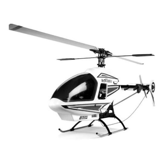
Summary of Contents for JR Ergo CCPM
- Page 1 .32–.38 AND .46 3D ASSEMBLY INSTRUCTIONS ERGO SPECIFICAT I O N S Overall Length 46.5" Tail Rotor Diameter 9.17" Overall Height 16.38" Gear Ratio 9.78 : 1 : 5.18 Main Rotor Diameter 48.5" (.32–.38) Gross Weight 6.75–7.0 lbs. 50" (.46 3D)
- Page 2 Upper Main Frame Section Assembly .....10 How JR 120 CCPM Works ......36 Upper Main Frame Clutch/Tail Pinion Installation .
- Page 3 Model Aviation, as well as a liability insurance plan to cover against possible accident or injury. All AMA charter aircraft clubs require This kit has been both engineered and manufactured by JR with help from some of individuals to hold a current AMA sporting license prior to operation of their Japan’s top R/C helicopter engineers now employed by JR.
- Page 4 Self-Aligning One-Piece Steel Clutch System Offers easy installation and adjustment with exceptional reliability. ADDITIONAL ITEMS REQUIRED TO COMPLETE THE JR ERGO 1. RADIO SYSTEM REQUIREMENTS (NOT INCLUDED): 6-channel or greater R/C helicopter system with 120° CCPM function (see list below), 5 servos, 1000 mAh receiver battery and gyro.
- Page 5 (MDS .38 Heli Engine Shown) (MDS .48 Heli Engine Shown) (JRP960079 Ergo .46 Muffler Shown) 3. BUILDING SUPPLIES (NOT INCLUDED): The following items are needed to complete the assembly of the JR Ergo: Silicone Fuel Tubing Fuel Filter Whip Antenna...
- Page 6 4. TOOLS NEEDED TO ASSEMBLE THE JR ERGO (NOT INCLUDED): Nut Drivers: 5mm, 7mm Needle Nose Pliers Scissors Phillips Screwdriver Drill and Drill Bits Small Hammer X-Acto Knife Metric Ruler Blade Balancer Ball Link Sizing Tool Ball Link Pliers Allen Wrenches: 1.5, 2.0, 2.5, 3.0mm...
- Page 7 H A R D WARE IDENTIFICAT I O N There are many various sizes and shapes of hardware included in this kit. All of the hardware, screws, nuts, etc., contained in the Ergo kit are described in the Prior to assembly, please be careful to identify each screw by matching it to the full following A, B, C manner: size screw outlines included in each step.
- Page 8 CLUTCH BELL/STA RT SHAFT ASSEMBLY ..1 pc Complete Assembly Starter Hex Adaptor 3x4mm Set Screw Use Blue & Red Threadlock * When installing the Start Shaft Bearing Block Assembly, be sure the Bearing Block is positioned so the small inside diameter bearing faces upward toward the starter hex adaptor, with the large inside 3x4mm Set Screw...
- Page 9 ROTOR HEAD ASSEMBLY 960436 980012 980017 960062 980036 980049 970006 960069 970013 960068 960064 960070 970004 980013 960066 980018 970002 970006 980044 970030 980039 981004 960067 960063 980028 960071 970001 980023 980044 970029 980040 980030 981004 970002 980040 960065 980004 970004 960060 970095...
- Page 10 ROTOR HEAD ASSEMBLY PA RTS LIST PA RT # DESCRIPTION Q U A N T I T Y COMMENTS /ADDITIONAL CONTENTS J R P 9 6 0 4 3 6 Linkage Set J R P 9 8 0 0 1 2 Socket Head Bolts, 3x6mm J R P 9 6 0 0 6 2 Head Button...
- Page 11 S TA RT SHAFT/CLUTCH/ENGINE ASSEMBLY 980012 960007 980036 960005 981025 980013 960003 981006 980004 960018 960157 980036 980036 980036 980094 981005 980013 970009 980012 980011 960004 980036 981006 960018 980036 960011 970007 960019 980036 980013 940094 970004 960006 980047 970083 960040 970001 980037...
- Page 12 S TA RT SHAFT/CLUTCH/ENGINE ASSEMBLY PA RTS LIST PART # DESCRIPTION QUANTITY COMMENTS /ADDITIONAL CONTENTS JRP960005 Starter Hex Adapter 1 - 4x4mm Set Screw JRP981025 Bearing, Sealed, 5x19x6mm JRP980013 Socket Head Bolts, 3x8mm JRP980036 Plate Washers, 3mm JRP980004 Set Screws, 4x4mm JRP960157 Start Shaft Bearing Block JRP981005...
- Page 13 WASHOUT UNIT/CCPM CONTROL SYSTEM PA RT S 960013 970012 970095 970095 980049 960012 980036 980027 970002 980035 970011 980016 970104 960425 981015 970010 980027 980035 970004 980026 980045 970184 960031 970002 970004 980120 960009 980037 980121 970002 970002 960434 970016 980037 960022 980049...
- Page 14 WASHOUT UNIT/CCPM CONTROL SYSTEM PA RT S PART # DESCRIPTION QUANTITY COMMENTS /ADDITIONAL CONTENTS JRP970095 Double Link, Long JRP970012 Washout Arm Bushing JRP960013 Washout Base JRP960012 Washout Assembly Complete w/ All Components JRP970002 Steel Joint Ball w/2x10mm Screw 10 - 2x10mm Flat Head Screws JRP970010 Washout Link 2 - Washout Link Pins JRP980049 Nylon Washer .5...
- Page 15 UPPER MAIN FRAME/BODY SET/MAIN GEAR ASSEMBLY 980025 982002 981013 960002 982001 980012 980004 970008 982016 960072 960009 981005 980013 970008 960001 980039 980013 970005 980013 980019 970024 980019 970192 960017 970024 970020 970024 980013 980019 970020 960450 980019...
- Page 16 UPPER MAIN FRAME/BODY SET/MAIN GEAR ASSEMBLY PART # DESCRIPTION QUANTITY COMMENTS /ADDITIONAL CONTENTS JRP980025 Self Tapping Screws, 2.3x8mm JRP982002 Ergo .32/.46 Canopy 5 - 2.3x8mm Self Tapping Screws JRP982015 JRP960072 Rubber Grommets JRP982001 Body Set Complete w/Canopy & Hardware JRP981005 Bearing, 1910ZZ JRP980004 Set Screws, 4x4mm...
- Page 17 LOWER MAIN FRAME/LANDING GEAR/FUEL TANK ASSEMBLY 960030 960026 960027 960030 970022 960010 970021 960027 960028 970022 960038 960037 960032 960040 960036 960033 960038 960034 970023...
- Page 18 LOWER MAIN FRAME/LANDING GEAR/FUEL TANK PA RTS LIST PART # DESCRIPTION QUANTITY COMMENTS /ADDITIONAL CONTENTS 960010 Cooling Fan Shroud 4 - 2.6x8mm Self Tapping Screws 960026 Gyro Mounting Plate 4 - 3x10mm Socket Head Bolts 960027 Lower Frame Angles 960028 Front Radio Bed 960030 Lower Main Frame...
- Page 19 TAIL ROTOR ASSEMBLY 960051 980067 960052 980006 960050 960056 980016 960058 960222 980039 970028 980037 981003 980014 960057 980039 981004 960049 970027 980078 980029 960055 980009 981004 970001 980034 980008 960054 960529 980038 Instruction Manual 960218 Ergo 30/46 CCPM 960451 980029 Decal Sheet Ergo 30 CCPM...
- Page 20 TAIL ROTOR ASSEMBLY PA RTS LIST PART # DESCRIPTION QUANTITY COMMENTS /ADDITIONAL CONTENTS JRP960218 Tail Fin Set 1 - Horizontal Fin 1 - Vertical Fin 3 - 3x12mm Self Tapping Screws 2 - 3x12mm Socket Head Bolts 2 - 3mm Lock Nuts JRP960049 Tail Drive Belt JRP960050 Tail Slide Ring Assmebly Complete w/ All Components...
- Page 21 TAIL BOOM/TAIL BRACE/TAIL BOOM CARRIER ASSEMBLY 980039 980016 970004 980024 980014 960293 960047 980024 980022 983042 960218 980039 980015 980013 983001 980009 960044 980014 960041 960046 960043 960042 980013 980010...
- Page 22 TAIL BOOM/TAIL BRACE/TAIL BOOM CARRIER PA RTS LIST PART # DESCRIPTION QUANTITY COMMENTS /ADDITIONAL CONTENTS JRP960041 Tail Brace Set 1 - Tail Brace Tube 1 - Tail Brace Connector 1 - Tail Brace T End 1 - 2.6x12mm Socket Head Bolt 1 - 2.6x15mm Socket Head Bolt JRP960042 Tail Brace Tube JRP960043 Tail Brace T End...
- Page 24 ©1999 Horizon Hobby Distributors, Inc Distributed Exclusively by Horizon Hobby Distributors www.horizonhobby.com...
- Page 25 FINAL SERVO ADJUSTMENT AND RADIO SET- U P Now that the radio system is completely installed into the helicopter, it is Pitch Range Settings n e c e s s a ry to check and adjust the following: Flight Application Low Pitch Hovering Pitch High Pitch 1.
- Page 26 It will now be necessary to establish the maximum pitch value B. Throttle Curve Settings re q u i red for your application prior to adjustment. For example, if you are Below are several examples of possible throttle curves during various a beginning pilot, then your maximum negative pitch will be -5, and your flight conditions.
- Page 27 – – [ATS REVO-MIX] PAGE ENTER DIR-RIGHT Press SEL to select AUX3 or AUTO GAIN Function -POS- HOV ZERO (JR NEJ120 only) XP8103 with NEJ450, NEJ900 & Set gain controller values as shown. – – – STOR STOR NEJ3000 Gyros...
- Page 28 FINAL PRE-FLIGHT CHECK Once all assemblies have been completed, please review the following and that each servo horn is secured with a servo horn mounting scre w. suggestions before attempting initial flights. • Verify that the gyro is operational and compensating in the correct •...
- Page 29 GENERAL MAINTENANCE Engine Check Ball Link Wear After each day of flying, fully drain the fuel tank. Then, start the Check to insure that all universal links fit freely but securely to the engine and let it idle until the engine and the fuel line are completely control balls.
- Page 30 XP652 HELI DATA SHEET ERGO 30/46 CCPM INITIAL SET- U P Modulation S-PCM • Z-PCM • PPM (FM) Model Number ___________________ Ergo 30/46 CCPM Initial Set-Up Model Name ________________________ CHANNEL THR (1) AIL (2) ELE (3) RUD (4) GER (5) PITCH (6) NORM NORM...
- Page 31 XP652 HELI DATA SHEET ERGO 46 3D CCPM 3D SET- U P Modulation S-PCM • Z-PCM • PPM (FM) Model Number ___________________ Ergo 46 3D CCPM 3D Set-up Model Name ________________________ CHANNEL THR (1) AIL (2) ELE (3) RUD (4) GER (5) PITCH (6) NORM...
- Page 32 XP8103 HELI DATA SHEET ERGO 30/46 CCPM INITIAL SET- U P MODEL NO. ____________________________________ MODEL NAME __________________________________ MODULATION SPCM - ZPCM - PPM ________________ AILE ELEV RUDD INH • ACT AUTO INH • ACT (POS. 1) DUAL-RATE Adjust as needed INH •...
- Page 33 XP8103 HELI DATA SHEET ERGO CCPM 3D SET- U P MODEL NO. ____________________________________ MODEL NAME __________________________________ MODULATION SPCM - ZPCM - PPM ________________ AILE ELEV RUDD INH • ACT AUTO INH • ACT (POS. 1) DUAL-RATE Adjust as needed INH • ACT •...
- Page 34 MODEL NO. (84) _ _ _ _ _ _ _ _ _ _ _ _ _ _ _ _ _ _ _ _ _ _ _ _ _ _ _ _ _ _ _ _ _ _ _ _ _ PCM10SXII DATA SHEET ERGO 30/46 CCPM INITIAL SET- U P MODEL NAME (81) ERGO .
- Page 35 PCM10SXII DATA SHEET ERGO 30/46 INITIAL SET-UP CONTINUED 50% Power 100% • —— —— HOV.SEL T H R O • C U RV E 100% ( 1 8 ) • 100% T H , T R I M = S L O W H O V.
- Page 36 MODEL NO. (84) _ _ _ _ _ _ _ _ _ _ _ _ _ _ _ _ _ _ _ _ _ _ _ _ _ _ _ _ _ _ _ _ _ _ _ _ _ PCM10SXII HELI DATA SHEET ERGO ERGO 46 3D CCPM 3D SET- U P MODEL NAME (81) _ _ _ _ _ _ _ _ _ _ _ _ _ _ _ _ _ _ _ _ _ _ _ _ _ _ _ _ _ _ _ _ _ _ _...
- Page 37 PCM10SXII HELI DATA SHEET ERGO 46 3D CCPM 3D SET-UP CONTINUED 100% • —— —— HOV.SEL T H R O • C U RV E 100% 100% ( 1 8 ) • T H , T R I M = S L O W H O V.
- Page 38 10X HELI DATA SHEET MODEL NO. (84) _ _ _ _ _ _ _ _ _ _ _ _ _ _ _ _ _ _ _ _ _ _ _ _ _ _ _ _ _ _ _ _ _ _ _ _ _ ERGO 30/46 CCPM INITIAL SET- U P MODEL NAME (81) _ _ _ _ _ _ _ _ _ _ _ _ _ _ _ _ _ _ _ _ _ _ _ _ _ _ _ _ _ _ _ _ _ _ _ M O D U L ATION (85) SPCM-ZPCM-PPM _ _ _ _ _ _ _ _ _ _ _ _ _ _ _ _ _ _ _...
- Page 39 10X HELI DATA SHEET ERGO 30/46 CCPM INITIAL SET-UP CONTINUED • —— —— HOV.SEL T H R O • C U RV E ( 1 8 ) • T H , T R I M = S L O W H O V.
- Page 40 10X HELI DATA SHEET MODEL NO. (84) _ _ _ _ _ _ _ _ _ _ _ _ _ _ _ _ _ _ _ _ _ _ _ _ _ _ _ _ _ _ _ _ _ _ _ _ _ ERGO 46 3D CCPM 3D SET- U P MODEL NAME (81) _ _ _ _ _ _ _ _ _ _ _ _ _ _ _ _ _ _ _ _ _ _ _ _ _ _ _ _ _ _ _ _ _ _ _ M O D U L ATION (85) SPCM-ZPCM-PPM _ _ _ _ _ _ _ _ _ _ _ _ _ _ _ _ _ _ _...
- Page 41 10X HELI DATA SHEET ERGO 46 3D CCPM 3D SET-UP CONTINUED • —— —— HOV.SEL T H R O • C U RV E 100% ( 1 8 ) • T H , T R I M = S L O W H O V.
- Page 42 U N D E R S TANDING SWA S H P L ATE CONTROL SYSTEMS Currently, there are several different types of control systems available on the market. Although the mechanical methods for transferring control to the swashplate vary, the different control systems can be broken down into two categories: 1 Servo (conventional) and CCPM (Cyclic/ Collective Pitch Mixing).
- Page 43 When you factor in the reduced parts count and easy programming, CCPM is actually easier to set up and operate than many conventional systems. For JR radio owners, please refer to the radio information contained at the front of this manual or on the following page to determine if your radio system has the CCPM function.
- Page 44 HOW JR 120 CCPM WORKS As mentioned previously, JR 120° three Servo CCPM relies on the radio’s special CCPM Swashplate Mixing, rather than a conventional mechanical mixer that is utilized to achieve the same results. The radio’s 120° 3-Servo CCPM function automatically mixes the three servos to provide the correct mixing inputs for Aileron (roll), Elevator (pitch) and Collective.
- Page 45 1. JR 10 SERIES SYSTEMS The following activation and set-up procedure should be used for all JR PCM10, 10S, 10SX, 10SxII, and 10X systems. Prior to activating the CCPM function, it is first suggested that a Data Reset Function be performed to reset the desired model number to be used back to the factory default settings.
- Page 46 Note: The travel values shown for the rudder function are for use with Piezo type gyros, like the JR NEJ-900, NEJ-400, NEJ-450, and NEJ-3000 type gyros. If a conventional mechanical type gyro is used (JR 120, 130, etc), then the travel values of the rudder...
- Page 47 Note: The travel values shown for the rudder function are for use with Piezo gyros, like the JR NEJ-900, NEJ-400, NEJ-450, or NEJ-3000 type gyros. If a conventional mechanical type gyro is used (JR 120, 130, etc.), then the travel values of the rudder will need to be...
- Page 48 Elevator Servo: We will refer to this servo as the “Front” servo. The channel number for this servo when using a JR radio is CH3. AUX 1 (Pitch) Servo: We will refer to this servo as the “ Right” servo. The channel number for this servo when using a JR radio is CH6.
- Page 49 BODY ASSEMBLY/CANOPY AT TA C H M E N T Rubber Grommets (4 pcs) Body Note: It will be necessary to trim away the unwanted plastic *Canopy (trim prior to attachment) off the canopy and side 2.3x8mm Self window areas using a Tapping Screw hobby knife.
-
Page 51: Main Rotor Blade Balancing
MAIN ROTOR BLADE BALANCING Main Rotor Blades Step 1 Step 2 Drinking Glass (2 pcs) Final Static Balancing Spanwise C.G. Balancing To static balance the main rotor blades, either attach each blade to a Place each rotor blade on a sharp edge of a table as “seesaw”... - Page 52 2x10mm Flat Head Screw test fitted to the servo to insure that the arms will attach to the servo as indicated. Since the JR ..3 pcs...
- Page 53 Please refer to your particular radio’s section as listed below, or consult your radio instru c t i o n manual for more inform a t i o n . JR PCM10, 10S, 10SX, 10SXII, 10X SYSTEMS 1) Enter the Sub-Trim Function (Code 15) 2) Adjust the Left (aileron), Right (AU X 1) and Front (elevator) servos as needed until the servo arm is exactly parallel to the servo as shown when the collective stick is in the center position.
-
Page 54: Ccpm Linkage Connections
Please also note the direction of the ball links as shown by the JR Propo name imprinted on each ball link. The JR Propo name is imprinted on the front of each ball link. When attaching the control ro d s , it is important to make sure that the JR Propo name faces outward as the links are attached to the control balls. - Page 55 CHECKING THE SWA S H P L ATE FOR LEVEL After the three control linkages have been attached to the swashplate, it will be necessary to check the swashplate to insure that it is level. To do this, turn on the radio system and place the collective stick in the center position as before. Next, check to make sure that all trim levers and knobs are also in their center position.
- Page 56 This condition is generally more common when standard type servos are used. If JR Digital Servos are used, the adjustment required is generally very small, if any. These variations in travel can be corrected by altering the travel value of each servo slightly through the Travel Adjustment Function.
- Page 57 P I T C H - T O - E L E VATOR MIXING ADJUSTMENT WITH TRAVEL ADJUST As mentioned in the previous step, the total travel of each servo can vary slightly, which can also cause the swashplate to be tilted fore and aft when the collective is moved to the extreme high and low pitch positions.
-
Page 58: Tail Control Rod Servo Connection
TAIL CONTROL ROD SERVO CONNECTION ..1 pc Note: Make certain that the Tail Rotor Servo is in the 2x8mm Flat Head Screw neutral or hover position before securing the Servo Horn to the Servo...1 pc Steel Joint Ball ..1 pc 2mm Hex Nut Servo Reversing Directions Servo Reversing Directions... - Page 59 Servo Horn. S E RVO HORN SELECTION/LINKAGE ADJUSTMENTS JR System/O.S. .32SX-H Engine JR System/Webra .35 Engine or MDS .38 Heli Engine 2.3x75mm 58mm 60mm Futaba System/Webra .35 Engine or MDS 38 Heli Engine Futaba System/O.S.
- Page 60 S E RVO INSTA L L AT I O N Servo Mounting Plates “B” ..20 pcs *Front Servo 2.6x12mm Self Tapping Screw Left Servo ..20 pcs 2.6mm Flat Washer ..8 pcs Servo Mounting Plates “B” RADIO INSTA L L ATION SUGGESTIONS Be sure to install four rubber servo grommets and eyelets to each servo prior to installation.
-
Page 61: Tail Control Rod Assembly
TAIL CONTROL ROD ASSEMBLY Thread Link 8mm on to Control Rod Tail Control Rod Bushings (5 pcs) Universal Link (2 pcs) Tail Guide Bushing ..5 pcs Tail Control Rod Bushing ..2 pcs Universal Link Tail Control Rod Thread link 8mm onto control rod TAIL CONTROL ROD INSTA L L AT I O N Square Splined Tail Guide... - Page 62 GYRO/RECEIVER/SWITCH HARNESS/BAT T E RY INSTA L L AT I O N Servo Wire Holder Caution: Be certain when installing the Gyro to the Gyro Mounting Plate that it does not come into contact with the frame of the helicopter and that the surfaces are free from oil, residue, etc.
-
Page 63: Tail Gear Case Assembly
TAIL OUTPUT SHAFT/PULLEY ASSEMBLY Pre-Assembled in kit Complete Assembly ..1 pc Spring Pin Hammer Tail Output Shaft Spring Pin Short Distance Note correct direction of Tail Edge of Work Bench Output Shaft during assembly. Long Distance Tail Case Pulley TAIL GEAR CASE ASSEMBLY 3x12mm Self Tapping Screw 3x12mm Self... -
Page 64: Tail Center Hub Assembly
TAIL CENTER HUB ASSEMBLY Tail Rotor Center Hub Be sure to engage the two 3mm Set Screws into the hole in the Tail Output Shaft 3mm Lock Nut (2 pcs) Tail Slide Ring Assembly 3mm Set Screw Use Red Threadlock Use Red Threadlock ..2 pcs 3x3mm Set Screw... - Page 65 TAIL PITCH CONTROL LEVER INSTA L L AT I O N ..1 pc 2x8 Flat Head Screw ..1 pc 2x20mm Socket Head Bolt ..1 pc 2mm Flat Washer ..1 pc Steel Joint Ball ..1 pc Tail Lever Bushing Snap Tail Pitch Control Onto Ball Lever...
- Page 66 TAIL BOOM CARRIER INSTA L L AT I O N 3mm Lock Nut Tail Boom Carrier (L&R) 3mm Lock Nut ..4 pcs 3x15mm Socket Head Bolt ..2 pcs 3x40mm Socket Head Bolt ..6 pcs 3mm Lock Nut * Do not fully tighten at this time. These bolts will be secured in Step 5-10.
-
Page 67: Tail Boom Brace Assembly
TAIL BOOM BRACE ASSEMBLY Tail Brace Connector ..1 pc 2.6x12mm Socket Head Bolt 2.6x15mm Socket Head Bolt ..1 pc 2.6x15mm Socket Head Bolt * For added boom brace strength, bond the tail brace ends to the tube after assembly with thick CA 2.6x12mm Socket Head Bolt adhesive. -
Page 68: Rotor Head Hub Assembly
ROTOR HEAD HUB ASSEMBLY Use Threadlock 3x6mm Socket Head Bolt Use Blue Threadlock Head Button ..1 pc 3x6mm Socket Head Bolt ..2 pcs Use Threadlock 3x8mm Socket Head Bolt 3x8mm Socket Head Bolt (2 pcs) Note: If you’re building the Ergo 46 3D CCPM version, please refer to the separate assembly instructions contained in the high cyclic Main Rotor Hub... - Page 69 MAIN BLADE HOLDER/SEESAW AT TA C H M E N T Note: If you are building the Ergo 46 3D CCPM version, please ..2 pcs install the Ball Bearing Seesaw Shaft Assembly, which is Seesaw Shaft bushing included with your kit..2 pcs 3x5mm Button Head Bolt Blade Spindle Shaft...
- Page 70 S WA S H P L AT E / WASHOUT ASSEMBLY INSTA L L AT I O N Washout Assembly 120° CCPM Swashplate Assembly Option: For smooth operation, pre-size the ball links with the JR ball link sizing tool prior to attachment. Complete Assembly Washout unit to swashplate connection. Connect the two washout links to the two...
- Page 71 ROTOR HEAD INSTA L L AT I O N ..1 pc 3x18mm Socket Head Bolt Rotor Head Assembly ..1 pc 3mm Lock Nut 3mm Lock Nut 3x18mm Socket Head Bolt Note: Be sure to engage the rotor hub pin into the washout base groove before securing the rotor head in place *Note: If you’re building the Ergo 46 CCPM version,...
- Page 72 F LYBAR INSTA L L AT I O N Flybar Control Arm (2 pcs) Use Blue Threadlock 4x4mm Set Screw Seesaw Shaft ..2 pcs *Flybar Bushings (2 pcs) (2 pcs) 4x4mm Set Screw ..2 pcs Use Threadlock Flybar Bushings ..2 pcs Flybar Control Arm * Be sure to insert Flybar Bushings into the Seesaw Shaft before inserting Flybar.
- Page 73 ROTOR HEAD/SWA S H P L ATE CONTROL ROD INSTA L L AT I O N Option: For smooth operation, pre- size the ball links with the JR ball link sizing tool prior to attachment *Note: For the Ergo 46 CCPM,...
- Page 74 MAIN DRIVE GEAR/AUTOROTATION ASSEMBLY 3x6mm Socket Head Bolt (4 pcs) [Tighten equally to prevent warping of Main Drive Gear] Use Threadlock Use Blue Threadlock Main Drive Gear ..4 pcs 3x6mm Socket Head Bolt Autorotation Assembly MAIN DRIVE GEAR/AUTOROTATION ASSEMBLY INSTA L L AT I O N Main Shaft Collar 4x4mm Set Screws (4) .
- Page 75 LANDING GEAR ASSEMBLY INSTA L L AT I O N 3x12mm Socket Head Bolt (4 pcs) ..4 pcs 4x4mm Set Screw ..4 pcs 3x12mm Socket Head Bolt ..4 pcs 3mm Flat Washer 3mm Flat Washer (4 pcs) ..4 pcs Landing Gear Dampers (4 pcs) 3mm Lock Nut 3mm Lock Nut (4 pcs)
- Page 76 3-4.1 .46 COOLING FAN INSTA L L AT I O N Nut Supplied with Engine Use Threadlock Note: If you’re building the Ergo .32–.36 Version, proceed to Step 3-5. Note: It will not be necessary to use the four 3x5mm Socket Head Bolts included in this screw bag.
- Page 77 3-5.1 .46 ENGINE MOUNT AT TA C H M E N T .46 Engine Mount .46 Fan Assembly Use Blue Threadlock ..4 pcs 3mm Serrated 3x15mm Socket Head Bolt Washer (4 pcs) ..4 pcs 3mm Flat Washer *See Note ..4 pcs 3mm Serrated Washer Motor Mount Direction: Motor Mount Direction:...
- Page 78 Engine and Clutch Bell are parallel. I N S TA L L ATION OF THE MUFFLER Note: The installation shown is for a .32–.36 size engine with a JR muffler (JRP960078). Installation of other .32–.36/.46 engine muffler combinations may vary. Please refer to your engine/muffler ..1 pc...
-
Page 79: Upper Main Frame Section Assembly
UPPER MAIN FRAME SECTION ASSEMBLY Upper Main Shaft Bearing Block ..18 pcs 2 pcs Position so the side Bearing Flush Body Mounting Standoff, 37mm 3x8mm Socket Head Bolt with Flange of the bearing block that has the bearing . - Page 80 UPPER MAIN FRAME CLUTCH/TAIL PINION INSTA L L AT I O N ....11 pcs 3x8mm Socket Head Bolt ....1 pc 3x8mm Socket Head Bolt 3x8mm Flat Washer 3x10mm Socket Head Bolt...
-
Page 81: Lower Main Frame Assembly
LOWER MAIN FRAME ASSEMBLY Lower Main Frame 2.6x8mm Self Tapping Screw (4 pcs) ..4 pcs 3x8mm Socket Head Bolt ..4 pcs 3x8mm Socket Head Bolt 3mm Lock Nut ..4 pcs 3mm Lock Nut (4 pcs) 2.6x8mm Self Tapping Screw Lower Frame Angle (2 pcs) 2.6x8mm Self Tapping Screw Servo Mounting Plate... - Page 82 FRONT RADIO BED/GYRO MOUNTING PLATE INSTA L L AT I O N Gyro Mounting Plate ..6 pcs Use Blue Threadlock 3x10mm Socket Head Bolt Front Radio Bed ..2 pcs 3x18mm Set Screw ..2 pcs Body Mounting Standoff, Long Body Mounting Standoff, Long 3x10mm Socket Head Bolt (6 pcs)
- Page 83 UPPER/LOWER MAIN FRAME ASSEMBLY AT TA C H M E N T ..12 pcs Use Blue Threadlock on all screws 3x22mm Socket Head Bolt ..12 pcs 12.5mm Main Frame Spacer ..6 pcs 32mm Main Frame Standoff 32mm Main Frame Standoff (6 pcs) Use Threadlock 3x22mm Socket Head Bolt (12 pcs) 12.5mm Main Frame Spacer (12 pcs)
-
Page 84: Fuel Tank Assembly
E L E VATOR ARM ASSEMBLY Elevator Arm ....1 pc 3mm Lock Nut ..1 pc 11mm Long Ball Arm ...1 pc JR Logo Direction 3mm Flat Washer Elevator Arm Pin ....1 pc 3mm Flat Washer Swashplate A Arm 3mm Lock Nut...
Need help?
Do you have a question about the Ergo CCPM and is the answer not in the manual?
Questions and answers