
Subscribe to Our Youtube Channel
Related Manuals for JR Robinson R22


Summary of Contents for JR Robinson R22
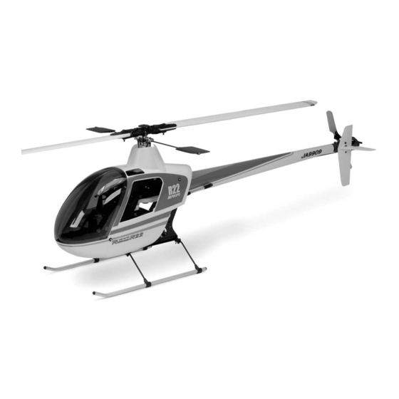
- Page 1 .46–.50 ASSEMBLY INSTRUCTIONS ERGO SPECIFICATIONS Overall Length 46.25" Tail Rotor Diameter 9.17" Overall Height 16.50" Gear Ratio 9.78 : 1 : 5.18 Main Rotor Diameter 52.75" Gross Weight 7.0–7.5 lb...
-
Page 2: Table Of Contents
Tail Control Rod Installation ....30 the Robinson R22 SS CCPM......4–6 Gyro/Receiver/Switch Harness/Battery Installation . -
Page 3: Introduction
CCPM (Cyclic/Collective Pitch Mixing). CCPM is a unique control system that mounts three servos below the swashplate with short, When first opening your JR heli kit, you will notice that all of the straight linkages directly to the swashplate at 120-degree parts are packaged and numbered to coordinate with the assembly intervals. -
Page 4: Robinson R22 Ss Ccpm Features
Provides a durable, semi-scale appearance, full decal set included, no painting required ADDITIONAL ITEMS REQUIRED TO COMPLETE THE JR ROBINSON R22 SS CCPM 1. Radio System Requirements (not included): 6-Channel or greater R/C helicopter system with 120° CCPM function (see list below) - Page 5 A .46–.50 R/C helicopter engine (JRP960079 Ergo .46 muffler shown) (MDS .48 heli engine shown) 3. Building Supplies (not included): The following items are needed to complete the assembly of the JR Robinson R22: Silicone Fuel Tubing Fuel Filter Whip Antenna...
- Page 6 4. Tools Needed To Assemble the JR Ergo (not included): Nut Drivers: 5 mm, 7 mm Needle-Nose Pliers Scissors Phillips Screwdriver Metric Ruler Drill and Drill Bits Small Hammer X-Acto Knife Blade Balancer Ball Link Sizing Tool Ball Link Pliers Allen Wrenches: 1.5, 2.0, 2.5,...
-
Page 7: Hardware Identification
All of the hardware, screws, nuts, etc., contained included in this kit. Prior to assembly, please be careful to identify in the Robinson R22 SS kit are described in the following each screw by matching it to the full size screw outlines included A, B, C manner: in each step. -
Page 8: Clutch Bell/Start Shaft Assembly
CLUTCH BELL/START SHAFT ASSEMBLY ..1 pc Complete Assembly Starter Hex Adaptor 3 x 4 mm Set Screw Use blue & red Threadlock Apply a very light coat of red Threadlock * When installing the before inserting pinion gear into the start shaft bearing start shaft bearing block. -
Page 9: Elevator Arm Assembly
ELEVATOR ARM ASSEMBLY Elevator Arm ...... 1 pc 3 mm Lock Nut ..1 pc 11 mm Long Ball Arm JR Logo Direction 3 mm Flat Washer ....1 pc Elevator Arm Pin ......1 pc Swashplate A Arm 3 mm Lock Nut... -
Page 10: Upper Main Frame Section Assembly
UPPER MAIN FRAME SECTION ASSEMBLY Upper Main Shaft-Bearing Block ........16 pcs Use blue Threadlock on all screws Bearing Flush Position so side of the 3 x 8 mm Socket Head Bolt with Flange bearing block that has *Note: Install elevator arm the bearing flush with ............ -
Page 11: Upper Main Frame Clutch/Tail Pinion Installation
UPPER MAIN FRAME CLUTCH/TAIL PINION INSTALLATION ........... 10 pcs 3 x 8 mm Socket Head Bolt ............. 10 pcs 3 mm Flat Washer 3 x 8 mm Socket Head Bolt 3 x 8 mm Flat Washer 3 x 8 mm Socket Head Bolt 3 x 8 mm Flat Washer Note: Both the clutch bell/start shaft assembly (Step 1-1) and the tail... -
Page 12: Lower Main Frame Assembly
LOWER MAIN FRAME ASSEMBLY 3 x 6 mm Socket Head Bolt ..1 pc Tail Guide Mount 3 x 6 mm Socket Head Bolt ..4 pcs 3 x 8 mm Socket Head Bolt 3 x 8 mm Socket 3 mm Head Bolt .... -
Page 13: Front Radio Bed/Gyro Mounting Plate Installation
FRONT RADIO BED/GYRO MOUNTING PLATE INSTALLATION Gyro Mounting Plate Body Mounting Standoff, 50 mm (2) 3 x 18 mm Set Screw Front Radio Bed 10 mm Use blue Threadlock Body MountingStandoff, 50 mm (2) ......6 pcs 3 x 10 mm Socket 3 x 10 mm Socket Head Bolt Head Bolt (6) .... -
Page 14: Upper/Lower Main Frame Assembly Attachment
UPPER/LOWER MAIN FRAME ASSEMBLY ATTACHMENT ....16 pcs Use blue Threadlock 3 x 22 mm Socket Head Bolt on all screws ......... 14 pcs 12.5 mm Main Frame Spacer ........2 pcs 12.5 mm Guide Spacer ..6 pcs 32 mm Main Frame Standoff ............. -
Page 15: Main Drive Gear/Autorotation Assembly
MAIN DRIVE GEAR/AUTOROTATION ASSEMBLY 3 x 6 mm Socket Head Bolt (4 pcs) [Tighten equally to prevent warping of main drive gear.] ..4 pcs Use Threadlock 3 x 6 mm Socket Head Bolt Main Drive Gear Use blue Threadlock Autorotation Hub Internal View Autorotation Assembly... -
Page 16: Landing Gear Assembly Installation
LANDING GEAR ASSEMBLY INSTALLATION Assemble and attach the landing gear assembly as shown..... 8 pcs 3 x 3 mm Set Screw ....4 pcs 3 x 12 mm Socket Head 3 x 8 mm Set Screw Bolt (4) ... 4 pcs 3 x 12 mm Socket Head Bolt .... -
Page 17: Engine Mount Attachment
ENGINE MOUNT ATTACHMENT .46 Engine Mount .46 Fan Assembly Use blue Threadlock ..... 4 pcs 3 x 15 mm Socket Head Bolt 3 mm Serrated Washer (4) ......4 pcs 3 mm Flat Washer *See Note ......4 pcs 3 mm Serrated Washer Motor Mount Direction: Motor Mount Direction: Thunder Tiger... -
Page 18: Engine Installation (All)
Check that the engine and clutch bell are parallel. INSTALLATION OF THE MUFFLER Note: The installation shown is for a .46–.50 size engine with a JR Muffler (JRP960079). Installation of other engine/muffler combinations may vary. Please refer to your ....1 pc engine/muffler instructions for proper installation. -
Page 19: Rotor Head Hub Assembly
ROTOR HEAD HUB ASSEMBLY Use Threadlock Use Threadlock 3 x 6 mm Socket Head Bolt Use blue Threadlock ....1 pc 3 x 6 mm Socket Head Bolt Head Button ....2 pcs Use Threadlock 3 x 8 mm Socket Head Bolt 3 x 8 mm Socket Head Bolt (2) Main Rotor Hub Flybar Limiter... -
Page 20: Main Blade Holder/Seesaw Attachment
MAIN BLADE HOLDER/SEESAW ATTACHMENT ..2 pcs Use red Threadlock 3 x 5 mm Button Head Bolt ..2 pcs 4 mm Lock Nut Blade Spindle Shaft ....2 pcs Dampner Rubber (2) Use red Threadlock Seesaw Spacer (Steel) Blade Holder Spacer .. -
Page 21: Swashplate Adjustment
Connect the 2 washout links to Option: For smooth operation, Washout the 2 long upper swashplate balls presize the ball links with the Assembly as shown. JR ball link sizing tool prior to attachment. 120° CCPM Swashplate Assembly Washout Unit to Swashplate Connection... -
Page 22: Rotor Head Installation
ROTOR HEAD INSTALLATION ..1 pc 3 x 18 mm Socket Head Bolt Rotor Head Assembly ........1 pc 3 mm Lock Nut 3 mm Lock Nut 3 x 18 mm Socket Head Bolt Note: Be sure to engage the rotor hub pin into the washout base groove before securing the rotor head in place. -
Page 23: Flybar Paddle Attachment
3 mm Lock Nut (2) 4-10 ROTOR HEAD/SWASHPLATE CONTROL ROD INSTALLATION Option: For smooth operation, presize the ball links with the JR ball link sizing tool prior to attachment. JR Propo ..2 pcs ..2 pcs Seesaw Arm to Main Blade Holder (1 piece double link, short) 17.5 mm... -
Page 24: Tail Output Shaft/Pulley Assembly
TAIL OUTPUT SHAFT/PULLEY ASSEMBLY Complete Assembly Preassembled in kit ..1 pc Spring Pin Hammer Tail Output Shaft Spring Pin Short Distance Note correct direction of tail Edge of Work Bench output shaft during assembly. Long Distance Tail Case Pulley TAIL GEAR CASE ASSEMBLY 2.6 x 10 mm Socket Head Bolt... -
Page 25: Tail Center Hub Assembly
TAIL CENTER HUB ASSEMBLY Tail Rotor Center Hub Be sure to engage the two 3 mm set screws into the hole in the tail output shaft. 3 mm Lock Tail Slide Ring Assembly Use red Threadlock Nut (2) ......2 pcs 3 mm set screw 3 x 3 mm Set Screw Use red Threadlock... -
Page 26: Tail Pitch Control Lever Installation
TAIL PITCH CONTROL LEVER INSTALLATION ......1 pc 2 x 8 mm Flat Head Screw ..1 pc 2 x 20 mm Socket Head Bolt ......1 pc 2 mm Flat Washer ........1 pc Steel Joint Ball ....1 pc Snap onto Tail Lever Bushing... -
Page 27: Tail Boom Carrier Installation
TAIL BOOM CARRIER INSTALLATION 3 mm Lock Nut 3 mm Lock Nut Tail Boom Carrier (L&R) ........ 4 pcs 3 x 15 mm Socket Head Bolt 3 x 40 mm Socket Head Bolt ......2 pcs ............. 6 pcs 3 mm Lock Nut * Do not fully tighten at this time. -
Page 28: Tail Boom Brace Assembly
TAIL BOOM BRACE ASSEMBLY Tail Brace Connector Two Assemblies Required ....4 pcs 2.6 x 12 mm Socket Head Bolt * For added boom brace strength, bond the tail brace ends to the tube after assembly with thick CA adhesive. Use Threadlock 2.6 x 12 mm Socket Head Bolt Tail Brace Connector... -
Page 29: Servo Installation
SERVO INSTALLATION Servo Mounting Plates “B” ....20 pcs *Front Servo 2.6 x 12 mm Self Tapping Screw Left Servo ......... 20 pcs 2.6 mm Flat Washer ..... 8 pcs Servo Mounting Plates “B” RADIO INSTALLATION SUGGESTIONS Be sure to install 4 rubber servo grommets and eyelets to each servo prior to installation. -
Page 30: Tail Control Rod Assembly
TAIL CONTROL ROD ASSEMBLY Thread Link 8 mm on to Control Rod Tail Control Rod Bushings (2) 20 mm Tail Guide Tube (1) Tail Guide Bushing (1) ..2 pcs Tail Control Rod Tail Control Rod Bushing Universal Link (2) Universal Link .. -
Page 31: Gyro/Receiver/Switch Harness/Battery Installation
GYRO/RECEIVER/SWITCH HARNESS/BATTERY INSTALLATION Caution: Be certain when installing the gyro to the gyro mounting plate that it Servo Wire Holder does not come into contact with the frame of the helicopter and that the surfaces are free from oil, residue, etc. Clean if neccessary to insure proper adhesion. -
Page 32: Servo Arm Preparation And Installation
2 x 10 mm Flat Head Screw fitted to the servo to insure that the arms will attach to the servo as indicated. Since the JR servo arm spline uses an odd number of teeth, it is sometimes possible to rotate the servo arm 180° to achieve a .... -
Page 33: Ccpm Servo Centering With The Sub-Trim Function
Please refer to your particular radio’s section as listed below or consult your radio instruction manual for more information. JR PCM10, 10S, 10SX, 10SXII, 10X SYSTEMS 1) Enter the “Sub-Trim” function (code 15). 2) Adjust the left (aileron), right (Aux 1) and front (elevator) servos as needed until the servo arm is exactly parallel to the servo as shown when the collective stick is in the center position. -
Page 34: Ccpm Linkage Connections
Please also note the direction of the ball links as shown by the “JR Propo” name imprinted on each ball link. The “JR Propo” name is imprinted on the front of each ball link. -
Page 35: Checking The Swashplate For Level
CHECKING THE SWASHPLATE FOR LEVEL After the 3 control linkages have been attached to the swashplate, it will be necessary to check the swashplate to insure that it is level. To do this, turn on the radio system and place the collective stick in the center position as before. Next, check that all trim levers and knobs are also in their center position. -
Page 36: Pitch-To-Aileron Mixing Adjustment With Travel Adjust
This condition is generally more common when standard type servos are used. If JR Digital servos are used, the adjustment required is generally very small, if any. These variations in travel can be corrected by altering the travel value of each servo slightly through the travel adjustment function. -
Page 37: Pitch-To-Elevator Mixing Adjustment With Travel Adjust
PITCH-TO-ELEVATOR MIXING ADJUSTMENT WITH TRAVEL ADJUST The total travel of each servo can vary slightly, which can also cause the swashplate to be tilted fore and aft when the collective is moved to the extreme high and low pitch positions. This situation can also be corrected if necessary through the use of the travel adjustment function. -
Page 38: Tail Control Rod Servo Connection
TAIL CONTROL ROD SERVO CONNECTION Note: Make certain that the tail rotor servo is in ....1 pc the neutral or hover position before 2 x 8 mm Flat Head Screw securing the servo horn to the servo.......1 pc Steel Joint Ball ...... -
Page 39: Throttle Linkage Installation (All)
Note: Make sure that the throttle trim is in the low position before attaching the servo horn. SERVO HORN SELECTION/LINKAGE ADJUSTMENTS JR System/Webra .35 Engine or MDS .38 Heli Engine JR System/O.S. .32SX-H Engine 2.3 x 75 mm 2.3 x 75 mm... -
Page 40: Body Preparation And Trimming
BODY PREPARATION AND TRIMMING ... 5 pcs 2.3 x 8 mm Self Tapping Screw Trim the body parts as shown using a high-speed Moto tool and/or hobby knife. Remove Remove Remove 15 mm 10 mm Remove Remove Remove /4" Note: Do not drill holes until rear body is fitted to model, as the position of the holes can vary. -
Page 41: Body Attachment/Final Fitting
BODY ATTACHMENT/FINAL FITTING Note: It will be neccessary to remove the tail case Remove tail assembly to install the rear body section. case assembly. Do not loosen the tail boom or change belt tension as this must remain set prior to rear body attachment. -
Page 43: Main Rotor Blade Balancing
MAIN ROTOR BLADE BALANCING Main Rotor Blades Step 1 Step 2 Drinking Glass (2) Spanwise C.G. Balancing Final Static Balancing Place each rotor blade on a sharp edge of a table as shown To static balance the main rotor blades, either attach each blade to a and adjust so each rotor blade “teeters”... -
Page 44: Understanding Swashplate Control Systems
(conventional) and CCPM (Cyclic/ Collective Pitch Mixing). increased precision and reduced complexity. The following is an explanation of the two most popular types of The JR CCPM System utilizes three servos for the three main swashplate control. controls: aileron (roll), elevator(pitch) and collective. The CCPM 1. -
Page 45: Radio System Requirements (Not Included)
HOW JR 120 CCPM WORKS The JR 120° three Servo CCPM relies on the radio’s special CCPM two rear control ball position as measured from the center of the swashplate mixing rather than a conventional mechanical mixer swashplate. As mentioned, this mixing of the three servos is also that is utilized to achieve the same results. -
Page 46: Ccpm Software Activation And Initial Adjustment
MODEL 1 SPCM Note: The travel values shown for the Rudder function are for use with Piezo type gyros, like the JR NEJ-900, NEJ-400, NEJ-450, or NEJ-3000 type gyros. If a B) Access the Swash Type function (code 65). Next, press conventional mechanical type gyro is used (JR 120, 130 the SEL key until “3 SERVOS”... - Page 47 Note: The travel values shown for the rudder function are to exit the Swashplate Type function and the system mode. for use with Piezo type gyros, like the JR NEJ-900, NEJ-400, NEJ-450, and NEJ-3000 type gyros. If a C) Turn the power switch on, then press the Up and Down conventional mechanical type gyro is used (JR 120, keys simultaneously to enter the function mode.
-
Page 48: Ccpm Software Activation And Initial Adjustment
-100 Note: The travel values shown for the rudder function are for use with Piezo gyros, like the JR NEJ-900, NEJ-400, NEJ-450, or NEJ-3000 type gyros. If a conventional mechanical type gyro is used (JR 120, 130, etc.), then the... -
Page 49: Important Ccpm Programming Dos And Don'ts
Aileron Servo: We will refer to this servo as the “Left” servo. movements. The channel number for this servo when using a JR radio is CH2. Minor travel value adjustments are necessary due to slight Elevator Servo: We will refer to this servo as the “Front”... -
Page 50: Final Servo Adjustment And Radio Setup
FINAL SERVO ADJUSTMENT AND RADIO SETUP Now that the radio system is completely installed into the and set the collective pitch stick to the center position as in helicopter, it is necessary to check and adjust the following: previous steps. If all linkages are properly adjusted, the swashplate/rotor head system should appear as shown in the 1. - Page 51 FINAL SERVO ADJUSTMENT AND RADIO SETUP, continued It will now be necessary to establish the maximum pitch value Once this procedure has been completed, the positive and required for your application prior to adjustment. For negative pitch settings for each flight mode can be adjusted example, if you are a beginning pilot, then your maximum through the radio’s Pitch Curve function.
-
Page 52: Final Servo Adjustment And Radio Setup
– Make certain that the compensation direction is set to “Right.” Press SEL to select AUX3 or AUTO Gain function. (JR NEJ120 only) PCM 10 Series radio with XP8103 with NEJ450, NEJ900 & Set gain controller values as shown. NEJ120 & NEJ130 Gyros... -
Page 53: Final Preflight Check
FINAL PREFLIGHT CHECK 1. Preflight Check 2. Blade Tracking Adjustment Once all assemblies have been completed, please review the Blade tracking is an adjustment to the main rotor blade pitch that following suggestions before attempting initial flights. must be accomplished during the initial test flights. •... -
Page 54: General Maintenance
GENERAL MAINTENANCE 1. Engine 4. Check Ball Link Wear After each day of flying, fully drain the fuel tank. Then, start the Check to insure that all universal links fit freely but securely to the engine and let it idle until the engine and the fuel line are control balls. -
Page 55: Xp652
XP652 HELI DATA SHEET ROBINSON R22 SS CCPM INITIAL SETUP Modulation S-PCM • Z-PCM • PPM (FM) Model Number _______________________ Model Name Robinson R22 CCPM CHANNEL THR (1) AIL (2) ELE (3) RUD (4) GER (5) PITCH (6) NORM NORM... -
Page 56: Xp8103
XP8103 HELI DATA SHEET ROBINSON R22 SS CCPM INITIAL SETUP MODEL NO. ____________________________________ MODEL NAME Robinson R22 CCPM MODULATION SPCM - ZPCM - PPM ________________ AILE ELEV RUDD INH • ACT AUTO INH • ACT (POS. 1) DUAL-RATE Adjust as needed INH •... -
Page 57: Pcm10Xii
PCM10SXII DATA SHEET ROBINSON R22 SS CCPM INITIAL SETUP MODEL NO. (84) _____________________________________ MODEL NAME (81) Robinson R22 CCPM MODULATION (85) SPCM-ZPCM-PPM ___________________ THRO AILE ELEV RUDD GEAR PITCH AUX2 AUX3 AUX4 AUX5 REVERSE SW (11) TRAVEL ADJUST Refer to the CCPM section of this manual for proper settings... - Page 58 PCM10SXII DATA SHEET ROBINSON R22 SS CCPM INITIAL SETUP, continued 50% Power 100% • —— —— HOV.SEL THRO • CURVE 100% (18) • 100% TH,TRIM=SLOW HOV.T=CENTER • • -2° Pitch 5° Pitch 10° Pitch • —— —— HOV.SEL • PITCH -5°...
-
Page 59: 59-60
10X HELI DATA SHEET ROBINSON R22 SS CCPM INITIAL SETUP MODEL NO. (84) _____________________________________ MODEL NAME (81) Robinson R22 CCPM MODULATION (85) SPCM-ZPCM-PPM ___________________ THRO AILE ELEV RUDD GEAR PITCH AUX2 AUX3 AUX4 AUX5 REVERSE SW TRAVEL ADJUST Refer to the CCPM section of this manual for proper settings... - Page 60 10X HELI DATA SHEET ROBINSON R22 SS CCPM INITIAL SETUP, continued • —— —— HOV.SEL THRO • CURVE 100% (18) • TH,TRIM=SLOW HOV.T=CENTER • • -2°Pitch 5°Pitch 10°Pitch • —— —— HOV.SEL • PITCH -10°Pitch 0°Pitch 10°Pitch CURVE • (68) •...
-
Page 61: Rotor Head Assembly
ROTOR HEAD ASSEMBLY 960436 980012 980017 960062 980036 980049 960069 970006 970013 960068 960064 960070 970004 980013 960066 980044 980018 970006 970002 960067 970110 970111 970193 980039 981004 960063 980028 970090 970001 980023 980044 980040 970029 981029 980030 981004 970002 980040 960065 980004... -
Page 62: Rotor Head Assembly
ROTOR HEAD ASSEMBLY PARTS LIST Part # Description Quantity Comments /Additional Contents JRP960059 Flybar Paddles JRP960060 Flybar JRP960061 Rotor Head Assembly JRP960062 Head Button 1 - 3 x 6 mm Socket Head Bolt JRP960063 Main Blade Holder 2 - 2 x 10 mm Flat Head Screws / 2 - Steel Joint Balls JRP960064 Main Rotor Body 2 - 3 x 8 mm Socket Head Bolts... -
Page 63: Start Shaft/Clutch/Engine Assembly
START SHAFT/CLUTCH/ENGINE ASSEMBLY 980012 960190 980036 960005 981025 980013 960003 980004 981006 960157 960018 980036 980036 980036 980094 981005 980013 970009 980012 960004 980036 981006 960018 980036 970007 980094 980036 960040 970004 980013 980056 970001 960471 980037 980036 980014 960039 950050 980021 960079 (optional) -
Page 64: Start Shaft/Clutch/Engine Assembly
START SHAFT/CLUTCH/ENGINE ASSEMBLY PARTS LIST Part # Description Quantity Comments /Additional Contents JRP960003 Clutch Assembly JRP960004 Clutch Bell Assembly Complete w/Clutch Lining JRP960005 Starter Hex Adapter 1 - 4 x 4 mm Set Screw JRP960018 Tail Drive Pinion bb Block JRP960039 Engine Mount: 46 JRP960040... -
Page 65: Washout Unit/Ccpm Control System
WASHOUT UNIT/CCPM CONTROL SYSTEM PARTS 960013 970012 970095 970095 980049 960012 980036 980027 970002 980035 970011 980016 960425 970104 981015 970010 980027 980035 970004 980026 980045 970184 960031 970002 970004 980120 960009 980037 980121 970002 970002 960434 970016 980037 960022 980049 970004 980014... -
Page 66: Washout Unit/Ccpm Control System
WASHOUT UNIT/CCPM CONTROL SYSTEM PARTS LIST Part # Description Quantity Comments /Additional Contents JRP960009 Main Rotor Shaft JRP960012 Washout Assembly Complete w/All Components JRP960013 Washout Base JRP960022 Swashplate A Arm Complete w/2-A Arms & Pins JRP960031 Servo Mounting Plate JRP960425 Swashplate Assembly Complete w/All Hardware JRP960434... -
Page 67: Upper Main Frame/Body Set/Main Gear Assembly
UPPER MAIN FRAME/BODY SET/MAIN GEAR ASSEMBLY 982147 982145 960072 982146 981013 960002 980012 980025 960072 980004 970008 981005 960009 960001 980014 960483 980039 980019 980036 970005 980013 970077 970024 960483 980039 980014 960017 970203 970192 970024 970020 980013 970024 980036 980019 980013 970020... -
Page 68: Upper Main Frame/Body Set/Main Gear Assembly
UPPER MAIN FRAME/BODY SET/MAIN GEAR ASSEMBLY PARTS LIST Part # Description Quantity Comments /Additional Contents JRP960001 Autorotation Assembly 4 - 3 x 6 mm Socket Head Screws JRP960002 Main Drive Gear 88T 4 - 3 x 6 mm Socket Head Screws JRP960009 Main Rotor Shaft JRP960017... -
Page 69: Lower Main Frame/Landing Gear/Fuel Tank Assembly
LOWER MAIN FRAME/LANDING GEAR/FUEL TANK ASSEMBLY 980012 960293 960026 980014 980039 960027 960484 980039 970021 970025 960010 980013 980026 980026 980013 960027 980002 980014 960028 980014 970106 970226 960040 960630 960629 960034 960629 960333 982149 970023 960336... -
Page 70: Lower Main Frame/Landing Gear/Fuel Tank Assembly
LOWER MAIN FRAME/LANDING GEAR/FUEL TANK ASSEMBLY PARTS LIST Part # Description Quantity Comments /Additional Contents JRP960010 Cooling Fan Shroud 4 - 2.6 x 8 mm Self Tapping Screws JRP960026 Gyro Mounting Plate 4 - 3 x 10 mm Socket Head Bolts JRP960027 Lower Frame Angles JRP960028... -
Page 71: Tail Rotor Assembly
980078 980029 960187 980089 981004 970001 980034 980008 960054 960529 960482 Instruction Manual 960628 Robinson R22 CCPM Decal Sheet 980129 Robinson R22 CCPM .50 ASSEMBLY INSTRUCTIONS 982148 ERGO SPECIFICATIONS Overall Length 46.25" Tail Rotor Diameter 9.17" Overall Height 16.5" Gear Ratio 9.78 : 1 : 5.18... -
Page 72: Tail Rotor Assembly
2 - 3 mm Set Screws JRP960217 Tail Drive Belt JRP960482 Robinson R22 SS CCPM Assembly Manual 1 JRP960528 Tail Blade Holder Set 2 - 3 x 15 mm Socket Head Bolts / 4 - 2 x 8 mm Socket Head Bolts /... -
Page 73: Tail Boom/Tail Boom Carrier Assembly
TAIL BOOM/TAIL BOOM CARRIER ASSEMBLY 980039 980016 970004 960293 980024 960047 980022 983046 980039 983034 960315 980024 970214 960519 980015 980009 960044 983012 980014... -
Page 74: Tail Boom/Tail Boom Carrier Assembly
TAIL BOOM/TAIL BOOM CARRIER ASSEMBLY PARTS LIST Part # Description Quantity Comments /Additional Contents JRP960044 Tail Brace Connector 1 - 2.6 x 12 mm Socket Head Bolt JRP960047 Tail Boom Carrier 2 - 3 x 40 mm Socket Head Bolts / 4 - 3 x 15 mm Socket Head Bolts / 6 - 3 mm Lock Nuts JRP960293 Tail Rod Guide Set... -
Page 75: Note
NOTE... - Page 76 © 2000 Horizon Hobby, Inc. Distributed exclusively by Horizon Hobby, Inc. www.horizonhobby.com...
Need help?
Do you have a question about the Robinson R22 and is the answer not in the manual?
Questions and answers