Table of Contents
Advertisement
Advertisement
Table of Contents

Related Manuals for Kenwood CK 704


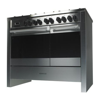
Summary of Contents for Kenwood CK 704
- Page 1 DUAL FUEL DOUBLE OVEN COOKER CK 704 Instructions for use - Installation advice...
-
Page 3: Table Of Contents
CONTENTS Page Number Introduction ..........4 Important Safeguards &... -
Page 4: Introduction
Dear Customer, Thank you for purchasing a Kenwood Dual Fuel Double Oven Cooker The safety precautions and recommendations in these instructions are for your own safety and that of others. They will also provide a means by which to make full use of the features offered by your appliance. -
Page 5: Important Safeguards & Recommendations
● IMPORTANT SAFEGUARDS WARNING When correctly installed, your product AND RECOMMENDATIONS meets all safety requirements laid down for this type of product category. After unpacking the appliance, check to However special care should be taken ensure that it is not damaged and that around the rear or the underneath of the oven door closes correctly. -
Page 6: Cooking Hob
1 - COOKING HOB Fig. 1.1 COOKING HOB 1. Triple-ring burner (TR) 3,50 kW 2. Semi-rapid burner (SR) 1,75 kW 3. Rapid burner (R) 3,00 kW 4. Auxiliary burner (A) 1,00 kW 5. Semi-rapid burner (SR) 1,75 kW 6. Auxiliary burner (A) 1,00 kW Note: ✓... -
Page 7: Control Panel
2 - CONTROL PANEL Fig. 2.1 CONTROL PANEL - Controls description 1. Front right burner control knob 2. Rear right burner control knob 3. Rear central burner control knob 4. Front central burner control knob 5. Rear left burner control knob 6. -
Page 8: How To Use The Cooking Hob
3 - USE OF COOKING HOB LIGHTING THE BURNERS GAS BURNERS To ignite the burner: Each burner is controlled by a gas tap which opens and closes the gas supply. 1) Lightly press and turn the knob anti- Line the control knob symbol up with the clockwise and position the knob sym- indicator on the control panel (fig. - Page 9 DEEP FAT FRYING BURNERS POT DIAMETER Auxiliary 12 - 14 cm For safety purposes when deep fat fry- ing, do not fill the pan more than one Semi-rapid 16 - 24 cm third full of oil. Rapid 24 - 24 cm DO NOT cover the pan with a lid and DO NOT leave the pan unattended.
-
Page 10: How To Use Fan Main Oven
4 - FAN MAIN OVEN OPERATING PRINCIPLES Attention: the oven door becomes Heating and cooking in the FAN oven very hot during operation. are obtained in the following ways: Keep children away. a. by forced convection A fan sucks in the air contained in the oven muffle, which sends it through GENERAL FEATURES the circular heating element and then... - Page 11 Fig. 4.1 Fig. 4.2 TEMPERATURE KNOB (fig. 4.1) To turn on the heating elements of the oven, set the switch knob on the desired program and select the required temperature. To set the temperature, it is necessary to make the chosen number, printed on the knob, to match with the indicator on the control panel.
- Page 12 DEFROSTING FROZEN FOODS Only the oven fan is on. To be used with the thermostat knob on “●” because the other positions have no effect. The defrosting is done by simple ventilation without heat. Recommended for: To rapidly defrost frozen foods; 1 kilogram requires about one hour. The defrosting times vary according to the quantity and type of foods to be defrosted.
- Page 13 COOKING ADVICE SIMULTANEOUS COOKING OF DIFFERENT FOODS STERILIZATION The FAN consents a simultaneous het- Sterilization of foods to be conserved, in erogeneous cooking of different foods. full and hermetically sealed jars, is done Different foods such as fish, cake and meat can be cooked together without in the following way: mixing the smells and flavours together.
-
Page 14: How To Use The Conventional Oven
5 - CONVENTIONAL OVEN OPERATING PRINCIPLES Attention: the oven door becomes Heating and cooking in the CONVEN- very hot during operation. TIONAL oven are obtained in the follow- Keep children away. ing ways: GENERAL FEATURES a. by normal convection The heat is produced by the upper The conventional oven has 3 heating and lower heating elements. - Page 15 FUNCTION SELECTOR KNOB It is recommended that you do not (fig. 5.1) grill for longer than 30 minutes at any Rotate the knob clockwise to set the one time. oven for one of the following functions. Attention: the oven door becomes very hot during operation.
-
Page 16: Cooking Guide
6 - COOKING GUIDE Temperature and times given are approximate, as they will vary depending on the quality and amount of food being cooked. Remember to use ovenproof dishes and to adjust the oven temperature during cooking if necessary. COOKING CHART Temperature Food Cooking Time (approx) -
Page 17: How To Use And Set The Electronic Programmer
7 - ELECTRONIC PROGRAMMER Description of the illuminated If you use the oven for none auto- symbols: matic or semi-automatic cooking, ensure programmer is set to man- AUTO - flashing - Programmer in auto- ual position by pushing button. matic position but not pro- grammed AUTO - always lit - Programmer in auto- The electronic programmer performs the... - Page 18 ELECTRONIC CLOCK ELECTRONIC TIMER (fig. 7.2) The programmer is equipped with an The timer program consists only of a electronic clock with an illuminated dis- buzzer which may be set for a maximum play which indicates hours and minutes. period of 23 hours and 59 minutes. Upon immediate connection of the oven If the AUTO is flashing push the but-...
- Page 19 AUTOMATIC OVEN COOKING 3. Set the temperature and the cooking program (see the relevant sections). To cook food automatically in the oven, it is necessary to: Once the oven is programmed it will 1. Set the length of the cooking time switch on automatically at the right time 2.
- Page 20 At the end of the cooking, the oven and SEMI - AUTOMATIC COOKING symbol will turn off, the AUTO This is used to switch the oven off auto- will flash and a buzzer will go off which matically after the desired cooking time can be stopped by pushing any of the has elapsed.
-
Page 21: Cleaning & Maintenance
8 - CLEANING AND MAINTENANCE ENAMELLED PARTS Important: Before cleaning or carrying out All the enamelled parts must be cleaned any maintenance disconnect the with a sponge and soapy water or other appliance from the electrical sup- non-abrasive products. ply and wait for it to cool down. Dry preferably with a soft cloth. - Page 22 GAS TAPS CORRECT REPLACEMENT OF THE BURNERS In the event of operating faults in the gas taps, call the Service Department. It is very important to check that the burner flame distributor F and the cap C has been correctly positioned (see fig. BURNERS 8.1) - failure to do so can cause serious problems.
- Page 23 TRIPLE RING BURNER The triple ring burner must be correctly positioned (see fig. 8.2 - 8.3); the burner rib must be enter in their logement as shown by the arrow. Then position the cap A and the ring B (fig. 8.3). The burners must be correctly positioned so that they cannot rotate (fig.
- Page 24 Fig. 8.6 OVEN DOOR STORAGE COMPARTMENT The storage compartment is accessible The internal glass panel can be easily through the pivoting panel (fig. 8.7). removed for cleaning by unscrewing the 2 retaining screws (Fig. 8.6). Do not use harsh abrasive clean- ers or sharp metal scrapers to Do not store flammable material in clean the oven door glass since...
- Page 25 INSIDE OF OVEN – The oven should always be cleaned after use when it has cooled down. – Remove and refit the side runner frames as described on the next chapter. – The cavity should be cleaned using a mild detergent solution and warm water.
- Page 26 REMOVING THE OVEN DOOR Fig. 8.10A The oven door can easily be removed as follows: – Open the door to the full extent (fig. 8.10A). – Attach the retaining rings to the hooks on the left and right hinges (fig. 8.10B). –...
-
Page 27: Advice For The Installer
Advice for the installer IMPORTANT – Cooker installation and maintenance must only be carried out by QUALIFIED TECHNI- CIANS and in compliance with the local safety standards. Failure to observe this rule will invalidate the warranty. – The electrical mains outlet, if located behind the cooker, must not be higher than 18 cm above the floor level. -
Page 28: Installation
9 - INSTALLATION INSTALLATION The cooker must be installed by a qualified technician and in compliance with local safety standards. This cookers has class “2/1” overheating protection so that it can be installed next to a cabinet. The furniture walls adjacent to the cooker must be made of material resistant to heat. The veneered syntetical material and the glue used must be resistant to a temperature of 90°C in order to avoid ungluing or deformations. - Page 29 LEVELLING THE COOKER The cooker is equipped with 4 LEVEL- LING FEET and may be levelled by screwing or unscrewing the feet with a spanner (fig. 9.2). It is important to observe the prescrip- tions of figures 9.3 - 9.4. Fig.
- Page 30 MOVING THE COOKER WARNING When raising the cooker to an upright position always ensure that two peo- ple carry out this manoeuvre to pre- vent damage to the adjustable feet (fig. 9.5). WARNING Be careful: do not lift the cooker by the door handle when raising to the Fig.
- Page 31 STABILITY BRACKET We recommend a stability bracket is fitted to the cooker. You can buy the type of bracket shown here from most plumbing and DIY shops. Existing slot in rear of cooker Brackets Fig. 9.8 Dotted line showing the position of cooker when fixed Outline of cooker backplate at the...
- Page 32 PROVISION FOR VENTILATION The appliance should be installed into a room or space with an air supply in accordance with BS 5440-2: 2000. For rooms with a volume of less than 5 m - permanent ventilation of 100 cm free area will be required.
-
Page 33: Gas Installation
10 - GAS SECTION IMPORTANT NOTE This appliance is supplied for use on NATURAL GAS or LPG (check the gas regulation label attached on the appliance). - Appliances supplied for use on NATURAL GAS: they are adjusted for this gas only and cannot be used on any other gas (LPG) without modification. - Page 34 INSTALLATION TO NATURAL GAS Installation to Natural Gas must conform to the Code of Practice, etc. The supply pressure for Natural Gas is 20 mbar. The installation must conform to the relevant British Standards. INSTALLATION TO LP GAS When operating on Butane gas a supply pressure of 28-30 mbar is required. When using Propane gas a supply pressure of 37 mbar is required.
- Page 35 Left gas Right gas inlet pipe inlet pipe Plug 1/2” BSP (male) Fig. 10.2 IMPORTANT PRESCRIPTIONS FOR GAS CONNECTION Rear wall Suggested area for gas mains connection Fig. 10.3...
- Page 36 CONVERSION TO NATURAL GAS OR TO LPG INJECTORS REPLACEMENT OF TOP BURNERS If the injectors are not supplied they can be obtained from the “Service Centre”. The diameter is marked on the injector in cents of millimetre. Select the injectors to be replaced according to the “Table for the choice of the injectors”...
- Page 37 TABLE FOR THE CHOICE OF THE INJECTORS Cat: 2H3+ G 30 - 28-30 mbar G 20 Nominal Reduced BURNERS G 31 - 37 mbar 20 mbar Power Power Ø injector Ø injector [kW] [kW] [1/100 mm] [1/100 mm] 1,00 0,30 72 (X) Auxiliary (A) 1,75...
- Page 38 11 - ELECTRICAL SECTION N.B. For connection to the mains, do not use adapters, reducers or IMPORTANT: The cooker must be branching devices as they can cause installed in accordance with the overheating and burning. manufacturer’s instructions. Incorrect installation, for which the If the installation requires alterations to manufacturer accepts no responsi- the domestic electrical system, call an...
- Page 39 TECHNICAL DATA ELECTRICAL FEEDER CABLE CONNECTION 230 V AC - 50 Hz To connect the supply cable: Fan Main oven - Remove the screws securing the – Grill element 2.00 kW cover “A” on the rear of the cooker – Circular element 2.50 kW (fig.
-
Page 40: Guarantee
GUARANTEE UK only If your appliance goes wrong within one year from the date you bought it, we will repair it (or replace it if necessary) free of charge provided: • you have not misused, neglected, or damaged it; • it has not been modified; •... -
Page 41: After Sales Service
AFTER SALES SERVICE If you require After Sales Service contact the MASTERCARE Domestic Appliance Helpline Telephone 08701 565550. Ser. Nr. - Page 43 Descriptions and illustrations in this booklet are given as simply indicative. The manufacturer reserves the right, considering the characteristics of the models described here, at any time and without notice, to make eventual necessary modifications for their construction or for commercial needs.
- Page 44 code 1103058 ß2...
Need help?
Do you have a question about the CK 704 and is the answer not in the manual?
Questions and answers