
Subscribe to Our Youtube Channel
Related Manuals for ORTEC 9305


Summary of Contents for ORTEC 9305
- Page 1 Model 9305 Fast Preamplifier Operating and Service Manual This manual applies to instruments marked “Rev 03" on rear panel. ® Printed in U.S.A. ORTEC Part No.605540 1202 Manual Revision B...
- Page 2 In the event ORTEC fails to manufacture or deliver items called for in this agreement or purchase order, ORTEC’s exclusive liability and buyer’s exclusive remedy shall be release...
-
Page 3: Table Of Contents
CONTENTS WARRANTY ............... ii SAFETY INSTRUCTIONS AND SYMBOLS . -
Page 4: Safety Instructions And Symbols
SAFETY INSTRUCTIONS AND SYMBOLS This manual contains up to three levels of safety instructions that must be observed in order to avoid personal injury and/or damage to equipment or other property. These are: DANGER Indicates a hazard that could result in death or serious bodily harm if the safety instruction is not observed. -
Page 5: Safety Warnings And Cleaning Instructions
SAFETY WARNINGS AND CLEANING INSTRUCTIONS DANGER Opening the cover of this instrument is likely to expose dangerous voltages. Disconnect the instrument from all voltage sources while it is being opened. WARNING Using this instrument in a manner not specified by the manufacturer may impair the protection provided by the instrument. -
Page 7: Description
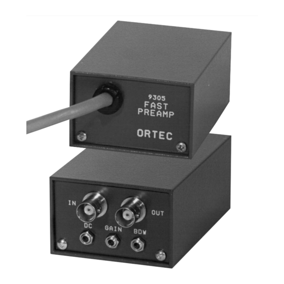
9305. (Other cable lengths are available by special order.) In addition to the fast rise time (3 ns), the 9305 has a variable voltage gain of 5-10 and can drive ±5 V Power for the 9305 is supplied through this 10-ft into a 50 load. -
Page 8: Electrical And Mechanical
. Any counter, amplifier, or timing instrument can be driven by the 9305 through 50 cable An input signal to the 9305 can be of either polarity terminated by a 50 load. If the driving instrument (e.g., it can originate from the anode or any dynode... -
Page 9: Maintenance And Calibration
. Adjust the Gain (front panel) potentiometer circuits), replacing missing hardware, and tightening of the 9305 to produce a -5 V output signal. Adjust loose hardware. Do not use excessive force when the BDW (front panel) potentiometer of the 9305 to tightening screws or nuts.
Need help?
Do you have a question about the 9305 and is the answer not in the manual?
Questions and answers