Subscribe to Our Youtube Channel
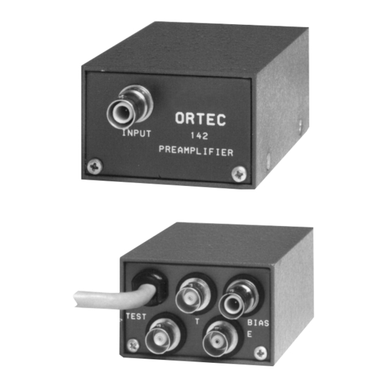
Summary of Contents for ORTEC 142IH
- Page 1 Model 142IH Preamplifier Operating and Service Manual ® Printed in U.S.A. ORTEC Part No. 717590 1202 Manual Revision C...
- Page 2 In the event ORTEC fails to manufacture or deliver items called for in this agreement or purchase order, ORTEC’s exclusive liability and buyer’s exclusive remedy shall be release...
-
Page 3: Table Of Contents
CONTENTS WARRANTY ............... ii SAFETY INSTRUCTIONS AND SYMBOLS . -
Page 4: Safety Instructions And Symbols
SAFETY INSTRUCTIONS AND SYMBOLS This manual contains up to three levels of safety instructions that must be observed in order to avoid personal injury and/or damage to equipment or other property. These are: DANGER Indicates a hazard that could result in death or serious bodily harm if the safety instruction is not observed. -
Page 5: Safety Warnings And Cleaning Instructions
SAFETY WARNINGS AND CLEANING INSTRUCTIONS DANGER Opening the cover of this instrument is likely to expose dangerous voltages. Disconnect the instrument from all voltage sources while it is being opened. WARNING Using this instrument in a manner not specified by the manufacturer may impair the protection provided by the instrument. - Page 7 51 series resistor. The Warranty of the 142IH is void if Sometimes it is necessary to simply disconnect the the protection circuit is taken out unless all of the...
-
Page 8: Description
It is intended for use in systems where the detector, rather that the preamplifier, is the major noise The 142IH will accommodate up to ±3000 V for the source in the system or in systems where the detector. The output pulse polarity is the same as ultimate in performance is not required and the cost the applied bias polarity. -
Page 9: Specifications
The performance of impedance. Type RG-62/U cable is recommended; the 142IH Preamplifier, like that of all similar this has a 93 impedance and a capacitance of instruments, is degraded as the capacity at the 13.5 pF/ft (40.1 pF/m). -
Page 10: Connection To Amplifiers
3.2. CONNECTION TO AMPLIFIERS detector (with bias applied) or the equivalent Either or both the E and T outputs of the 142IH can capacitance (without bias applied) to the Input be connected to an amplifier input for further connector on the 142IH. -
Page 11: Operation
ORTEC 114 Preamplifier Power Supply. and a series input resistor is shorted by a jumper. Figure 4.1 is a simplified block diagram of the circuits in the 142IH Preamplifier. The complete Fig. 4.1. Simplified Block Diagram of the 142IH Preamplifier. -
Page 12: Detector Bias
(about 100 M ) to the 142IH Preamplifier is used to drive two systems - Input SHV connector of the preamplifier. If the one for energy spectroscopy and the other for leakage current through the detector is appreciable, timing spectroscopy. -
Page 13: Maintenance Instructions
With only the charge terminator either E or T, should be inverted from the input and connected to the 142IH Input, the spread of the have a nominal scale factor of 45 mV per 1 MeV pulser peak thus analyzed will be due to only the equivalent energy (Si). -
Page 14: Factory Repair
If the gain of the shaping amplifier risetime of the 142IH through the T or E output is adjusted so that the output pulse height is 2.35 V connector. Connect the 419 output through the...


Need help?
Do you have a question about the 142IH and is the answer not in the manual?
Questions and answers