Subscribe to Our Youtube Channel
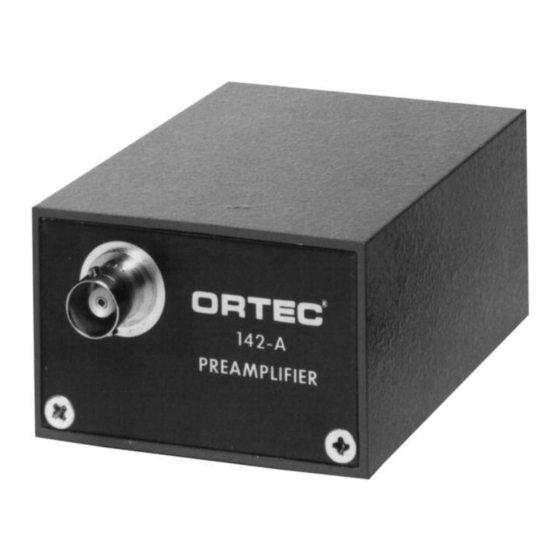
Summary of Contents for ORTEC 142A
- Page 1 Models 142A, 142B, and 142C Preamplifiers Operating and Service Manual ® Printed in U.S.A. ORTEC Part No. 627990 1202 Manual Revision D...
- Page 2 In the event ORTEC fails to manufacture or deliver items called for in this agreement or purchase order, ORTEC’s exclusive liability and buyer’s exclusive remedy shall be release...
-
Page 3: Table Of Contents
CONTENTS WARRANTY ............... . ii SAFETY INSTRUCTIONS AND SYMBOLS . -
Page 4: Safety Instructions And Symbols
SAFETY INSTRUCTIONS AND SYMBOLS This manual contains up to three levels of safety instructions that must be observed in order to avoid personal injury and/or damage to equipment or other property. These are: DANGER Indicates a hazard that could result in death or serious bodily harm if the safety instruction is not observed. -
Page 5: Safety Warnings And Cleaning Instructions
SAFETY WARNINGS AND CLEANING INSTRUCTIONS DANGER Opening the cover of this instrument is likely to expose dangerous voltages. Disconnect the instrument from all voltage sources while it is being opened. WARNING Using this instrument in a manner not specified by the manufacturer may impair the protection provided by the instrument. - Page 6 NOTICE This preamplifier has been shipped to you with its connector and before disconnecting the preamplifier protection circuit connected into the input circuit. from the detector. The protection circuit prevents destruction of the input FET due to large transients under abnormal 3.
-
Page 7: Description
142B is for detector input capacitance of 100 to 400 pF; and the 142C from a capacitance of 400 to An input protection circuit is built into the 2000 pF. The 142A and 142B can operate with preamplifier circuits to protect the input FET from higher... -
Page 8: Specifications
0 — 400 MeV Fig. 2.1. Typical Noise as a Function of 142C 0 — 400 MeV Capacitance Measured with an ORTEC RISE TIME, 0 to +0.5 V Pulse at E output on 93 572 Amplifier and 2- s Time Constant. -
Page 9: Outputs
ORTEC 114 Power Supply through the built-in captive cable. 142A +24 V, 20 mA; -24 V, 1 0 mA; +1 2 V, 15 mA; -12 V, 15 mA. 142B +24 V, 40 mA; -24 V. 10 mA; +12 V, 15 mA;... -
Page 10: Installation
24 inches for the 142A and 15 inches for the 142B and 142C. 3.4. INPUT OPERATING POWER Type RG-62/U cable is recommended for the Power for the 142 Preamplifiers is supplied through detector to preamplifier connection. -
Page 11: Detector Bias Input
142A, 142B, and 142C Preamplifiers. indicated in Fig. 4.1. This must be done very Capacitor C34 is not included in the 142A but is carefully to prevent damage to the preamplifier included in the 142B and C. Resistor R3 is furnished circuits and requires that the case be opened. -
Page 12: Energy Output
1.5 output, any overshoot present will appear to pF for the 142A and 0.5 pF for the 142B and C. increase the rise time of the timing output (Fig. 4.2). This, however, does not affect typical timing... -
Page 13: Compensation Adjustment
the slope of the leading edge is maintained over the capacitance. Although this is not necessary for whole dynamic range of the preamplifier, and since energy measurements, a typical timing experiment discriminator thresholds are typically set well below will provide the best timing resolution when the rise 1.0 V. -
Page 14: Maintenance Instructions
4. The preamplifier must be tested in conjunction with an associated main amplifier that provides the 2. Using a calibrated pulser, the 142A E output required pulse shaping. - Page 15 The noise change during use. spread can then be calculated from the formula 10. Use an ORTEC 419 Precision Pulse Generator with a matched charge termination to measure the rise time of the 142 through the T (timing) or E (energy) output.
-
Page 16: Cleaning
5.3. FACTORY REPAIR If it is necessary to clean the components and/or the This instrument can be returned to ORTEC for printed circuit in the 142 at any time, use only service and repair at a nominal cost. Our standard methanol as a cleaning solvent.


Need help?
Do you have a question about the 142A and is the answer not in the manual?
Questions and answers