
Related Manuals for ORTEC 863


Summary of Contents for ORTEC 863
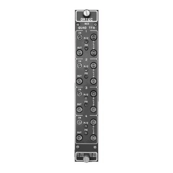
- Page 1 Model 863 Quad Timing Filter Amplifier Operating and Service Manual ® Printed in U.S.A. ORTEC Part No. 733960 0411 Manual Revision C...
-
Page 2: Warranty
In the event ORTEC fails to manufacture or deliver items called for in this agreement or purchase order, ORTEC’s exclusive liability and buyer’s exclusive remedy shall be release... -
Page 3: Table Of Contents
CONTENTS WARRANTY ................ii SAFETY INSTRUCTIONS AND SYMBOLS . -
Page 4: Safety Instructions And Symbols
SAFETY INSTRUCTIONS AND SYMBOLS This manual contains up to three levels of safety instructions that must be observed in order to avoid personal injury and/or damage to equipment or other property. These are: DANGER Indicates a hazard that could result in death or serious bodily harm if the safety instruction is not observed. -
Page 5: Safety Warnings And Cleaning Instructions
SAFETY WARNINGS AND CLEANING INSTRUCTIONS DANGER Opening the cover of this instrument is likely to expose dangerous voltages. Disconnect the instrument from all voltage sources while it is being opened. WARNING Using this instrument in a manner not specified by the manufacturer may impair the protection provided by the instrument. -
Page 7: Introduction
Excellent dc stability of the output is decay time constant. maintained by a continuous baseline restorer. Each section of the Model 863 have five sets of Several means of bandpass limiting are included to PWB jumpers to control the various functions of the achieve the pulse shaping that yields the optimum unit. -
Page 8: Specifications
10% to 90% rise time is <10 ns. The RISE TIME <10 with Integration Model 863 is shipped with this jumper in the Out Differentiation time constants set to Out, or 2 .2 position. for other Integration settings and Differentiation Out. INVERT/NONINVERT PWB jumper selectable to CROSS TALK <0.01% from any output to any... -
Page 9: Installation
Fig 4.1 for an illustration of jumper selection settings 100 ns 100k 270 pF on the PWB. To access this and other jumpers, remove the left side cover of the module. The 863 is 200 ns 470 pF shipped with the polarity set as noninverting. 500 ns... - Page 10 ±5 V into a 50 load impedance. the output driver stage is 10× noninverting. Overall dc-stability of the output level of the 863 is Fig. 4.1. Jumper Selection Settings. Bin/Module Connector Pin Assignments For Standard Nuclear Instrument Modules per DOE/ER-0457T.
Need help?
Do you have a question about the 863 and is the answer not in the manual?
Questions and answers