
Subscribe to Our Youtube Channel
Related Manuals for ORTEC 9327


Summary of Contents for ORTEC 9327
- Page 1 Model 9327 1-GHz Amplifier and Timing Discriminator Operating and Service Manual ® Printed in U.S.A. ORTEC Part No. 774750 1202 Manual Revision D...
- Page 2 In the event ORTEC fails to manufacture or deliver items called for in this agreement or purchase order, ORTEC’s exclusive liability and buyer’s exclusive remedy shall be release...
-
Page 3: Table Of Contents
CONTENTS WARRANTY ............... ii SAFETY INSTRUCTIONS AND SYMBOLS . -
Page 4: Safety Instructions And Symbols
SAFETY INSTRUCTIONS AND SYMBOLS This manual contains up to three levels of safety instructions that must be observed in order to avoid personal injury and/or damage to equipment or other property. These are: DANGER Indicates a hazard that could result in death or serious bodily harm if the safety instruction is not observed. -
Page 5: Safety Warnings And Cleaning Instructions
SAFETY WARNINGS AND CLEANING INSTRUCTIONS DANGER Opening the cover of this instrument is likely to expose dangerous voltages. Disconnect the instrument from all voltage sources while it is being opened. WARNING Using this instrument in a manner not specified by the manufacturer may impair the protection provided by the instrument. -
Page 7: Description
Spectrometry (Fig. 1.1), Time-of-Flight Mass Spectrometry (Fig. 1.2), and LIDAR applications. The amplifier provides a 1-GHz bandwidth to The Model 9327 is optimized for use with the minimize the noise and rise time contributions to millivolt signals produced by microchannel plate... - Page 8 Fig. 1.2. The Model 9327 in a Simplified Illustration of a Time-of-Flight Mass Spectrometer. The Model 9308 picosecond TIME ANALYZER functions as a multiple-stop time spectrometer. amplitudes: 0 to -30 mV and 0 to -150 mV. A fine wide. The shift in the timing output (walk) as a gain control permits varying the gain over nominally function of pulse amplitude is typically less than ±40...
-
Page 9: Specifications
The Model 9327 provides two fast-negative NIM A 3-meter long captive power cord terminated in a logic signals suitable for operating other timing 9-pin, D connector supplies power to the unit. Power instruments with picosecond time resolution. A 100- can be derived from the mating connectors on a... -
Page 10: Controls And Indicators
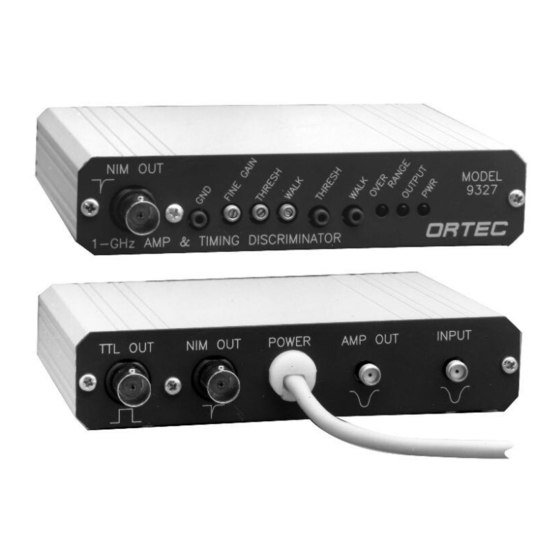
2.3. CONTROLS AND INDICATORS compatible with the preamplifier power connectors INPUT RANGE (Coarse Gain) Circuit board on ORTEC Models 9328, 9308, 4003, 4002P, or jumper near the amplifier INPUT permits input most ORTEC spectroscopy amplifiers. Power range selection for 0 to -30 mV or 0 to -150 mV. -
Page 11: Installation And Operation
3.4. OUTPUT CONNECTIONS The 9327 is packaged in a compact case, allowing There are four outputs on the Model 9327: two fast- it to be placed close to the signal source (such as negative NIM logic outputs, one TTL output, and a detector). -
Page 12: Adjusting The Input Signal
Detector operating conditions external attenuations prior to the 9327 input will also allow The walk adjustment has the greatest effect on the the input signal level to be adjusted. Any external lowest 10-20% of the input range. attenuators must have sufficient bandwidth to preserve the risetime of the signal. -
Page 13: Input Range Selection
This source is the dominant driver test point; to the left of the TTL output; and to the in the walk performance of the 9327 for most right of the INPUT. Pull the board out by pulling on usable signal levels. -
Page 14: Maintenance And Factory Repair Service
Return Authorization Number can be assigned to the unit. 5. POWER CONNECTOR PINOUT The power cable of the 9327 is compatible with the ORTEC standard preamp power outputs: 9327 Usage Standard Preamp Power FUNCTION...
Need help?
Do you have a question about the 9327 and is the answer not in the manual?
Questions and answers