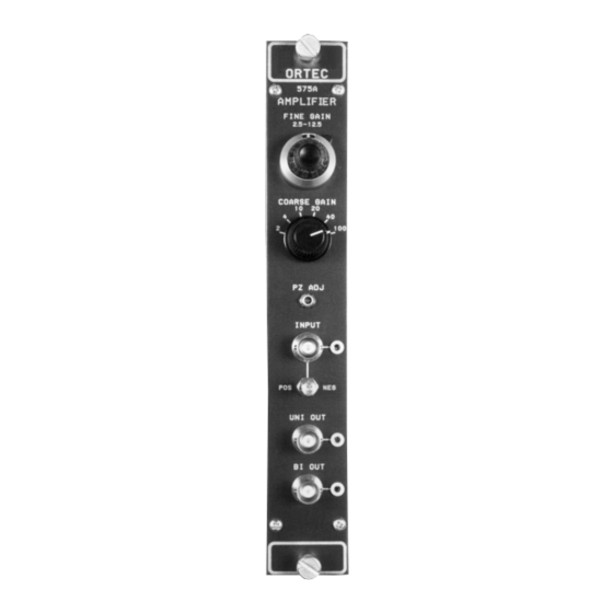
Summary of Contents for ORTEC 575A
- Page 1 Model 575A Amplifier Operating and Service Manual ® Printed in U.S.A. ORTEC Part No. 717460 1202 Manual Revision C...
- Page 2 In the event ORTEC fails to manufacture or deliver items called for in this agreement or purchase order, ORTEC’s exclusive liability and buyer’s exclusive remedy shall be release...
-
Page 3: Table Of Contents
CONTENTS WARRANTY ............... ii SAFETY INSTRUCTIONS AND SYMBOLS . -
Page 4: Safety Instructions And Symbols
SAFETY INSTRUCTIONS AND SYMBOLS This manual contains up to three levels of safety instructions that must be observed in order to avoid personal injury and/or damage to equipment or other property. These are: DANGER Indicates a hazard that could result in death or serious bodily harm if the safety instruction is not observed. -
Page 5: Safety Warnings And Cleaning Instructions
SAFETY WARNINGS AND CLEANING INSTRUCTIONS DANGER Opening the cover of this instrument is likely to expose dangerous voltages. Disconnect the instrument from all voltage sources while it is being opened. WARNING Using this instrument in a manner not specified by the manufacturer may impair the protection provided by the instrument. -
Page 7: Description
The unipolar output is used for spectroscopy in differentiated pulse amplitude systems where dc coupling can be maintained from the 575A to the analyzer. A BLR (baseline restorer) =differentiation time circuit is included in the unit for improved peramplifier pulse decay time performance at all count rates. - Page 8 Pole-zero cancellation is accomplished by the dc path across the differentiation capacitor adds an network shown in Fig. 2. The pole [s + (1/T )] due to attenuated replica of the preamplifier pulse to just the preamplifier pulse decay time is cancelled by cancel negative undershoot...
-
Page 9: Active Filter
The pole-zero adjust is accessible on the front panel of the 575A and can easily be adjusted by observing the baseline on an oscilloscope with a monoenergetic source or pulser having the same decay time as the preamplifier under overload conditions. -
Page 10: Specifications
WALK ± 5 ns at 0.5 s shaping for 50:1 dynamic 2.3. INPUT range, including contribution of an ORTEC 551 or 552 Constant-Fraction Timing Single-Channel INPUT BNC (UG-1094A/U) front and rear panel Analyzer. connectors accept either positive or negative pulses... -
Page 11: Electrical And Mechanical
The 575A incorporates pole-zero cancellation to 3.1. GENERAL enhance the overload and count rate characteristics The 575A operates on power that must be furnished of the amplifier. This technique requires matching from a NIM-standard bin and power supply such as the network to the preamplifier decay-time constant the ORTEC 4001A/4002A Series. -
Page 12: Connection Of Test Pulse Generator
The 575A has almost constant gain for all shaping DIRECTLY INTO THE 575A Since the input of the modes; therefore, the optimum shaping can be 575A has 1000-... -
Page 13: Shorting Or Overloading The Amplifier Output
10-turn locking potentiometer) select and precisely adjust the gain factor for the amplification in the 575A. Switch settings are ×2, 4, 10, 20, 40, and 100. Continuous fine gain range is from ×0.5 to ×12.5 using markings of 500 through 1250 dial divisions. -
Page 14: Standard Setup Procedure
Connect the preamplifier power cable to the Preamp connector on the 575A rear panel. Turn on power in the bin and power supply and allow the electronics of the system to warm up and stabilize. -
Page 15: Operation With Semiconductor Detectors
Test input of the preamplifier. Adjust the attenuator so that the 575A output amplitude is ~9 V. d. Observe the Unipolar output of the 575A with an oscilloscope. Adjust the PZ ADJ control for proper response according to Fig. 8. Use the clamp circuit in Fig. - Page 16 E , as determined by the bias voltage using data from several ORTEC silicon oscilloscope. surface-barrier semi-conductor radiation detectors. The full-width-half-maximum (FWHM) resolution spread due to amplifier noise is then...
- Page 17 The electronic noise-resolution spread can be measured directly with a pulse height analyzer and the mercury pulser as follows: a. Select the energy of interest with an ORTEC 419 Precision Pulse Generator. Set the amplifier and biased amplifier gain and bias level controls so that the energy is in a convenient channel of the analyzer.
-
Page 18: Operation In Spectroscopy Systems
Fig. 14. Since natural alpha radiation occurs only a. Keep interconnection capacitance between the above several MeV, an ORTEC 444 Biased detector and preamplifier to an absolute Amplifier is used to suppress the unused portion of minimum (no long cables). -
Page 19: Other Experiments
Using a Proportional Counter. low-noise amplifying system and lower gas amplification, these effects can be reduced and a Block diagrams illustrating how the 575A and other considerable improvement in resolution can be ORTEC modules can be used for experimental obtained. - Page 20 Fig. 19. Gamma-Ray Pair Spectrometry. Fig. 20. Gamma-Gamma Coincidence Experiment.
-
Page 21: Maintenance
Gain Input Polarity Shaping Time Constant a. Connect a positive pulser output to the 575A input and adjust the pulser to obtain +10V at the unipolar output. This should require an input pulse of 13.3 mV using a 100- terminator at the input. -
Page 22: Suggestions For Troubleshooting
Location Voltage 5.3. SUGGESTIONS FOR ±50 mV TROUBLESHOOTING ±60 mV In situations where the 575A is suspected of a ±0.7 V malfunction, it is essential to verify such ±1.0 V malfunction in terms of simple pulse generator ±60 mV impulses at the input. The unit must be 0 to 0.8 V... - Page 23 *16 +12 V Coaxial 1 2 V Coaxial Spare bus Coaxial Reserved bus *41 117 V ac (neutral) Spare *42 High-quality ground Spare Ground guide pin Reserved Pins marked (*) are installed and wired in ORTEC’s 4001A and 4001C Modular System Bins.


Need help?
Do you have a question about the 575A and is the answer not in the manual?
Questions and answers