
Related Manuals for ORTEC 113


Summary of Contents for ORTEC 113
- Page 1 Model 113 Scintillation Preamplifier Operating and Service Manual ® Printed in U.S.A. ORTEC Part No. 717560 1202 Manual Revision B...
- Page 2 In the event ORTEC fails to manufacture or deliver items called for in this agreement or purchase order, ORTEC’s exclusive liability and buyer’s exclusive remedy shall be release...
-
Page 3: Table Of Contents
CONTENTS WARRANTY ............... ii SAFETY INSTRUCTIONS AND SYMBOLS . -
Page 4: Safety Instructions And Symbols
SAFETY INSTRUCTIONS AND SYMBOLS This manual contains up to three levels of safety instructions that must be observed in order to avoid personal injury and/or damage to equipment or other property. These are: DANGER Indicates a hazard that could result in death or serious bodily harm if the safety instruction is not observed. -
Page 5: Safety Warnings And Cleaning Instructions
SAFETY WARNINGS AND CLEANING INSTRUCTIONS DANGER Opening the cover of this instrument is likely to expose dangerous voltages. Disconnect the instrument from all voltage sources while it is being opened. WARNING Using this instrument in a manner not specified by the manufacturer may impair the protection provided by the instrument. -
Page 7: Description
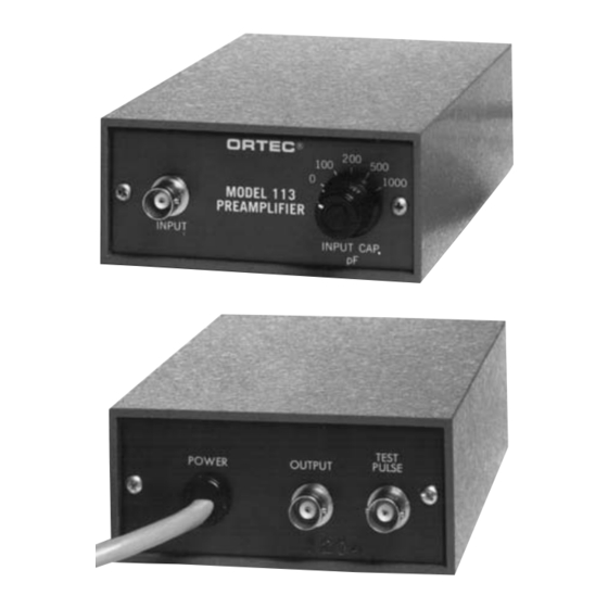
RELATED EQUIPMENT INPUT CAP pF Switch selects desired input capacity: 0, 100, 200, 500, 1000 pF. The 113 can be operated with any ORTEC Shaping Main Amplifier. Test input pulses can be furnished INPUT from any ORTEC Pulse Generator. BNC connector; isolated for 1000 V; positive or... -
Page 8: Installation Instructions
3.2. CONNECTION TO A SHAPING MAIN AMPLIFIER 3.4. TEST PULSE The 113 can be used to drive long lengths of 93 A voltage pulse can be inserted at the Test Pulse cable to a shaping amplifier and is designed to be connector on the rear of the 113. -
Page 9: Maintenance Instructions
1 X 10 . If a pole-zero-cancelled amplifier is used following the 113, it will be necessary to adjust the pole-zero trim on the amplifier each time a different input capacitance is selected for the 113.
Need help?
Do you have a question about the 113 and is the answer not in the manual?
Questions and answers