Subscribe to Our Youtube Channel
Summary of Contents for ORTEC 570
- Page 1 Model 570 Spectroscopy Amplifier Operating and Service Manual Printed in U.S.A. ORTEC Part Number 733480 1202 Manual Revision E...
- Page 2 In the event ORTEC fails to manufacture or deliver items called for in this agreement or purchase order, ORTEC’s exclusive liability and buyer’s exclusive...
-
Page 3: Table Of Contents
TABLE OF CONTENTS WARRANTY ..............i 1 DESCRIPTION . - Page 4 ILLUSTRATIONS Fig. 1.1. Differentiation in Amplifier Without Pole-Zero Cancellation ......2 Fig. 1.2. Differentiation in a Pole-Zero Canceled Amplifier ....... . 2 Fig.
-
Page 6: Description
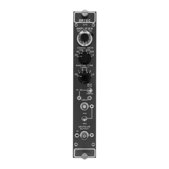
The output is unipolar and is used for spectroscopy preamplifier pulse decay time in systems where dc coupling can be maintained from the 570 to the analyzer. A BLR (baseline restorer) circuit is included in the 570 for improved For a 1-... -
Page 8: Active Filter
The pole-zero adjust is accessible on the front panel of the 570 and can easily be adjusted by observing the baseline on an oscilloscope with a monoenergetic source or pulser having the same decay time as the preamplifier under overload conditions. -
Page 9: Specifications
2 s shaping and gain 1 00. Factory preset at 50 s to match normal characteristics of ORTEC preamplifiers. TEMPERATURE INSTABILITY BLR Locking toggle switch selects a source for the Gain 0 .0075%/°C, 0 to 50°C. gated baseline restorer discriminator threshold level DC Level <±50... -
Page 10: Outputs
570 at the module position in the bin. -
Page 11: Connection Of Test Pulse Generator
TERMINATING CONSIDERATIONS a large series isolating capacitor is also required since the 570 input is dc coupled. The ORTEC test Since the 570 unipolar output is normally used for pulse generators are designed for direct connection. -
Page 12: Shorting Or Overloading The Amplifier Output
AMPLIFIER OUTPUT to 50% of that which is available in the sending in- strument. The 570 output is dc coupled with an output impedance of about 0.1 . If the output is shorted To use shunt termination at the receiving end of the... -
Page 13: Front Panel Connectors
BLR discriminator level, which can be controlled manually or automatically. The output can be used to correct for dead time in the ORTEC MCA by connecting it to the MCA Busy input. PREAMP Provides power connections from the bin and power supply to the ORTEC preamplifier. -
Page 14: Pole-Zero Adjustment
Use a CO calibration source; place it about 25 cm from the active face of the detector. The unipolar output pulse from the 570 should be about 8 to 10 V, using a preamplifier with a conversion gain of 170 mV/MeV. - Page 15 Set the 570 controls as for normal operation; this includes gain, shaping, and input polarity. c. Connect the source of 1-kHz square waves through an attenuator to the Test input of the preamplifier. Adjust the attenuator so that the 570 output amplitude is about 9 V.d.
-
Page 16: Blr Threshold Adjustment
5 s /cm horizontal deflection. Trigger the oscilloscope with the Busy output from the 570. d. Reduce the control setting until the baseline discriminator begins to trigger on noise; this corresponds to about 200 counts/s from the Busy output. -
Page 17: Operation With Semiconductor Detectors
Turn on the 419 Precision Pulse Generator and noise-resolution spread versus bias voltage, using adjust the pulser output to any convenient readable data from several ORTEC silicon surface barrier voltage, E , as determined by the oscilloscope. The semiconductor radiation detectors. - Page 18 The amplifier noise-resolution spread can be measured directly with a pulse height analyzer and the mercury pulser as follows: a. Select the energy of interest with an ORTEC 419 Precision Pulse Generator. Set the amplifier and biased amplifier gain and bias level controls so that the energy is in a convenient channel of the analyzer.
-
Page 19: Operation In Spectroscopy Systems
Fig. 4.11. Since natural alpha radiation occurs Reasonable care is required to obtain such results. only above several MeV, an ORTEC 444 Biased Amplifier is used to suppress the unused portion of Some guidelines for obtaining optimum resolution the spectrum;... -
Page 20: Other Experiments
S C I N T I L L A T I O N - C O U N T E R G A M M A SPECTROSCOPY SYSTEMS The ORTEC 570 Block diagrams illustrating how the 570 and other can be used in scintillation-counter spectroscopy ORTEC modules can be used for experimental systems as shown in Fig. -
Page 22: Maintenance
Fully CW for 300 mV 3. Hewlett-Packard 3400A rms Voltmeter. a. Connect a positive pulser output to the 570 Input and adjust the pulser to obtain +10 V at the 570 output. This should require an input pulse of 6.6 mV, using a 100 terminator at the input. - Page 23 LINEARITY The integral nonlinearity of the 570 can be measured by the technique shown in Fig. 5.1. In effect, the negative pulser output is...
-
Page 24: Suggestions For Troubleshooting
Our standard procedure for repair ensures the same In situations where the 570 is suspected of a quality control and checkout that are used for a new malfunction, it is essential to verify such instrument. - Page 25 Reset (Auxiliary +12 volts Coaxial -12 volts Coaxial Spare Bus Coaxial Reserved Bus 117 volts ac (Neut.) Spare High Quality Ground Spare Ground Guide Pin Reserved Pins marked (*) are installed and wired in ORTEC’s 4001A and 4001C Modular System Bins...


Need help?
Do you have a question about the 570 and is the answer not in the manual?
Questions and answers