
Related Manuals for Transcell Technology PC35


Summary of Contents for Transcell Technology PC35
- Page 1 North American Service Manual MODEL PC SERIES Version 2 March 25, 1997 Revision B1.1 April 4, 2000 Prepared by TRANSCELL TECHNOLOGY, INC.
-
Page 2: Table Of Contents
B.1.4.1 Recognized Host Commands ............B-3 B.1.5 NCI 3800 / Triner Demand Format ............... B-4 B.1.5.1 Recognized Host Commands ............B-4 B.1.6 Transcell Technology Demand Format............B-5 B.1.6.1 Recognized Host Commands ............B-5 B.1.7 Transcell Technology Continuous Format............. B-6 B.1.8 Detecto Demand / Continuous Format............ - Page 3 Transcell Technology “Demand” Weigh Data Record ............B-5 Transcell Technology “Demand” Status Record..............B-5 B-10 Transcell Technology “Continuous” Weigh Data / Status Record........B-6 B-11 Detecto Weigh Data / Status Record.................. B-7 B-12 Fairbanks “Demand” Weigh Data / Status Record .............. B-8...
-
Page 4: Chapter 1: Introduction
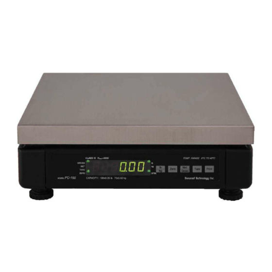
PC-70 is a 70 lb (30 kg) and the PC-150 is a 150 lb (70 kg) scale. GROSS TARE ZERO STABLE CAPACITY: 70 x 0.05 lb, 30 x 0,02 kg CLASS = 1500 Temp. Range: 0 to 40° C ZERO TARE PRINT GROSS MODEL Transcell Technology inc. PC-70 FIGURE 1-1: PC Series Front Panel... -
Page 5: Chapter 2: Legal For Trade Sealing
CHAPTER 2: LEGAL FOR TRADE SEALING OVERVIEW The scale can be prepared for commercial use by sealing access to the calibration switch, to meet the requirements for a legal-for-trade scale. 2.1.1 SEALING THE SCALE Once calibration has been successfully completed, then the scale can be sealed as follows: 1. -
Page 6: Chapter 3: General Troubleshooting Flowchart
CHAPTER 3: GENERAL TROUBLSHOOTING FLOWCHART START Try The Following In Order Of Appearance: Try The Following In Order Of Appearance: Is the 1. Check for proper AC Adapter Voltage . Does 1. Replace AC Adapter. Scale Stable 2. Check environment. Scale Turn On 2. -
Page 7: Chapter 4: Illustrated Parts List
CHAPTER 4: ILLUSTRATED PARTS LIST PC-30 AND PC-70... - Page 8 ITEM PART NO. DESCRIPTION 380190008 Stainless Steel Platform 211040020 Load Cell – FAD-20 (PC-30) 211040045 Load Cell – FAD-45 (PC-70) 380190036 Bottom Spacer - Aluminum 380190037 Top Spacer - Aluminum 380190013 Adjustable Foot – 250116237 AC Adapter – 12 VDC, 500 mA ITEM PART NO.
-
Page 9: Pc-150
PC-150... - Page 10 ITEM PART NO. DESCRIPTION 380190008 Stainless Steel Platform 380360001 Top Spacer - Aluminum 211040100 Load Cell – FAD-100 380360007 Bottom Spacer - Aluminum 380190013 Adjustable Foot – 250116237 AC Adapter – 12 VDC, 500 mA...
-
Page 11: Chapter 5: Assembly / Disassembly
CHAPTER 5: ASSEMBLY / DISASSEMBLY 5.1 PC-30 and PC-70 Tools Required: 5 mm Allen Wrench Phillips Head Screwdriver 1. Remove the scale platter (1) and set aside. 2. Using the 5 mm Allen wrench, remove the [2] load cell mounting bolts (2). 3. -
Page 12: Pc-150
5.2 PC-150 Tools Required: 5 mm Allen Wrench Phillips Head Screwdriver 1. Remove the scale platter (1) and set aside. 2. Using the 5 mm Allen wrench, remove the [2] load cell mounting bolts (2). 3. Lift off the sub-platform assembly and aluminum spacer (3), and set aside. 4. -
Page 13: Opening Up The Pc-150 Base Unit
Figure 5-2: Opening up the PC-150 Base Unit... -
Page 14: Chapter 6: Internal Wiring Diagram
CHAPTER 6: INTERNAL WIRING DIAGRAM Load Cell Main / ADC Board Assy E– S– Setup Switch Female DSUB9 – Ferrite Bead Core 1 2 3 4 5 6 7 8 9 10 1 2 3 4 SCALE RXD SCALE TXD Ferrite Bead Core TO REMOTE DISPLAY/ KEY... -
Page 15: Chapter 7: Theory Of Operation
CHAPTER 7: THEORY OF OPERATION THEORY OF OPERATION OVERVIEW Refer to Appendix C for reference designators. 7.1.1 MAIN / ADC BOARD ASSEMBLY Power to the scale is supplied by a 12 VDC, 500 mA adapter. Regulator U1 supplies +5 VDC to the digital components. Regulator U8 supplies + 10 VDC to the analog components including load cell excitation. -
Page 16: Appendix A: Technical Specifications
APPENDIX A: TECHNICAL SPECIFICATIONS ANALOG SPECIFICATIONS Full Scale Input Signal 16 mV, including dead load Internal Resolution Approximately 150,000 counts Displayed Resolution Up to 3,500 graduations max Measurement Rate 10 Meas/sec, nominal System Linearity Within 0.02% of FS Calibration Method Software Calibration, with long term storage in EEPROM Excitation Voltage +10 VDC... -
Page 17: Appendix B: Serial Data Formats Information
APPENDIX B: SERIAL DATA FORMATS INFORMATION SERIAL DATA FORMATS B.1.1 SERIAL DATA FORMATS OVERVIEW The COM1 serial port is a full duplex RS-232 port designed for connection to a serial printer, computer, or remote display. Consult the PC Series Operation Manual for information on pinouts and cable diagrams. -
Page 18: Consolidated Controls Continuous Format
“Z” - This command is sent to the scale to zero the scale. The scale will disregard this command if the scale is in motion, positive overload or negative overload. The scale will also disregard this command if it is not in gross mode or within the zero reset range. -
Page 19: Toledo 8213 Demand Format
B.1.4 TOLEDO 8213 DEMAND FORMAT Figure B-3 shows the weigh data record sent to the host when the scale receives a Print (“W”) command. The same weigh data record is sent out of the serial port if the PRINT key is pressed on the scale’s front panel. -
Page 20: Nci 3800 / Triner Demand Format
“A” - This command is sent to the scale to request an acknowledgement. This acknowledgement consists of two characters: <STX> and <CR>. B.1.5 NCI 3800 / TRINER DEMAND FORMAT Figure B-5 shows the weigh data record sent to the host when the scale receives a Print (“W”<CR>) command. -
Page 21: Transcell Technology Demand Format
= pound GR = Gross + = Positive Feed kg = kilogram NT = Net – = Negative * with leading zero suppression FIGURE B-8. Transcell Technology “Demand” Weigh Data Record <STX> <S1> <S2> <ETX> Question Mark Transmission Status Character 2:... -
Page 22: Transcell Technology Continuous Format
2 = Zero Start KG = kilograms 3 = Motion and Zero Transmission 4 = Not Ready Status Character 1: 0 = valid 1 = Under 2 = Over FIGURE B-10. Transcell Technology “Continuous” Weigh Data / Status Record Page B-6... -
Page 23: Detecto Demand / Continuous Format
B.1.8 DETECTO DEMAND / CONTINUOUS FORMAT The Detecto SDF (Serial Data Format) can work both as a Demand type and a Continuous type, depending on the commands received from the host. Upon power up, the scale defaults to Demand type. The scale disregards the type setting programmed for Mode of Serial Transmission. -
Page 24: Fairbanks 70-2453-4 Demand Format
B.1.9 FAIRBANKS 70-2453-4 DEMAND FORMAT Figure B-12 shows the weigh data / status record sent to the host when the scale receives a Print (<CR>) command. The same weigh data record is sent out of the serial port if the PRINT key is pressed on the scale’s front panel. - Page 25 “C” - This command is sent to the scale to toggle among the configured units. Even if successful, the host receives no response from the scale. The host must issue a <CR> command to determine if the command was processed by the scale.
-
Page 26: Appendix C: Circuit Diagrams
APPENDIX C: CIRCUIT DIAGRAMS Please see attached schematic diagram sheets.
Need help?
Do you have a question about the PC35 and is the answer not in the manual?
Questions and answers