Table of Contents
Advertisement
Quick Links
Download this manual
See also:
Setup Manual
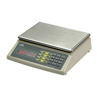
TC-100 Series
Digital Counting Scale
Operation Manual
Revision 1.3
April 24, 2002
2001-2002 Transcell Technology, Inc.
Contents subject to change without notice.
Transcell Technology, Inc.
975 Deerfield Parkway
Buffalo Grove, IL 60089
Tel (847) 419-9180
Fax (847) 419-1515
E-mail:
transcell@transcell.net
Web:
www.transcell.net
Advertisement
Table of Contents

Related Manuals for Transcell Technology TC-100 Series


Summary of Contents for Transcell Technology TC-100 Series
- Page 1 TC-100 Series Digital Counting Scale Operation Manual Revision 1.3 April 24, 2002 2001-2002 Transcell Technology, Inc. Contents subject to change without notice. Transcell Technology, Inc. 975 Deerfield Parkway Buffalo Grove, IL 60089 Tel (847) 419-9180 Fax (847) 419-1515 E-mail: transcell@transcell.net...
- Page 2 Electromagnetic Compatibility Statement for Europe PRODUCT TC-100 Series Directives with which this equipment complies Harmonized Standards applied: EMC 89/336/EEC EMC Directive EMC 92/31/EEC EMC Directive EMC 93/68/EEC EMC Directive EN 55022:1998 Class B EN 61000-3-2:1995 + A1:1998 + A2:1998 EN 61000-3-3:1995...
-
Page 3: Table Of Contents
TABLE OF CONTENTS Page Chapter 1: Introduction to the Transcell TC-100 Series Digital Counting Scale......1-1 Chapter 2: Getting Started ......................2-1 Chapter 3: Basics of Operation ....................... 3-1 Display........................... 3-1 3.1.1 Light Emitting Diode (LED) Display..............3-1 Keyboard ........................3-2 3.2.1... - Page 4 Operator Errors ....................C-1 C.1.2 Calibration Errors ..................... C-1 LIST OF FIGURES TC-100 Series Front Panel ..................... 1-1 TC-100 Back Panel ......................... 2-1 Latitude Compensation Zones (USA) ..................2-2 TC-100 Display Detail ......................3-1 Function and Numeric Keys Layout..................3-2 User Menu Key Assignments....................
-
Page 5: Chapter 1: Introduction To The Transcell Tc-100 Series Digital Counting Scale
INTRODUCTION TO THE TRANSCELL TC-100 SERIES DIGITAL COUNTING SCALE The Transcell Model TC-100 Series Digital Counting Scale is an easy to use, high-resolution counting scale featuring keyboard tare and APW entry. It is equipped with many useful features that are normally found on more expensive scale products, including memory accumulator and target values. -
Page 6: Chapter 2: Getting Started
CHAPTER 2: GETTING STARTED After unpacking the scale, a small amount of preparation is required before the scale can be used. Please refer to Figure 2-1 below as needed. POWER COM1 SERIAL ON/OFF PORT (RS-232) CONNECTOR SWITCH Figure 2-1: TC-100 Back Panel Step 1. -
Page 7: Latitude Compensation Zones (Usa)
Seattle Boston Minneapolis Detroit San Francisco Chicago Philadelphia Washington Denve St. Louis Los Angeles Memphis Atlanta Dallas Houston Miami Figure 2-2 : Latitude Compensation Zones (USA) Page 2-2... -
Page 8: Chapter 3: Basics Of Operation
NET number of pieces. APW WT Indicates the Average Piece Weight of the pieces on the platform. TARGET Indicates that a value for check weighing has been entered. TABLE 3-1: TC-100 Series Annunciator Definitions Page 3-1... -
Page 9: Keyboard
3 .2 KEYBOARD The keyboard is composed of ten function keys and ten numeric keys. Refer to Figure 3-2 for the overall layout and key locations. SAMPLE/SAVE APW WT/MODE TARGET CLEAR TARE ZERO PRINT TC-100 MODEL FIGURE 3-2: Function and Numeric Keys Layout 3.2.1 FUNCTION AND NUMERIC KEYS Z ero - This key sets the scale to display zero. -
Page 10: General Scale Operation
3.3 GENERAL SCALE OPERATION 3.3.1 WEIGHING AN ITEM 1. Ensure that the WT annunciator is lit. If it is not lit, press the Clear key. 2. If necessary, press the Zero key to obtain a weight reading of zero. 3. Place the object to be weighed on the scale’s platter and allow the weight indication to stabilize. -
Page 11: Clearing The Piece Count
If the items you will be counting require a container, you must first tare the container off by pressing the TARE key. The scale switches to TARE mode and sets the displayed weight to zero. Press the SAMPLE / SAVE key. Press the SAMPLE key. The scale displays “10” and is prompting you to place ten identical items on the platform. -
Page 12: Chapter 4: Advanced Features And Operation
CHAPTER 4: ADVANCED FEATURES AND OPERATION AVERAGE PIECE WEIGHT (APW) ENTRY If you already know the Average Piece Weight or APW of the items you wish to count, then use the following procedure. 4.1.1 AVERAGE PIECE WEIGHT (APW) ENTRY 1 . Using the numeric and decimal point keys, key-in the actual unit weight value. 2. -
Page 13: Using The Target Value
USING THE TARGET VALUE This function works in conjunction with the piece counting feature and allows your scale to act as a checkweigher. This is useful if you are filling a container with a pre-determined amount of items. To use, you must enter a target value. For example, if you wish to fill a bottle with 100 items you would set your target value to 100. -
Page 14: Chapter 5: Configuration
CHAPTER 5: CONFIGURATION CONFIGURATION OVERVIEW The scale contains two main setup menus: The Setup (“F”) menu configures the factory settings for your scale. The User (“A”) menu configures the COM1 serial communication port and enables some user options. The Setup and User menus consist of several menu selections, each with its own sub- menu of choices. -
Page 15: Exiting The User Menu
Baud Rate Data Bits, Parity Transmission Mode Display Check Press "6" 8n 7O 7E key to begin 1200 2400 4800 9600 # of LF Entry ID No. Entry Serial Port Mode ID No. Enable Press "6" Press "6" key to begin key to begin Figure 5-2: User Menu Chart 5.3.3 EXITING THE USER MENU... -
Page 16: User Menu Procedures
NAME/CODE DESCRIPTION CODE/VALUE Selects the baud rate for data transmission through the serial port. 1200 2400 Baud Rate 4800 9600√ Selects the number of data bits and parity of serial transmission. 8n√ "8n" = 8 data bits with no parity bit Data Bits and "7O"... -
Page 17: Lf (Line Feeds) Number Entry (A9)
5.4.2 LF (Line Feeds) Number Entry (A9) While in the User Menu mode, scroll to "A 9", then scroll down once using the 6 key to enter the Line Feeds menu. The display will momentarily show "ET LF", followed by the current line feeds value. Use the front panel numeric keys to key-in the actual line feeds value. -
Page 18: Chapter 6: Calibration
It is a good idea to check the calibration of your scale from time to time with a precision test weight. Transcell recommends that you perform a new calibration on your digital scale at least once a year. -
Page 19: Minimum / Recommended Calibration Test Weights
MODEL Capacity / Graduation Minimum Test Weight Recommended Test Weight TC-100-2 2 lb x 0.0002 lb 0.02 lb 2 lb TC-100-5 5 lb x 0.0005 lb 0.05 lb 4 lb to 5 lb TC-100-10 10 lb x 0.001 lb 0.1 lb 7 lb to 10 lb TC-100-20 20 lb x 0.002 lb... -
Page 20: Appendix A: Specifications
APPENDIX A: SPECIFICATIONS CONSTRUCTION: OPERATING TEMPERATURE RANGE: Housings: Tan ABS 32°F to 104°F Sub-Platform & Base: Metal (0°C to 40°C) Platter: Tan ABS w/ Stainless Top POWER SOURCE: Feet: Non-skid Hard Rubber AC Adapter, 9 VDC, 500 mA , DISPLAY: included 6 Character, 7-Segment Red LED COM1 SERIAL PORT:... -
Page 21: Appendix B: Serial Port Information
Figure B-3 shows a suggested cable diagram for a PC-type computer. The cable shown in Figure B-3 is a standard Transcell cable – Model NMC-1. 1. Plug the serial device cable (not included) directly into the DSUB9 serial port connector. -
Page 22: Default Print Format
B.1.2 DEFAULT PRINT FORMAT Figure B-4 shows the fixed format of the print format. NOTE: The TARE and NET fields are blank when a tare has not yet been established in the system. The PCS field is blank when an APW has not yet been established in the system. -
Page 23: Continuous Mode
B.1.3.2 CONTINUOUS MODE The Demand mode is used to interface to computers, scoreboards and other remote devices requiring constant data updating. The transmission occurs at the end of each display update. Figure B-6 shows the serial data format for the Continuous Mode. <STX>... -
Page 24: A Ppendix C: Error Messages
APPENDIX C: ERROR MESSAGES ERROR MESSAGES If the scale encounters an error condition, it will display a message alerting the operator. A description of each display follows: C.1.1 OPERATOR ERRORS Message Explanation A weight greater than the rated capacity has been applied to the scale. Remove the weight from the platter. - Page 25 (3 hrs/150 miles maximum per occurrence). After sixty (60) days, the warranty covers the cost of replacement parts only. However, at the discretion and prior approval of TRANSCELL, certain equipment may be returned , freight pre-paid, for repair, free of any parts or labor charges.
Need help?
Do you have a question about the TC-100 Series and is the answer not in the manual?
Questions and answers