
Related Manuals for Transcell Technology TI-500E SS


Summary of Contents for Transcell Technology TI-500E SS
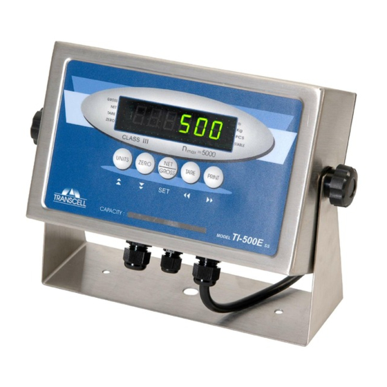
- Page 1 TI-500E SS Digital Weight Indicator Setup / Operation Manual Revision 1.1 July 9, 2012...
-
Page 2: Table Of Contents
TABLE OF CONTENTS Page INTRODUCTION ..............................1 FCC NOTE ................................1 INSTALLATION ..............................2 PREPARATION ..............................2 CONNECTIONS ..............................2 CONNECTING THE WEIGH PLATFORM ....................... 3 CONNECTING THE SERIAL I/O DEVICE ....................4 CONNECTING THE POWER SUPPLY ......................4 CONFIGURATION .............................. 4 OVERVIEW .............................. -
Page 3: Introduction
©Transcell Technology, Inc. 2009-2012. All rights reserved. The information contained herein is the property of Transcell Technology and is supplied without liability for errors or omissions. No part may be reproduced or used except as authorized by contract or other written permission. The copyright and the foregoing restriction on reproduction and use extend to all media in which the information may be embodied. -
Page 4: Installation
Electrical Power The TI-500E SS indicator has been designed to operate from 100 to 240 VAC at 50/60 Hz. All units ship with the appropriate power plug for its area of intended use. -
Page 5: Connecting The Weigh Platform
CONNECTING THE WEIGH PLATFORM ATTENTION INSTALLERS: It is highly recommended that you install the enclosed green/yellow cable between the load cell cable shield and the AC ground lug on the main PCBA. Do not connect the load cell cable shield to the green load cell input terminal. The TI-500E-SS indicator contains a connection terminal on the main board assembly for connection to the load cell cable. -
Page 6: Connecting The Serial I/O Device
CONNECTING THE SERIAL I/O DEVICE The TI-500E SS model comes standard with one full duplex RS-232 serial port, designed for connection to a computer or a serial printer. The same port may be also used as a simplex, RS-232 port designed for connection to a remote display. -
Page 7: Accessing The Menus
ACCESSING THE MENUS To access the Setup (“F) menu: 1. Power off the indicator. 2. Locate the slide switch on the rear cover and move it to the opposite position. NOTE: A metal plate held on by two drilled-head screws may conceal the slide switch. 3. -
Page 8: Setup Menu Descriptions
SETUP MENU DESCRIPTIONS This section provides more detailed descriptions of the selections found in the Setup Menu Chart. Factory-set defaults are shown in bold; (NA) for North America and ( ) for Europe. € NOTE: Some selections are subject to local legal metrology regulations CODE/NAME DESCRIPTION SELECTION LIST... - Page 9 CODE/NAME DESCRIPTION SELECTION LIST Allows the lb/kg key to be disabled so that an operator cannot 0 (€) accidentally press the key and change the displayed units. Units 1 (NA) Conversion "0" = Disable the Units key "1" = Enable the Units key Places indicator into the zero calibration routine.
-
Page 10: Setup Menu Procedures
CODE/NAME DESCRIPTION SELECTION LIST Selects the minimum weight at which the auto print function will Key-in work if enabled. Selections are in display divisions (d). Scrolling 0 - 100 Auto Print Min. Weight down with the ZERO key one level begins the procedure. 1 (NA/€) “0”... -
Page 11: User Menu Descriptions
USER MENU DESCRIPTIONS This section provides more detailed descriptions of the selections found in the User Menu Chart. Factory-set defaults are shown in bold; (NA) for North America and ( ) for Europe. € CODE/NAME DESCRIPTION SELECTION LIST Selects the baud rate for data transmission through the serial port. 300, 600, 1200, 2400, 4800, Baud Rate... -
Page 12: User Menu Procedures
USER MENU PROCEDURES This section provides instructions for all of the User Menu procedures. ID Number Entry (A8) 1. While in the User Menu mode, scroll to "A 8", and then scroll down once using the ZERO key to enter the ID Number menu. 2. -
Page 13: Calibration
CALIBRATION CALIBRATION OVERVIEW If your indicator was shipped as a complete scale, then calibration is not necessary. Please check with your installer or supplier if you are unsure. Transcell recommends having your weighing equipment checked by a qualified scale technician at least once a year depending on its intended use and working environment. -
Page 14: View Calibration Values (F18)
6. At this time it is suggested that the calibration values be recorded for future use (see next section). If the calibration was not successful, one of the error messages below will appear. Take the indicated action to correct the problem, and then perform a new calibration. "Err0"... -
Page 15: Key-In Zero Calibration Value (F19)
KEY-IN ZERO CALIBRATION VALUE (F19) Note: This procedure is intended for emergency use only in the case of non-volatile memory loss. A valid zero calibration value, obtained from a successful F16 calibration procedure, must be used. 1. While in the Setup mode, scroll to "F 19", and then scroll down once using the ZERO key. The display will momentarily show "ET C 0", followed by a value of zero 2. -
Page 16: Operation
Indicates that a tare weight has been established in the system. TARE Indicates the unit of the displayed weight. PCS stands for “pieces”. lb, kg, PCS STABLE This light is on whenever the scale is stable. TABLE 4: TI-500E SS Annunciator Definitions... -
Page 17: Keyboard
KEYBOARD The keyboard is composed of five function keys shown below. ZERO TARE PRINT UNITS GROSS FUNCTION KEYS Units – This key toggles the indicator among the available weight units if enabled in the User (“A”) menu. Available weight units include lb, kg and pieces. Zero - This key sets the indicator to display zero provided the following conditions are met: 1. -
Page 18: Piece Counting Mode
PIECE COUNTING MODE IMPORTANT NOTE: The piece counting function cannot be used in commercial (NTEP) applications. To activate this mode, set F30 to 3. This mode is used to indicate the number of pieces of an item you have placed on the scale’s platform and is accessed by pressing the UNITS key. To ensure accuracy, the parts you are counting must be consistent in weight. -
Page 19: Remote Display Mode
REMOTE DISPLAY MODE To activate this mode, set F30 to 2. This mode is used to emulate a remote display for a separate indicator. For it to work properly, a remote indicator must be transmitting information to the TI-500E SS continuously and at the same transmission (baud) rate configured in A1. LEGAL FOR TRADE SEALING Indicators can be sealed for commercial (Legal for Trade) applications as follows. -
Page 20: Appendix A: Specifications
0.56" (14 mm) 7-segment, LED, 6 Digit Additional Symbols Net, Gross, Stable, Tare, lb, kg, Zero, PCS Keyboard 5-key flat membrane panel POWER TI-500E SS 100-240 VAC, 50/60 Hz, 30W DC Power Consumption 80mA + 30mA/350Ω Load Cell ENVIRONMENTAL –10° to +40 ° C Operating Temperature -25°... -
Page 21: Appendix B: Serial Port Information
APPENDIX B: SERIAL PORT INFORMATION SERIAL PORT MODES DEMAND DUPLEX MODE The Demand Duplex Mode provides a two way serial transmission mode. In this mode, the output information is transmitted on demand; either by pressing the PRINT key on the indicator’s front panel or upon receiving a recognized command from a host device (i.e. -
Page 22: Output Strings
OUTPUT STRINGS TEXT PRINT TICKET The Text Print Ticket (A6=0) is designed specifically for a serial printer. The Text Print Ticket with MP- (A6=3) is reserved for operators who are using a Transcell MP-20 printer with 20 Auto Label Feed labels and desire to have the labels feed automatically after each printout. -
Page 23: Appendix C: Displayed Error Codes
APPENDIX C: DISPLAYED ERROR CODES CODE MODE MEANING / POSSIBLE SOLUTION Normal Operating Gross Overload. A weight greater than the rated capacity has been Mode applied to the scale. Remove the weight from the platter or try re- calibrating the scale. Otherwise, check for a bad load cell connection or possible load cell damage due to overloading.
Need help?
Do you have a question about the TI-500E SS and is the answer not in the manual?
Questions and answers