Table of Contents
Advertisement
Quick Links
N6.2400 GL-RZ3/LFL
N6.2900 GL-RZ3/LFL
N7.3600 GL-RZ3/LFL
N7.4500 GL-RZ3/LFL
Operating instructions
For specialist installation engineers
Dual fuel burners
de ......................................... 4200 1035 0500
fr ........................................... 4200 1040 8000
it ........................................... 4200 1041 4900
nl .......................................... 4200 1041 5000
............................................. 4200 1035 0600
09/2011 - Art. Nr. 4200 1040 7900A
Advertisement
Table of Contents

Related Manuals for elco N6.2400 GL-RZ3/LFL


Summary of Contents for elco N6.2400 GL-RZ3/LFL
- Page 1 N6.2400 GL-RZ3/LFL N6.2900 GL-RZ3/LFL N7.3600 GL-RZ3/LFL N7.4500 GL-RZ3/LFL Operating instructions For specialist installation engineers Dual fuel burners de ......... 4200 1035 0500 fr ........... 4200 1040 8000 it ........... 4200 1041 4900 nl .......... 4200 1041 5000 ..........4200 1035 0600...
-
Page 2: Table Of Contents
General information Contents General information Contents ..........................2 Important notes ......................... 3 Burner description ......................4 Installation General information regarding burner assembly ............... 5 Boiler lining for GL-RZ3/LFL burner .................. 6 Burner assembly........................ 7 Burner head setting data GL-RZ3/LFL ................8 Gas train Gas train description .................... -
Page 3: Important Notes
Any other type of applica- use of suitable aids. The transport Instanzen (SVGW Gas Direc- tion requires the approval of ELCO. The instructions on the packaging must be tives G1 - Cantonal specifi- burner may only be used in accordance complied with. -
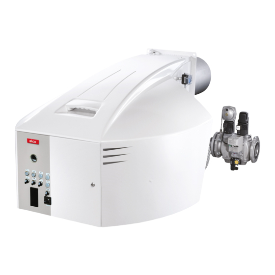
Page 4: Burner Description
General information Burner description Load regulator (option) Body Gas inlet flange Burner tube Integrated switch cabinet Burner fixing flange Air intake box Mechanical coupler Hoisting eyes Connector for inspection glass cooling Air pressure switch Fan motor Y10 Servomotor for air and gas flaps 102 Pump 09/2011 - Art. -
Page 5: Installation
Installation General information regarding burner assembly Tightening torques During installation, commissioning and maintenance, the following torques for unions must be complied with. Recommended tightening torques Standard unions N.B.: In general, the correct tightening torques have been applied when the unions are tightened hand-tight using a screwdriver (ISO 272) or angled Allen key. -
Page 6: Boiler Lining For Gl-Rz3/Lfl Burner
Installation Boiler lining for GL-RZ3/LFL burner Boiler lining The burner lining must be installed right- angled to the burner tube. Possible trimming work (bevelling, rounding) as required for reverse boilers, for example, should done at a diameter not below 70% of the combustion chamber diameter. -
Page 7: Burner Assembly
Installation Burner assembly = see dimensioned drawings = see dimensioned drawings = combustion chamber diameter = 70 to 200 mm = standard muffle depth (option : extensions: see technical data) Note for reverse flow boilers! For reverse flow boilers, the dimension T1 is only a recommended value. -
Page 8: Burner Head Setting Data Gl-Rz3/Lfl
Installation Burner head setting data GL-RZ3/LFL Ø a Ø b Ø c N6.2400 60.5 N6.2900 60,5 N7.3600 N7.4500 09/2011 - Art. Nr. 4200 1040 7900A... -
Page 9: Gas Train
Installation Gas train Gas train description The burner's scope of delivery may include a Gas trains with a double gas valve are Low- and high-pressure gas trains gas train. In this case, the burner and the gas intended for the supply, main shut-off, gas fil- If the outlet side of the regulator, i.e. -
Page 10: Basic Design
Installation Gas train Basic design Low pressure 100 Burner 314 Gas pressure switch for checking valve seals or valve 101 Gas pressure impulse pipe tightness control device 120 Air flap 349 Servomotor 141 Ball valve 142 Gas filter Options in accordance with country-specific requirements: 150 Gas control butterfly 143 Pressure gauge with pushbutton valve 151 Double gas valve with integrated regulation... -
Page 11: Description Of Gas Train With Mbc
Installation Gas train Description of gas train with MBC... Description Gas valve group Gas train with MBC The gas trains with Dungs MBC ... The gas valve group is defined on a Technical data: double gas valves MBC... are used for system-specific basis. -
Page 12: Description Of Dungs Mbc Double Gas Valve
Installation Gas train Description of Dungs MBC double gas valve... (gas multiblock) Pressure switches MBC-300/ Technical data 700... Gas multiblock MBC-.../SE: Type of gas: Gases in accordance with DVGW worksheet G 260/1, gas families 1, 2, 3 Electrical data: 230 V -15% + 10%, other voltages on request MBC-1200... -
Page 13: Changing Mbc-300-700-1200 Filter
Installation Gas train Changing MBC-300-700-1200 filter Setting the MBC-300-700-1200-SE pressure regulating component Filter inspection must be carried out at least once a year Replace filter if p between pressure port 1 and 2 > 10 mbar. Replace filter if p between pressure port 1 and 2 is twice as high as the last measurement. -
Page 14: Setting Mbc-1900-5000-Se Pressure Regulating Component
Installation Gas train Setting the MBC-1900-5000-SE pressure regulating component Adjusting the MBC-1900-5000-SE 5. Apply a security seal to the adjusting pressure regulating component screw (see below). 1. Open the protective caps. Optimum combustion and ignition safety must be ensured. 2. Start the burner, correction of set values possible while burner in operation (see figure). -
Page 15: Description Of Double Gas Valve Vgd
Installation Gas train Description of double gas valves VGD... with servomotors SKP Technical data Double gas valves VGD with servo- motors SKP: Type of gas: Gases in accordance with DVGW worksheet G 260/1, gas families 1, 2, 3 and biogas (H S-content 0.1 Vol.% max.), Electrical data: 220 V -15%...240 V +10%... -
Page 16: Gas Filters
Installation Gas train Gas filter Installation and mounting of the gas filter The gas filter may be installed in any desired position. Take care only to observe the direction of flow of the gas (arrow on filter housing). Make sure there is adequate clearance to facilitate the removal of the cover and replace- ment of the filter cartridge. -
Page 17: Gas/Air Pressure Switch
Installation Gas train Gas/air pressure switch Gas pressure switch GW...A5/A6 Gas pressure switch A5 Technical data: The gas pressure switch is designed to monitor the gas flow pressure. It can be Type of gas: used for monitoring either falling Gases according to DVGW Worksheet pressure (minimum) or rising pressure G 260/1, gas families 1, 2, 3 (maximum, specified for equipment... -
Page 18: Leakage Controller Test Burner
Gas train Leakage controller Test burner Wieland 7P socket Filter element O-ring Ø10.5x2.25 Fuse T6.3 250V Ø 5x20 Yellow indicator On : Leakage test OK Red indicator On : Leakage test NOK Manual clear Spare fuses pa (p2) pressure switch Ø 9 pe + 20mbar pe (p1) pressure switch Ø... -
Page 19: Hydraulics
Installation Hydraulics General information regarding fuel oil system Fuel oil hydraulics diagram 100 Burner 101 Fan 118 Nozzle 120 Air flap 143 Pressure gauge (optional) 175 Filter 176 Pump 178 Solenoid valve, supply line 349 Servomotor 09/2011 - Art. Nr. 4200 1040 7900A... -
Page 20: Fuel Oil Pressure Switch
Installation Hydraulics Fuel oil pressure switch Fuel oil pressure switch Setting the fuel oil pressure switch Fuel oil pressure switches are used to max. (only for burners with a return nozzle): monitor burners to ensure that they do The shut-off pressure is the ring line not exceed or fall below specific fuel oil pressure with a full load plus approx. -
Page 21: General Information Regarding Fuel Oil System
Installation Hydraulics General information regarding fuel oil system Fuel oil connection Fuel oil pressure regulator (supply Hoses are used to make a connection to line) The supply pressure is regulated by the the fuel oil tubes or the gate valves. To pressure regulator fitted in the pump prevent kinks and therefore any risk of and, depending on the burner output... - Page 22 Installation Hydraulics Pump type J7 Areas of application - Light, medium-grade oil Pumping capacity - Two-line system. Capacity (l/hr) - Generally connected to the solenoid valve in the nozzle line Description of Functions The gearbox draws the fuel oil from the tank through the built-in filter and supplies it under pressure to the valve which controls the oil pressure for the...
- Page 23 Installation Hydraulics Pump type J7 General Attachment Flange attachment as per EN 225. Model 1000 Model 1001/1002 Connections Conical Cylindrical in acc. with ISO 228/1 Supply line and backflow 1/4" NPTF G 1/2 Nozzle outlet 1/8" NPTF G 1/4 Pressure test connection 1/8"...
- Page 24 Installation Hydraulics Pump type TA3 Areas of application Pumping capacity Capacity (l/hr) - Domestic oil and heavy-grade oil (for use with kerosene, please contact SUNTEC) - Two-line system. Description of Functions The gearbox draws the fuel oil from the tank and supplies it under pressure to the valve which controls the oil pressure for the nozzle line.
- Page 25 Installation Hydraulics Pump type TA3 General Attachment Flange attachment Connections Cylindrical in acc. with ISO 228/1 Supply line and backflow G 1/2 Nozzle outlet G 1/2 Pressure test connection G 1/4 Vacuum test connection G 1/4 Shaft Ø 12 mm Bypass-plug Used in the vacuum connection for two-line installaiton...
-
Page 26: Nozzle Line 3-Stage
Installation Hydraulics Nozzle line, 3-stage The nozzles for the 3-stage nozzle line All the Monarch and Steinen nozzles are selected so as to meet the maximum have permanent labels containing the performance requirements of the boiler following information (subject to change with the best possible control range and and based on CEN standards): high combustion quality overall. - Page 27 Installation Hydraulics Nozzle line, 3-stage Oil throughput with pump pressure in bar STEINEN Oil through- Kg/hr put at 7 bar Pressure in bar 10.00 38.28 41.93 45.29 51.36 54.14 11.00 42.11 46.13 49.82 56.50 59.56 12.00 45.94 50.32 54.36 61.64 64.98 13.00 49.77...
-
Page 28: Commissioning
Commissioning Control and safety unit LFL 1.../LGK... LFL 1.../LGK... is designed for control- regional regulations. Other control and ling and monitoring burners that operate safety unit variants can be obtained on on the basis of a stepped or modulating request. ... -
Page 29: Electrical Servomotor
Commissioning Electrical servomotor Field of application The SQM5... series servomotors are designed for driving gas and air flaps in medium to high output fuel oil and gas burners. It is primarily designed for use in the regulation of gas and combustion airflow depending on the load. - Page 30 Commissioning Electrical servomotor Description The SQM servomotor has been The "SQM" servomotor is designed designed for dual-wire control by con- troller or switching units with change- for use in fuel oil, gas or two-stage over contacts. burners that operate in accordance with Suitable potentiometers can be fitted for the sliding or modulating principle.
-
Page 31: Flame Monitor Probe Current Measurement
Commissioning Flame monitor Probe current measurement Using a UV probe for flame monitor- of up to 50°C; higher ambient tempera- QRA2. tures reduce the service life considera- For the monitoring method, the UV bly. radiation from hot flame gases is used to create the flame signal. - Page 32 Commissioning Flame monitor Probe current measurement Probe currents and test equipment Min. required or max. achievable probe current in µA (DC) QRA5x.C... QRA5x.D... QRA2 Ionisation QRA5x.E… QRA5x.G… Automatic control unit LFL1… LGK16… Test Recommended Tester KF 8832 equipment M1 - microammeter Ri max. 5000 Ω; M1 - microammeter Ri max.
-
Page 33: Connecting The Gas Train, Electrical Connection, Checks Before Commissioning
Commissioning Gas train connection Electrical connection Checks before commissioning All electrical installation and connec- Gas train connection furnace. tion work must only be carried out by The connectors on the burner must be The electrical connection of the burner a suitably qualified electrician. used for connecting the gas train. -
Page 34: Gas Connection
Commissioning Gas connection Gas connection Type of gas test Leak test The gas lines and valve groups should The gas line upstream of the burner gas Prior to mounting the burner to the gas be installed and taken into operation in valve group must be installed in accord- feed line check the available type of gas accordance with the applicable engi-... -
Page 35: Fuel-Air Coupler Control
Commissioning Fuel-air coupler control Fuel-air coupler control Mechanical coupler This finely tuned coupler control system When using the 3-stage fuel oil system, allows the relevant fuel-air ratio to be set only the air flap is moved via the drive. across the entire control range. For use Depending on the drive or air flap in gas mode, fuel and air are evenly setting, the output stages can be... -
Page 36: Design Of Switch Cabinet Door
Commissioning Switch cabinet door layout -K02 load regulator -P210 Ignition transformer lamp -P144 Main oil valve lamp Supply line -P146 Fuel oil valve lamp Stage 1 -P147 Fuel oil valve lamp Stage 2 -P148 Fuel oil valve lamp Stage 3 -P244 Gas valve lamp -P246... -
Page 37: Dual Fuel Load Regulator
Commissioning Dual fuel load regulator (gas) Commissioning of the burner (item 1); check combustion! N.B.: For satisfactory regulation, the General warnings: curve characteristic must be set in The drive can be disengaged both from such a way that where possible, the entire adjustment range of the curve the camshaft and the drive shaft (see characteristic, from part load to full... - Page 38 Commissioning Dual fuel load regulator (fuel oil) O2 rate too low: gradually move the set using the limit switch [8] in the limit switch to a higher position until same way as for stages 1 and 2 the required rate is reached. The burner output must not be higher O2 rate too high: disengage the servo- than the equivalent of the maximum...
-
Page 39: Control
Commissioning Control Before commissioning the system for Lockout after safety time expires the first time, the following controls (see control must be carried out: and safety unit) or system shuts • Observe the operating instructions of down for a lack of gas the boiler manufacturer. -
Page 40: Preventilation
Commissioning Preventilation Preventilation: the full load setting is selected. The pre- lation and standard burner operation Care must be taken to ensure that the ventilation times depend on the control (loss of boiler pressure, temperatures), boiler system is adequately ventilated. and safety units and can be referred to in the air rate delivered by the burner for The system-specific instructions must... -
Page 41: Fuel Oil Start-Up Mode, Fuel Oil Operating Mode
Commissioning Fuel oil start-up mode Fuel oil operating mode General safety functions Fuel oil start-up mode Fuel oil operating mode General safety functions As soon as the furnace is required to After the flame has developed the load In case a flame does not develop when supply heat, the burner control circuit will regulator will be enabled starting the burner (fuel release), the... -
Page 42: Gas Start-Up Mode, Gas Operating Mode
Commissioning Gas start-up mode Gas operating mode General safety functions Gas start-up mode After the pre-ignition time, the main gas possible to operate the burner at any If the furnace is required to valves are open and the gas comes out desired stage between its part-load and supply heat, the burner control circuit from injectors where it is mixed in the... -
Page 43: Servicing
Servicing Maintenance Burner and boiler servicing must only be Failure to observe these instruction may - Check the gas flow carried out by a professionally qualified result in severe or fatal injuries and/or - Correct the adjustment values if necessary heating engineer. - Page 44 Servicing Maintenance Checking the combustion compo- nents • Unscrew the 2 screws S, remove the burner cover. • Remove the 7 screws W to remove the combustion components access cover. • Remove the combustion components. • Check the ignition electrodes and ignition leads, replace them if necessary (see chapter on control / maintenance, combustion compo-...
-
Page 45: Checking, Assembling The Combustion Components
Servicing Maintenance Checking / assembling the combustion components Filter replacement Checking the flue gases temperature • Check the flue gases temperature at • The multiblock filter screen (only Important regular intervals. applies to MBC...) must be checked at After every operation: check the com- •... -
Page 46: Setting For Ignition Electrodes
Servicing Setting for ignition electrodes Burner V [mm] W [mm] X [mm] Y [mm] Z [mm] N6.2400 3... 5 N6.2900 3... 5 N7.3600 3... 5 N7.4500 3... 5 Cleaning and replacing nozzles Only use suitable box spanners for installing and removing the nozzles; it is important to ensure that the electrodes are not damaged. -
Page 47: Exhaust Gas Analysis
Servicing Air fan setting The air fan can be stopped at any Air fan installation - Clean all the bare surfaces and position on the motor shaft. degrease them To achieve a high slipping torque, the - Insert the discs and bushings into one surface of all the parts to be inserted into another, align the holes. - Page 48 Servicing Exhaust gas test Exhaust gas test current specifications. Gas temperature 15 °C In order to ensure efficient and fault-free If fuel oil is being used, the permissible smoke Standard pressure 1013 mbar spot number in the exhaust gas must not be operation, the burner must be adjusted with exceeded.
-
Page 49: Diagnosing And Remedying Faults
Servicing Exhaust gas test Diagnosing and remedying faults Exhaust gas loss Natural Town Exhaust gas loss by way of free heat will Fuel-oil EL Fuel-oil S Liquid gas occur as a result of the temperature dif- ference between the fuel-air mixture 0.50 0.490 0.370... - Page 50 Servicing Exhaust gas test Diagnosing and remedying faults 8. Cleaning and lubricating instruc- 4. Nozzle - uneven 6. Combustion components (due tions atomisation to poor combustion values) Depending on the cleanliness status of oiled too much internally the combustion air, the fan impeller, Cause Remedy or heavy coke deposits...
-
Page 51: Faults
Servicing Faults Smell of gas, danger of gas • Servicing work on pressure switches, cal limit switches etc. in proper working • Shut down the burner automatic actuators, limiters and control order and set correctly? If it is found that •... -
Page 52: Declaration Of Conformity
09/2011 - Art. Nr. 4200 1040 7900A... - Page 53 09/2011 - Art. Nr. 4200 1040 7900A...
- Page 54 09/2011 - Art. Nr. 4200 1040 7900A...
- Page 55 09/2011 - Art. Nr. 4200 1040 7900A...
- Page 56 Hotline ELCO Austria GmbH Aredstr.16-18 0810-400010 2544 Leobersdorf ELCO Belgium nv/sa Z.1 Researchpark 60 02-4631902 1731 Zellik ELCOTHERM AG Sarganserstrasse 100 0848 808 808 7324 Vilters ELCO GmbH Dreieichstr.10 0180-3526180 64546 Mörfelden-Walldorf Elco Industry Italy Corte degli Speziali 10/14...
Need help?
Do you have a question about the N6.2400 GL-RZ3/LFL and is the answer not in the manual?
Questions and answers