Table of Contents
Advertisement
Quick Links
EKEVO 6/N6.2400 GL-EZ3
EKEVO 6/N6.2900 GL-EZ3
EKEVO 7/N7.3600 GL-EZ3
EKEVO 7/N7.4500 GL-EZ3
Original Operating Instructions
For authorised specialist engineers
Fuel-oil/gas dual fuel burner
de ............................................................ 4200 1059 5700
fr.............................................................. 4200 1059 5800
it .............................................................. 4200 1059 5900
nl ............................................................. 4200 1059 6000
N6/N7................................................................................
EKEVO 6/7 ............................................. 4200 1054 2600
BT340
EKEVO 6/ EKEVO 7 GL-EZ3 de/en/fr ... 4201 1010 2200
N6/N7 GL-EZ3 de/en/fr ....................................................
Etamatic ext.
EKEVO 6/
EKEVO 7 GL-EZ3 de/en/fr..................... 4201 1010 2200
N6/N7 GL-EZ3 de/en/fr ....................................................
01/2016 - Art. Nr. 4200 1059 6100A
Advertisement
Table of Contents

Related Manuals for elco EKEVO 6/N6.2400 GL-EZ3


Summary of Contents for elco EKEVO 6/N6.2400 GL-EZ3
- Page 1 EKEVO 6/N6.2400 GL-EZ3 EKEVO 6/N6.2900 GL-EZ3 EKEVO 7/N7.3600 GL-EZ3 EKEVO 7/N7.4500 GL-EZ3 Original Operating Instructions For authorised specialist engineers Fuel-oil/gas dual fuel burner de ............4200 1059 5700 fr.............. 4200 1059 5800 it .............. 4200 1059 5900 nl ............. 4200 1059 6000 N6/N7................
-
Page 2: Table Of Contents
General information Contents Contents ..........................2 General information Important notes ......................... 3 Burner description ......................4 Air duct connection, Rotating air box EKEVO 6/EKEVO 7 ..........5 Installation General information regarding burner assembly ............... 6 Boiler lining for GL-EZ3 burner..................7 Burner assembly........................ -
Page 3: Important Notes
When routing the gas lines and fittings, The burner and accessories must be ELCO. The burner may only be used in the general installation instructions and transported and stored using suitable accordance with the instructions set out... -
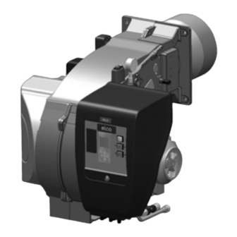
Page 4: Burner Description
General information EKEVO 6/EKEVO 7 Burner description Fuel oil pressure switch Power controller (option) Casing Photocell Burner tube Integrated switch cabinet Burner flange Air box Lifting rings Connector for inspection glass cooling Air pressure switch Electric motor Pump motor Y10 Actuator for air and gas flaps 102 Fuel oil pump Note: The construction principle for EKEVO 6-... -
Page 5: Installation Air Duct Connection, Rotating Air Box Ekevo 6/Ekevo 7
Installation EKEVO 6/EKEVO 7 Air duct connection Rotating air box for dimensions: see technical data * Rotation procedure of air box: see chapter «Servicing» 01/2016 - Art. Nr. 4200 1059 6100A... -
Page 6: General Information Regarding Burner Assembly
Installation General information regarding burner installation Tightening torques During installation, commissioning and maintenance, the following torques for screw connections must be observed. Max. tightening torques for accessories system, double gas valve G1/8 G1/4 G1/2 G3/4 3 Nm 8 Nm 15 Nm 35 Nm Siemens 7 Nm... -
Page 7: Boiler Lining For Gl-Ez3 Burner
Installation Boiler lining for GL-EZ3 burner Boiler lining The burner lining must be installed at a right angle to the burner tube. Possible trimming work (bevelling, rounding) as required for reverse boilers, for example, should done at a diameter not below 70% of the combustion chamber diameter. -
Page 8: Burner Assembly
Installation Burner installation thermocord, the operator should wear Burner flange seal (option 1) The surface of the The sealing tape in the accessories kit loose-fitting, long-sleeved clothing. In Seal corners with entire circumference sealing tape must be affixed to the burner as shown the event of high fibre dust must be sealed in the drawing below. -
Page 9: Burner Head Setting Data
Installation Burner head setting data externally-oriented radial gas and stabilisation holes tangential to the deflector 1st stage setting the ignition 2. stage electrodes 3. stage Ø a Ø b Ø c N6/EKEVO 6.2400 GL-EZ3 60,5 N6/EKEVO 6.2900 GL-EZ3 60,5 N7/EKEVO 7.3600 GL-EZ3 N7/EKEVO 7.4500 GL-EZ3 01/2016 - Art. -
Page 10: Combustion Components
Installation Combustion components Ignition electrodes adjustment data/check Note: If there are any ignition or flame detection problems, check the setting and dimensions of the electrodes. If the wear is too great, replace the electrodes. Gas ignition electrode a[mm] b[mm] c[mm] d[mm] N6/N7 57,3... -
Page 11: Installation
Installation Combustion components Installation Installing the combustion components • Check that the ring seal J1 is fitted and correct positioned on the gas flap flange. • Check the settings for the ignition electrode and burner head as shown. • Insert the combustion components into the flame tube, tighten the securing screws S3. -
Page 12: Gas Train
Installation Gas train Description of gas train with VGD... Description Gas train installation Gas train with VGD To fit the gas train supplied to the Gas trains with a Siemens VGD double Technical data: burner, the screw connections and seals valve are intended for the supply, main Types of gas: provided for this must be used (supplied... -
Page 13: Description Of Gas Train With Mbc
Installation Gas train Description of gas train with MBC... Description Gas train selection Gas train with MBC The gas fitting trains with Dungs MBC ... The gas train is defined on a system- Technical data: double gas valves MBC... are used for specific basis. -
Page 14: Basic Design
Installation Gas train Basic design Gas train to EN 676, low pressure 100 Burner 349 Servomotor 101 Impulse pipe gas pressure 120 Air flap Options in accordance with country-specific requirements: 141 Ball valve 143 Pressure gauge with pushbutton valve 142 Gas filter 147 Test burner with pushbutton valve 150 Gas control damper 148 Compensator... -
Page 15: Gas Train Components Description Of Double Gas Valve Vgd With Skp Servo Motors
Gas train components Description of double gas valve VGD with SKP servo motors Technical specifications VGD double gas valves with SKP actuators: Type of gas: Gasses in accordance with DVGW worksheet G 260/1, gas families 1, 2, 3 and biogas (H S content 0.1 vol.% max.), H Electrical data:... -
Page 16: Description Of Double Gas Valve Mbc
Gas train components Description of double gas valve MBC... (gas multiblock) Pressure taps MBC-300/ Technical data 700... Gas multiblock MBC-.../SE: Type of gas: Gases in accordance with DVGW worksheet G 260/1, gas families 1, 2, 3 Electrical data: 230 V -15% + 10%, other MBC-1200... -
Page 17: Overview Of Electrical Connection
Gas train components Overview of electrical connection Description of double gas valve MBC... (gas multiblock) Earthing in accordance with local Electrical connection MBC-300-1200 SE regulations. Electrical connection MBC-1900-7000 SE 01/2016 - Art. Nr. 4200 1059 6100A... -
Page 18: Changing Mbc-300-700-1200 Filter
Gas train components Replacing the MBC-300-700-1200 filter Adjusting the MBC-300-700-1200-SE pressure regulation component Filter inspection must be carried out at least once a year Replace filter if Δp between pressure port 1 and 2 > 10 mbar. Replace filter if Δp between pressure port 1 and 2 is twice as high as the measurement from the last inspection. -
Page 19: Setting Mbc-1900-5000-Se Pressure Regulating Component
Gas train components Adjusting the MBC-1900-7000-SE pressure regulation component 5. Apply a security seal to the adjusting Adjusting the MBC-1900-7000-SE screw (see below). pressure regulation component 1. Open the protective caps. Optimum combustion and ignition safety must be ensured. 2. Start the burner, correction of set values possible while burner in operation (see figure). -
Page 20: Gas Filter Test Burner
Gas train components Gas filter Test burner Installation and mounting of the gas filter The filter must be installed in a horizontal pipe. The vertical position of the cover makes cleaning easier. Be aware of the gas flow direction (see arrow on the filter housing). -
Page 21: Gas Pressure Switch
Gas train components Gas pressure switch Gas pressure switch GW...A5/A6 Gas pressure switch A5 Technical data: The gas pressure switch is designed to monitor the gas flow pressure. It can be Type of gas: used for monitoring either falling Gases according to DVGW Worksheet pressure (minimum) or rising pressure G 260/1, gas families 1, 2, 3 (maximum, specified for equipment... -
Page 22: Installation Air Pressure Switch
Installation Air pressure switch in other important gas consumption Air pressure switch The air pressure switch is provided for countries. monitoring the pressure of the combustion air fan. Pressure switch N.B.(Gas and air pressure switches) LGW... is suitable for switching an The pressure switches must be set in electrical circuit or for switching it on or off accordance with the specifications. -
Page 23: Hydraulics Fuel-Oil System Diagram
Hydraulics Fuel-oil system diagram With feeder pump Forced draught burner Fuel-oil filter Shut-off valve Oil level indicator Intake valve Tank Leak warning device Fast-closing valve Fill pipe Limit value encoder Vent line Pump installation Pressure maintaining valve Direct suction Forced draught burner Fast-closing valve Fuel-oil filter Fill pipe... -
Page 24: General Information Regarding The Fuel-Oil System
Hydraulics General information regarding the fuel-oil system Fuel-oil hydraulics diagram 100 Burner 101 Fan 118 Nozzle 120 Air flap 121 Fuel oil pressure switch 143 Pressure gauge (optional) 144 Safety valve 175 Filter 176 Pump 178 Solenoid valve, supply line 200 Measure nipple fuel oil suction pressure 349 Servomotor... -
Page 25: Commissioning Fuel-Oil Pressure Switch
Commissioning Fuel-oil pressure switch When the setting procedure is complete, Fuel-oil pressure switch Fuel-oil pressure switches are used to the setting button must be returned for monitor burners to ensure that they do reasons of safety. not exceed or fall below specific fuel-oil A seal must be applied to the pressure pressures. -
Page 26: General Information Regarding Fuel Oil System
Commissioning General information regarding fuel oil system Fuel oil connection Fuel oil pressure regulator (supply N6/EKEVO 6 Hoses are used to make a connection to line) The supply pressure is regulated by the the fuel oil tubes or the gate valves. To pressure regulator fitted in the pump prevent kinks and therefore any risk of and, depending on the burner output... - Page 27 Commissioning Pump type J7 Areas of application - Light, medium-grade oil Pumping capacity - Two-line system. Capacity (l/hr) - Generally connected to the solenoid valve in the nozzle line Description of Functions The gearbox draws the fuel oil from the tank through the built-in filter and supplies it under pressure to the valve which controls the oil pressure for the...
- Page 28 Commissioning Pump type J7 General Attachment Flange attachment as per EN 225. Model 1000 Model 1001/1002 Connections Conical Cylindrical in acc. with ISO 228/1 Supply line and backflow 1/4" NPTF G 1/2 Nozzle outlet 1/8" NPTF G 1/4 Pressure test connection 1/8"...
- Page 29 Commissioning Pump type TA3 Areas of application Pumping capacity Capacity (l/hr) - Domestic oil and heavy-grade oil (for use with kerosene, please contact SUNTEC) - Two-line system. Description of Functions The gearbox draws the fuel oil from the tank and supplies it under pressure to the valve which controls the oil pressure for the nozzle line.
- Page 30 Commissioning Pump type TA3 General Attachment Flange attachment Connections Cylindrical in acc. with ISO 228/1 Supply line and backflow G 1/2 Nozzle outlet G 1/2 Pressure test connection G 1/4 Vacuum test connection G 1/4 Shaft Ø 12 mm Bypass-plug Used in the vacuum connection for two-line installaiton Weight...
-
Page 31: Nozzle Line, 3-Stage
Commissioning Nozzle line, 3-stage The nozzles for the 3-stage nozzle line All the Monarch and Steinen nozzles are selected so as to meet the maximum have permanent labels containing the performance requirements of the boiler following information (subject to change with the best possible control range and and based on CEN standards): high combustion quality overall. - Page 32 Commissioning Nozzle line, 3-stage Oil throughput with pump pressure in bar STEINEN Oil through- Kg/hr put at 7 bar Pressure in bar 10.00 38.28 41.93 45.29 51.36 54.14 11.00 42.11 46.13 49.82 56.50 59.56 12.00 45.94 50.32 54.36 61.64 64.98 13.00 49.77 54.52...
-
Page 33: Burner Control Unit
Commissioning Burner control unit Description The electronic burner controller is a programmable automatic firing device with an integrated electronic compound controller. There may be additional functions, depending on the equipment and model. The following burner-specific controllers are used: Burner controller BT 340 Manufacturer Lamtec... -
Page 34: Electrical Cabinet Door Construction
Commissioning Electrical cabinet door construction Manual terminal (display) for controlling the burner control unit N6/N7 Switch for fuel selection / light indicator control voltage Power control +/- Switch manual / automatic Switch on site / remote Power controller (option) EKEVO 6/EKEVO 7 Note: The above information is for standard equipment. -
Page 35: Servomotor Ste
Commissioning Servomotor STE Servomotor STM40 The BT300 electronic control system works with the STE4.5 numerically controlled servomotor. For monitoring the function and direction of rotation, there is a driver with digital feedback via encoder disc. Observe the commissioning procedure for BT300. The connection is documented in the burner wiring diagram. -
Page 36: Flame Sensor
Commissioning Flame sensor The flame sensor is a component of the Depending on the requirements of the In some gas burners, flame monitoring flame monitoring system. burner and fuels, the flame sensor may is achieved by means of ionisation. In be an optical sensor that monitors light this case, no optical flame sensor is In interaction with the automatic... - Page 37 Commissioning Flame sensor Table: cell setting Burner Etamatic OEM BT 300 FFS 08 (IR) QRA 2 FFS 08 (IR) (PED option A [mm] Angle α [°] A [mm] Angle α [°] A [mm] Angle α [°] N6/EKEVO 6 N7/EKEVO 7 Flame monitoring &...
-
Page 38: Gas Fitting Connection, Electrical Connection
Commissioning Gas fitting connection Electrical connection Checks before commissioning The electrical connection of the burner All electrical installation and Gas fitting connection The connectors on the burner must be may only be performed by authorised connection work must only be carried used for connecting the gas valve. -
Page 39: Gas Connection
Commissioning Gas connection Gas connection Gas properties Leak test The gas lines and trains should be Prior to any installation work make sure The fitted gas train must be leak tested installed and taken into operation in to obtain the following data from the gas on the system in accordance with accordance with the applicable supply company:... -
Page 40: Fuel-Air Compound Control
Commissioning Fuel-air compound control requirement (temperature or pressure Fuel-air compound control Equipment option: speed control This compound pneumatic control level). The fuel volumes of the stages The burners can be equipped with a system with precision-adjustment are switched on or off once. As with the speed controller as an option. -
Page 41: Burner Power Adjusting Sequence
Commissioning Burner power adjusting sequence The burner is operated and adjusted (see chapter entitled Preventilation) over the entire load range (see also using a handheld device or a PC (serial • Set starting heat output of burner to chapter entitled Gas pressure control). interface). -
Page 42: Inspection
Commissioning Inspection Before commissioning the system for Fuel-oil commissioning Gas commissioning the first time, the following • Open all the gate valves on the fuel-oil • Connect the test devices for the gas inspections must be carried out: supply system. head pressure on the test connection •... -
Page 43: Preventilation
Commissioning Preventilation Assuming the conditions in the area or Preventilation: Please note: the boiler unit in the case of electronic Care must be taken to ensure that the are the same for preventilation and compound controls (BT300/ boiler system is adequately preventilated. -
Page 44: Gas Start-Up Mode Gas Operating Mode General Safety Functions
Commissioning Gas start-up mode Gas operating mode General safety functions After the pre-ignition time, the main gas Depending on the heat demand, the Gas start-up mode As soon as the furnace is required to valves are open and the gas comes out output controller will actuate the supply heat, the burner control circuit will from injectors where it is mixed in the... -
Page 45: Fuel-Oil Start-Up Mode Fuel-Oil Operating Mode General Safety Functions
Commissioning Fuel-oil start-up mode Fuel-oil operating mode General safety functions sent to the automatic firing device via the The burner is always shut down from the Fuel-oil start-up mode If heat is required by the furnace, the part load setting. flame monitor and must remain in place electronic combustion manager As far as possible, the air flap is closed... -
Page 46: Servicing Maintenance
Servicing Maintenance tube for leaks located in the burner (e.g. the parts of Burner and boiler servicing must only - Check the ignition electrodes and the combustion head) before closing the be carried out by a professionally ignition sparking. Clean and readjust if qualified heating engineer. -
Page 47: Maintenance Replacing The Control Unit
Servicing Maintenance Replacing the control unit parts. Using defective or damaged com- tion, and may even cause injury (risks of Warning! Replace any damaged or defective com- ponents may cause malfunctioning and serious or fatal injury). ponents! Replace safety components hazardous operation. - Page 48 Servicing Maintenance Checking the combustion N6/N7 components • N6/N7 : Unscrew the 2 screws S, remove the burner cover. • EKEVO : Unscrew the 4 screws W, remove the housing cover. • N6/N7 : Remove the 7 screws W to remove the combustion components access cover.
-
Page 49: Checking / Installing The Combustion Components
Servicing Maintenance Checking / installing the combustion components Filter replacement Checking the flue gas temperature • Check the flue gas temperature at • The multiblock filter screen (only Important regular intervals. applies to MBC...) must be checked at After every operation: check the •... -
Page 50: Rotation Procedure Of Air Box Ekevo 6/Ekevo 7
Servicing EKEVO 6/EKEVO 7 Rotation procedure of air box Rotation procedure of air box Remove the flexible air hose. Disassemble the servomotor from the air flap and fasten it to the casing. Disassemble the cover of the air box. Unfasten the air box support, swing it towards the new desired position and fasten it again (rotation possible in 45°... -
Page 51: Fan Wheel Setting
Servicing Fan wheel setting The fan wheel can be stopped at any Fan wheel installation position on the motor shaft. - Clean all the bare surfaces and To achieve a high slipping torque, the degrease them surface of all the parts to be inserted into - Insert the discs and bushings into one one another must be clean and grease- another, align the holes. - Page 52 Servicing Fan wheel setting Because of its design the turbine can be fitted to the drive shaft only in a fixed position. The same position is consequently ensured every time it is assembled. There is no need for any further adjustment of the axial cover through the air conveyor.
-
Page 53: Exhaust Gas Measurements
Servicing Exhaust gas measurements the permissible smoke spot number in the Exhaust gas measurement Gas temperature 15 °C In order to ensure efficient and fault-free exhaust gas must not be exceeded. Standard pressure 1013 mbar operation, the burner must be adjusted with reference to the specific system. -
Page 54: Diagnosing And Remedying Faults
Servicing Exhaust gas measurements Diagnosing and remedying faults Exhaust gas loss Natural Town Exhaust gas loss by way of free heat will Fuel-oil EL Fuel-oil S Liquid gas occur as a result of the temperature difference between the fuel-air mixture 0.50 0.490 0.370... - Page 55 Servicing Diagnosing and remedying faults 8. Cleaning and lubricating 4. Nozzle - uneven 6. Combustion components - instructions atomisation poor combustion values Depending on the cleanliness status of heavy internal oil deposits the combustion air, the fan impeller, Cause Remedy or heavy coke deposits ignition electrodes, flame sensors and (fuel-oil mode)
-
Page 56: Faults
Servicing Faults The start-up program will be initiated Smell of gas, danger of gas If system faults occur, proceed with • Shut down the burner and should be carefully monitored. checking the basic conditions for • Close the gas shut-off valve proper operation of the system. -
Page 57: Declaration Of Conformity
01/2016 - Art. Nr. 4200 1059 6100A... - Page 58 01/2016 - Art. Nr. 4200 1059 6100A...
-
Page 59: Manufacturer Certification In Accordance With 1. Bimschv
01/2016 - Art. Nr. 4200 1059 6100A... - Page 60 01/2016 - Art. Nr. 4200 1059 6100A...
- Page 61 01/2016 - Art. Nr. 4200 1059 6100A...
- Page 62 01/2016 - Art. Nr. 4200 1059 6100A...
- Page 63 01/2016 - Art. Nr. 4200 1059 6100A...
- Page 64 Made in EU. Non contractual document. 01/2016 - Art. Nr. 4200 1059 6100A...
Need help?
Do you have a question about the EKEVO 6/N6.2400 GL-EZ3 and is the answer not in the manual?
Questions and answers