Table of Contents
Advertisement
Quick Links
Order parts online
www.follettice.com
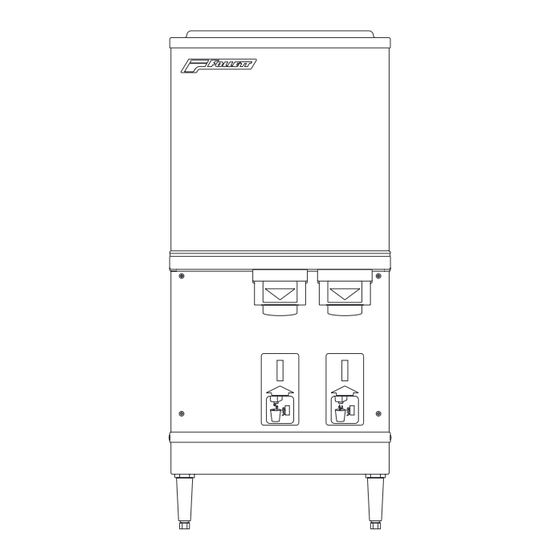
C125A
countertop dispenser
Installation, Operation and Service Manual
countertop dispenser with
SensorSAFE
Following installation, please forward this manual
to the appropriate operations person.
801 Church Lane • PO Box D • Easton, PA 18044
Toll free (800) 523-9361 • (888) 2-FOLLETT
(610) 252-7301 • Fax (610) 250-0696 • www.follettice.com
Ice and Water Dispensers
C125A
™
actuation (shown
with legs accessory)
12 Series
H125A
wall mount dispenser (available
with or without drain pan)
U L
®
®
207805R02
Advertisement
Table of Contents
Troubleshooting

Related Manuals for Follett C125A


Summary of Contents for Follett C125A
- Page 1 Following installation, please forward this manual to the appropriate operations person. 801 Church Lane • PO Box D • Easton, PA 18044 Toll free (800) 523-9361 • (888) 2-FOLLETT ® ® (610) 252-7301 • Fax (610) 250-0696 • www.follettice.com...
-
Page 3: Table Of Contents
Table of contents Before you begin ..................Specifications ....................Installation procedures ................Installing countertop dispensers without legs ......Installing countertop dispenser with legs accessory ....Installing wall mount dispensers ..........User information ..................Cleaning and sanitizing procedures .......... Dispenser cleaning ..............Icemaker cleaning and sanitizing .......... -
Page 4: Before You Begin
Before you begin • After uncrating and removing all packing material, inspect the equipment for concealed shipping damage. If damage is found, notify your shipper immediately and contact Follett Corporation for help in filing a claim, if necessary. • Check your paperwork to determine which model dispenser you have. Follett model numbers are designed to provide information about the type and capacity of Follett ice dispensing equipment. -
Page 5: Specifications
50°F/10°C Min. (Best performance below 80˚F/27˚C) Water temp 90°F/32°C Max. 40°F/4°C Min. (Best performance below 70˚F/21˚C) Water pressure 70 P.S.I. Max. 10 P.S.I. Min. Plumbing specifications C125A H125A Dispenser drain 3/4" FPT 3/4" FPT Water inlet 3/8" FPT 3/8" FPT Note: Water shut-off recommended within 10 feet (3m) of dispenser. -
Page 6: Installation Procedures
Installation procedures Before you begin • All dispensers must be installed level in both directions to ensure proper operation. • Required service and ventilation clearances: 6" (153mm) on right side of dispenser, 12" (305mm) at top. • Countertop units installed without legs provide the option of taking utilities out bottom or back of dispenser (on wall mount units and countertop units with legs, utilities exit out back). -
Page 7: Installing Countertop Dispenser With Legs Accessory
Rear exiting utilities Fig. 2 Bottom exiting utilities Fig. 3 (countertop units) (countertop units) (b-1) Move pipe plug to back of unit 3/4" FPT drain (b-2) 16" (407mm) 11.7" (298mm) 8.1" (206mm) 1.5" (39mm) (c) Remove poly tubing and 3/8" FPT fitting for water inlet water inlet .9"(23mm) -
Page 8: Installing Wall Mount Dispensers
Fig. 5 Wall mount bracket and fastener requirements Installing wall mount dispensers wall mounting Wall mount models require 30" (762mm) bracket deep counters and front of sinks must be installed no more than 2" (51mm) from front of counter. Supporting wall must be reinforced to handle dispenser weight (185 lbs/83.9kg). - Page 9 Fig. 8 Wall mount unit bottom panel assembly Fig. 9 Wall mount bottom view support bracket 3/4" FPT 3/8" FPT bottom panel drain water inlet screw Fig. 10 Front view of wall mount bracket – utility location water and 3/8" copper 3/4"...
-
Page 10: User Information
User information How the dispenser works Follett’s 12 series automatic load ice and water dispensers are equipped with Follett’s 400 lb (181kg)/day icemaker. In Follett’s continuous icemaking process, water freezes to the inside walls of the evaporator. A rotating stainless steel auger carries the ice to the top of the evaporator where it is compressed and extruded through an outlet port. -
Page 11: Icemaker Cleaning And Sanitizing
Cleaning of the condenser can usually be performed by facility personnel. Cleaning of the icemaker system in most cases should be performed by your facility’s maintenance staff or a Follett authorized service agent. Regardless of who performs the cleaning, it is the operator's responsibility to see that this cleaning is performed according to the schedule below. -
Page 12: Start-Up Following Cleaning
Most ice machine cleaners contain citric or phosphoric acid which can cause skin irritation. Read caution label on product and follow instructions carefully. 7. Plug evaporator drain hose and pour part of cleaning solution into reservoir, filling almost to overflowing. 8. -
Page 13: Service Information
The icemaking process Follett icemakers use a wrapped tube evaporator and operate on a continuous freezing cycle. Water is supplied to the evaporator from the water reservoir where the water level is controlled by a float valve. This valve also shuts off the water supply when the icemaker is not running. -
Page 14: Wiring Diagram - Lever Model
Wiring diagram – lever model... -
Page 15: Wiring Diagram - Sensorsafe Model
Wiring diagram – SensorSAFE model ™ NEUTRAL... -
Page 16: Icemaker Operational And Diagnostic Sequences
Icemaker operational and diagnostic sequences The wiring diagrams that follow illustrate the circuitry of Follett icemakers used with 12 series ice dispensers. Both normal operation (Stages 1 - 6) and non-normal diagnostic sequences showing torque-out (Stages 7 - 10) for use in troubleshooting are shown. - Page 17 Normal operation – Stage 2 The water sensor verifies water in the float. The Water OK LED (WTR) comes on. At the same time, the gearmotor, compressor and condenser fan motor come on, lighting the Drive LED (DR) and compressor LED (C). The compressor is started through a current style relay that is pulled in by the initial high current draw of the compressor.
- Page 18 Normal operation – Stage 4 Once the ice level control opens, the B-E LED goes out. After a 10 second delay the LED (C), compressor and fan motor go off. (Should the ice level control not remain open for 10 seconds, the icemaker will continue to run.) The gearmotor continues to run for 60 seconds.
- Page 19 Normal operation – Stage 6 When the dwell time of 20 minutes has expired, the B-T LED goes off. The icemaker will go through the normal start up sequence when the bin level control signals the control board for ice. The WTR LED will remain on as long as the water sensor in the float reservoir senses water.
- Page 20 Diagnostic sequence – Stage 8 When the 20M LED goes off, the 60 Minute Timer LED (60M) comes on. The 60M LED will remain on for 60 minutes from restart. A lighted 60M LED tells the technician that the icemaker has experienced an over-torque condition.
-
Page 21: Refrigeration Cycle Diagram
Diagnostic sequence - Stage 10 If the water level in the float reservoir drops to an unacceptable level, the WTR LED will go out, shutting the icemaker off. Also, the BT LED will come on, preventing the icemaker from restarting for twenty minutes. If water is restored, the WTR LED will come back on and flash to alert the technician that water to icemaker has been lost. -
Page 22: Icemaker Capacity Chart
Air-cooled icemaker capacity/24 hours Ambient Air Temperature °F/°C F° 60° 70° 80° 90° 100° 110° C° 16° 21° 27° 32° 38° 43° 50° lbs. 10° 60° lbs. 16° 70° lbs. 21° 80° lbs. 27° 90° lbs. 32° lbs. 100° 38° 110°... -
Page 23: Refrigeration System Data And Requirements
Refrigerant replacement requirements 1. Non-contaminated refrigerant removed from any Follett refrigeration system can be recycled and returned to the same system after completing repairs. Recycled refrigerant must be stored in a clean, approved storage container. If additional refrigerant is required, virgin or reclaimed refrigerant that meets ARI standard 700-88 must be used. -
Page 24: Dispenser Troubleshooting - Lever/Sensorsafe Models
Ice capacity test Icemaker production capacity can only be determined by weighing ice produced in a specific time period. 1. Remove top panel and hopper lid of unit. 2. Run icemaker for at least 15 minutes. 3. Weigh and record weight of container used to catch ice. 4. -
Page 25: Troubleshooting - Sensorsafe Board And Sensors
Troubleshooting the dispenser – SensorSAFE ™ models Problem: Does not dispense ice and/or water Action LED status Solution ICE/WTR 1. Check LEDs on Check circuit breakers and power switch. Restore control board. power or replace defective switch. Press clean switch on lower left side of electrical enclosure to return board to normal operation. -
Page 26: Icemaker Troubleshooting
4. Precool water and/or correct high temperature. ambient temperature. 5. Improper exhaust air provisions. 5. Provide proper exhaust air 6. Faulty expansion valve. provisions per Follett 7. Low refrigerant charge. specifications. 8. Superheat incorrect. 6. Replace expansion valve. 9. Inefficient compressor. - Page 27 3. Clogged or dirty condenser coil. 3. Clean condenser coil. 4. Improper ventilation. 4. Provide inlet and exhaust air provisions per Follett specifications. 5. Defective compressor. 5. Replace compressor. 9. Unit runs but not making 1. Clogged or dirty condenser coil.
-
Page 28: Disassembly And Replacement Instructions
Disassembly and replacement instructions Dispense chute removal stud assembly 1. Remove top cover. 2. Remove stainless front cover. 3. Slide plastic dispense chute cover up and out to agitator remove. 4. Remove four (4) push fasteners holding dispense tube in place and remove tube. spacer Dispense wheel and drive bar removal baffle... - Page 29 Evaporator disassembly Note: The upper bearing, lower bearing and auger assemblies must be replaced as assemblies. The bottom and top bearing assemblies cannot be field assembled to factory specifications. 1. Disconnect power to icemaker. 2. Shut off water to icemaker. 3.
- Page 30 Panel removal top cover front cover screw Top cover: Lift cover up and off Velcro strips. Front cover: Remove 2 screws. Lift cover up and forward to unhook from keyhole slots and clear tabs on bottom of cover. back panel screw right hand left hand...
- Page 31 Thermostat and ice transport tube replacement ice tube retainer ice tube gasket Ice transport tube: tube may extend a maximum capillary of 1/4" into ice bin 3" tube bracket 2" .50 TYP Thermostat: hand bend cap tube end as shown Top view Ice transport tube replacement Soak end of transport tube in hot water to soften.
-
Page 32: Parts
Parts Dispenser exterior Part # Description Reference # 502393 Cover, front 502401 Cover, dispense assembly, water 502400 Cover, dispense assembly, ice 502402 Louver, intake 502412 Grille, drain pan Not shown 502411 Drain pan, plastic 502410 Drain pan assembly (includes base, pan and grille) 502394 Panel, rear 502399... -
Page 33: Wheelmotor And Drive System
Wheelmotor and drive system cover interlock switch Top view Part # Description Reference # 502580 Motor, wheel (includes 502537) 502384 Drive shaft extension 502385 Coupling (includes key) 501273 Key, 1/8" sq x 1-1/4 lg 502414 Baffle, ice (securing hardware included) 502387 Wheel, agitator 502390... -
Page 34: Dispense Chute And Splash Panel - Lever Models
Dispense chute and splash panel — lever model water solenoid assembly Part # Description Reference # 502513 Chute assembly, ice 502249 Chute, water 502247 Bracket, dispense chute (includes four (4) 502057 fasteners) 502417 Lever 501100 Thumbscrew 502409 Switch, dispense, water/ice (includes nut, boot and spacer) 502418 Boot, dispense switch button (mounts over the dispense button) 502057... -
Page 35: Dispense Chute And Splash Panel - Sensorsafe Models
Dispense chute and splash panel — SensorSAFE ™ model Part # Description Reference # 502513 Chute assembly, ice 502249 Chute, water 502247 Bracket, dispense chute (includes four (4) 502057 fasteners) 502251 Graphics, ice lens 502252 Graphics, water lens 502241 Assembly, sensor and mounting block (includes 502239 and 502240) 502239 Block, sensor mounting 502240... -
Page 36: Icemaker Components
Cord and plug, power Water filter kits and cartridge Part# Description AFSYSTMFL43 Follett QC4-FL4S water filter system (includes FL4S primary cartridge and head. coarse pre-filter and head, pressure gauge, flushing valve; assembled and installed on mounting bracket) AFCARTFL4S Follett FL4S primary replacement cartridge... - Page 37 Right side view Rear view OPERATE UNIT WITH PANELS REMOVED. Top view Left side view (lower section)
-
Page 38: Electrical Components
Electrical components Side view Top view Part # Description Reference # 501586 Capacitor, start, compressor, 115V, 60Hz 501588 Relay, start, compressor, 115V, 60Hz 502331 Board, control circuit, 115V, 60Hz 502116 Water sensor 502392 Switch, on/off, compressor 502209 Switch, rocker, power 502209 Switch, rocker, bin signal 502409... -
Page 39: Evaporator
Evaporator Part # Description Reference # 500486 Coupling, vee band, includes nut 501862 Bearing assembly, top 502081 Loop, ice compression, padded (For non-thick-walled evaporators, call service department before ordering) 502110 Loop, ice compression, beveled 502219 Auger, double chamfered Detail - ice compression 502107 Evaporator (includes 502110) -
Page 40: Gearbox And Motor Assembly
Grease, Chevron, SRI-2, 14 oz tube 502538 Carton and foam packs 801 Church Lane • PO Box D • Easton, PA 18044 Toll free (800) 523-9361 • (888) 2-FOLLETT 207805R02 ® ® (610) 252-7301 • Fax (610) 250-0696 • www.follettice.com...
Need help?
Do you have a question about the C125A and is the answer not in the manual?
Questions and answers