Table of Contents
Advertisement
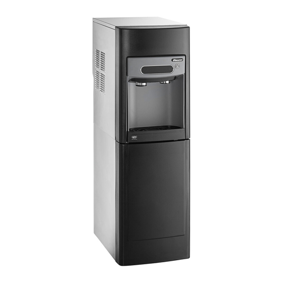
Countertop and Freestanding Ice and Water
Dispenser with Chewblet
Ice Icemaker
®
7CI100A, 7FS100A, 15CI100A, 15FS100A
Installation, Operation and Service Manual
Serial numbers E01087 to J57179
7CI100A
7FS100A
15CI100A
15FS100A
Following installation, please forward this manual
to the appropriate operations person.
801 Church Lane • Easton, PA 18040, USA
Order parts online:
Toll free (877) 612-5086 • +1 (610) 252-7301
www.follettice.com
www.follettice.com
00951640R09
Advertisement
Table of Contents

Related Manuals for Follett 15 Series


Summary of Contents for Follett 15 Series
- Page 1 Countertop and Freestanding Ice and Water Dispenser with Chewblet Ice Icemaker ® 7CI100A, 7FS100A, 15CI100A, 15FS100A Installation, Operation and Service Manual Serial numbers E01087 to J57179 7CI100A 7FS100A 15CI100A 15FS100A Following installation, please forward this manual to the appropriate operations person. 801 Church Lane •...
-
Page 2: Table Of Contents
15 Series Detailed Drawing . . . . . . . . . . . . . . . . . . -
Page 3: Welcome
After uncrating and removing all packing material, inspect the equipment for concealed shipping damage . If damage is found, immediately notify the shipper and contact Follett Corporation so that we can help in the filing of a claim, if necessary . If needed, the serial number of your dispenser can be found by removing the drip tray ❶... -
Page 4: Important Safety Information
Important Safety Information ––––––––––––––––––––––––––––––––––––––––– Please read and adhere to the following safety information while installing, using, or servicing your Follett Ice Dispenser . 1 . Always disconnect power before servicing the dispenser . 2 . Ice is slippery . Maintain counters and floors around dispenser in a clean and ice-free condition . -
Page 5: Specifications
Specifications ––––––––––––––––––––––––––––––––––––––––––––––––––––– Water WARNING! Connect to potable water supply only. § Water Mineral Content: – TDS: greater than 5 ppm (mg/l) but less than 400 ppm (mg/l) – Hardness: Less than 200 mg/l (12 gpg) § Not recommended for use with softened water Clearances §... -
Page 6: Series Detailed Drawing
Specifications –––––––––––––––––––––––––––––––––––––––––––––– (continued) 7 Series Detailed Drawing Countertop models 14.50" (36.8 cm) 14.5" (36.8 cm) NEMA 5-15 right angle 17.50" 17.50" (44.5 cm) (44.5 cm) 6.88" 6.75" (17.5 cm) (17.2 cm) power cord 22.12" (56.2 cm) 1/4" MPT 2.50" 3.00" (6.4 cm) (7.6 cm) water inlet... -
Page 7: Series Detailed Drawing
Specifications –––––––––––––––––––––––––––––––––––––––––––––– (continued) 15 Series Detailed Drawing Countertop models 14.50" (36.8 cm) 23.50" (59.7 cm) 14.50" (36.8 cm) 22.50" NEMA 5-15 (57.2 cm) right angle 22.50" (57.2 cm) power cord 6.88" 6.75" (17.5 cm) (17.2 cm) 22.12" (56.2 cm) 1/4" MPT 2.50"... -
Page 8: Installation
Fig . 1 The 7 Series countertop model is designed to fit on counters underneath countertop models standard mounted cabinets, this does not apply to 15 Series models . See minimum 3" (77 mm) page 4 for dimensions . Installation instructions for freestanding model... -
Page 9: Freestanding Installation
Installation ––––––––––––––––––––––––––––––––––––––––––––––––– (continued) Optional Leg Accessory Installation Fig . 3 CAUTION! Use caution when tipping the dispenser during leg installation. Do not lay unit on back or side. DO NOT EXCEED 30° angle. Tipping more than 30° can result in compressor malfunction. 1 . - Page 10 * If your dispenser has the internal water filter option, the water filter must be installed for the dispenser to operate . Because internal components will need to Plug be accessed for both procedures, Follett recommends installing the water filter just prior to initial sanitizing . Valve Connect power supply .
- Page 11 If your dispenser has the internal water filter option, the water filter must be installed for the dispenser to operate . Because internal components will need to be accessed for both procedures, Follett recommends installing the water filter just prior to initial sanitizing .
-
Page 12: Maintenance/Cleaning Mode
Maintenance/Cleaning Mode ––––––––––––––––––––––––––––––––––––––––– Cleaning Mode (Dispensing Disabled) - Use when cleaning surface Fig . 10 Entering Cleaning Mode disables the User Interface and allows you to clean the outside of the dispenser without accidentally dispensing water or ice . 1 . To enter Cleaning Mode, press and immediately release the maintenance/clean switch (Fig . -
Page 13: Filter Display Indicator Activation
Filter Display Indicator Activation ––––––––––––––––––––––––––––––––––––– Fig . 12 If you purchased your dispenser with a Follett filter, the filter display indicator activation has been preset at the factory . If you are using an “after market filter,” an adjustment may be made to activate the “Fresh Filtered Ice &... -
Page 14: Nsf-Approved Cleaning And Sanitizing Procedure
11 . 7 Series: Mix 21 oz . (0 .621 L) or 3 packets SafeCLEAN Plus with three gallons (11 .4 L) of water . 15 Series: Mix 42 oz . (1 .24 L) or 6 packets SafeCLEAN Plus with six gallons (22 .7 L) of water 12 . -
Page 15: Service
LEDs will turn off, and the machine will resume normal operation . Service 8000 hour bushing check (call Follett technical service group at (877) 612-5086 or +1 (610) 252-7301) . Maintenance Yellow Enter Maintenance Mode by pressing and holding maintenance/clean switch for 5 seconds . -
Page 16: Evaporator Disassembly
Service –––––––––––––––––––––––––––––––––––––––––––––––––––– (continued) Evaporator Disassembly Fig . 16 1 . Disconnect power from the dispenser . 2 . Turn off water supply to dispenser . 3 . Remove (unscrew) chrome ice dispenser chute (Fig . 16 .1) . 4 . Remove the drip tray (Fig . 16 .2) . 5 . - Page 17 Service –––––––––––––––––––––––––––––––––––––––––––––––––––– (continued) 10 . Unplug the gear motor (three connectors) (Fig . 16) . Fig . 17 11 . Remove ground screw connection . 12 . Remove gear motor: Fig . 18 § Remove M6 allen screw, retainer, spacer and key (Fig . 18 .1) . §...
- Page 18 Service ––––––––––––––––––––––––––––––––––––––––––––––––––– (continued) 15 . Remove M6 socket head allen screw (Fig . 20 .1) . Fig . 20 16 . Remove compression nozzle retainer (Fig . 20 .2) . 17 . Remove compression nozzle (Fig . 20 .3) . 18 . Remove main housing: Fig .
-
Page 19: Evaporator Assembly
Service ––––––––––––––––––––––––––––––––––––––––––––––––––– (continued) 21 . Remove and discard mating ring and seal (Fig . 23 .1) . Fig . 23 22 . Carefully remove auger (Fig . 23 .2) . WARNING! Use caution when removing auger. The auger is very sharp - handle with care to avoid personal injury. Evaporator Assembly Fig . - Page 20 Service ––––––––––––––––––––––––––––––––––––––––––––––––––– (continued) Fig . 26 Install compression nozzle: § Remove and inspect compression nozzle O-ring seal . Replace if damaged in any way . § Clean O-ring groove . Lubricate O-ring with Petro-gel and reinstall . § Install compression nozzle (Fig . 26 .1) . §...
- Page 21 Service ––––––––––––––––––––––––––––––––––––––––––––––––––– (continued) 11 . Use screwdriver to orient auger shaft to align with motor Fig . 29 shaft keyway (Fig . 29 .1) . 12 . Install key into keyway (Fig . 29 .2) . 13 . Install spacer, ensure that key is captured in slot Fig .
- Page 22 Service ––––––––––––––––––––––––––––––––––––––––––––––––––– (continued) 16 . Install screw and tighten (Fig . 32 .1) . Fig . 32 17 . Plug in gear motor (Fig . 33) . Fig . 33 § BLUE to BLUE § BLACK to BLACK § WHITE to WHITE §...
-
Page 23: Water Feed Schematic
Service –––––––––––––––––––––––––––––––––––––––––––––––––––– (continued) Water Feed Schematic Evaporator Float Water Chute (optional) Water Solenoid Valve Filter (optional) (optional) Water Solenoid Valve Dispenser and Icemaker 7CI100A/7FS100A, 15CI100A/15FS100A... -
Page 24: Bin Melt Water/Evaporator Feed/Clean Out System Schematic
Service –––––––––––––––––––––––––––––––––––––––––––––––––––– (continued) Bin Melt Water/Evaporator Feed/Clean Out System Schematic Storage Bin Vent System Schematic Storage Bin Vent Tube Reservoir Dispenser and Icemaker 7CI100A/7FS100A, 15CI100A/15FS100A... -
Page 25: Refrigeration Schematic
Service –––––––––––––––––––––––––––––––––––––––––––––––––––– (continued) Refrigeration Schematic CONDENSER FILTER-DRIER CAP TUBE COMPRESSOR EVAPORATOR ACCUMULATOR LOW PRESSURE LIQUID HIGH PRESSURE VAPOR HIGH PRESSURE LIQUID LOW PRESSURE VAPOR Dispenser and Icemaker 7CI100A/7FS100A, 15CI100A/15FS100A... -
Page 26: Condenser Fan Motor Removal (7 Series Shown)
Service –––––––––––––––––––––––––––––––––––––––––––––––––––– (continued) Condenser Fan Motor Removal (7 Series Shown) Dispenser and Icemaker 7CI100A/7FS100A, 15CI100A/15FS100A... -
Page 27: User Interface Display Identification
. Exit Maintenance Mode by pressing and holding maintenance/clean switch until no longer displays . Service - Call Follett Technical Service Group at 8000 hr (877) 612-5086 or +1 (610) 252-7301 . bushing check The flashing wrench indicates that the 8000 hr bushing check is required . - Page 28 . Internal leak in Locate leak and repair - Press reset dispenser on control board . Contact Follett if icemaker is leaking . Sleep mode Press either dispense button to return to normal operation .
-
Page 29: Electrical Wiring Diagram
Service –––––––––––––––––––––––––––––––––––––––––––––––––––– (continued) Electrical Wiring Diagram Dispenser and Icemaker 7CI100A/7FS100A, 15CI100A/15FS100A... -
Page 30: Parts
Parts ––––––––––––––––––––––––––––––––––––––––––––––––––––––––––––– 7 Series Exterior Dispenser and Icemaker 7CI100A/7FS100A, 15CI100A/15FS100A... - Page 31 Parts –––––––––––––––––––––––––––––––––––––––––––––––––––––– (continued) Exterior Reference # Description Part # Drip Tray Assy 00957613 Panel, Front Assy - Includes Water Nozzle and Plug 00957621 Chute, Water (water option) 00957688 Panel, Left 00932806 Panel, Right 00932798 Panel, Top 00957654 Panel, Rear 00933911 Screw, M5 x 12 Phillips 00931931 Not Shown...
-
Page 32: Series Interior
Parts –––––––––––––––––––––––––––––––––––––––––––––––––––––– (continued) 7 Series Interior Dispenser and Icemaker 7CI100A/7FS100A, 15CI100A/15FS100A... - Page 33 Parts –––––––––––––––––––––––––––––––––––––––––––––––––––––– (continued) Interior Reference # Description Part # Valve, Dispense Solenoid (water option) 00957704 Switch, Cleaning 00957712 Drain/Feed Tube with Cap 00957720 Valve, Failsafe Solenoid 00957738 Compressor with Mounting Hardware 00958009 Condenser 00958017 Condenser Fan and Cord 00958025 Control Board with Stand-offs 00958033 Capacitor, Gearmotor 00958041...
-
Page 34: Parts
Parts ––––––––––––––––––––––––––––––––––––––––––––––––––––––––––––– 15 Series Exterior Dispenser and Icemaker 7CI100A/7FS100A, 15CI100A/15FS100A... - Page 35 Screw, M5 x 12 Phillips 00931931 Not Shown Cord, 115 VAC 00958058 Not Shown 15 Series Packaging for Returns, Dispenser 01054634 Not Shown Fitting, Elbow - 1/4" FPT x 1/4" Tube 00974261 Not Shown Fitting, Elbow - 1/4" FPT x 3/8" Tube...
-
Page 36: Series Interior
Parts –––––––––––––––––––––––––––––––––––––––––––––––––––––– (continued) 15 Series Interior Dispenser and Icemaker 7CI100A/7FS100A, 15CI100A/15FS100A... - Page 37 Parts –––––––––––––––––––––––––––––––––––––––––––––––––––––– (continued) Interior Reference # Description Part # Valve, Dispense Solenoid (water option) 00957704 Switch, Cleaning 00957712 Drain/Feed Tube with Cap 00957720 Valve, Failsafe Solenoid 00957738 Compressor with Mounting Hardware 00958009 Condenser 00958017 Condenser Fan and Cord 00958025 Control Board with Stand-offs 01051978 Capacitor, Gearmotor 00958041...
-
Page 38: Series Bin Assembly
Parts –––––––––––––––––––––––––––––––––––––––––––––––––––––– (continued) 7 Series Bin Assembly Dispenser and Icemaker 7CI100A/7FS100A, 15CI100A/15FS100A... - Page 39 Parts –––––––––––––––––––––––––––––––––––––––––––––––––––––– (continued) 7 Series Bin Assembly Reference # Description Part # Ice Chute Assembly 00957670 Ice Transport Tubing with Insulation 00957746 Switch, Shuttle 00957753 Shuttle, Complete Assy 00957761 Lid, Bin Assy 00957779 Bin, Assy 00957787 Auger, Dispense 00931113 Motor, Dispense 00957803 Cap and Insulation, Bin 00957936...
-
Page 40: Series Bin Assembly
Parts –––––––––––––––––––––––––––––––––––––––––––––––––––––– (continued) 15 Series Bin Assembly Dispenser and Icemaker 7CI100A/7FS100A, 15CI100A/15FS100A... - Page 41 Parts –––––––––––––––––––––––––––––––––––––––––––––––––––––– (continued) 15 Series Bin Assembly Reference # Description Part # Ice Chute Assembly 01051846 Ice Transport Tubing with Insulation 01051960 Switch, Shuttle 00957753 Shuttle, Complete Assy 01053248 Lid, Bin Assy 01053255 Bin, Assy 01053263 Auger, Dispense 01026251 Motor, Dispense...
-
Page 42: Evaporator Assembly
Parts –––––––––––––––––––––––––––––––––––––––––––––––––––––– (continued) Evaporator Assembly Dispenser and Icemaker 7CI100A/7FS100A, 15CI100A/15FS100A... - Page 43 Parts –––––––––––––––––––––––––––––––––––––––––––––––––––––– (continued) Evaporator Assembly Reference # Description Part # Gearmotor Assy 00957811 Main Housing with Front Seal and Screws 00957829 Screws, Main Housing 00957837 Auger with front seal 00957845 Ice Compression Nozzle Assy 00957852 Front Seal and O-Ring 00957860 Evaporator Assembly with Insulation 00957878 Housing, Bushing with Insulation...
-
Page 44: Base Stand
Parts –––––––––––––––––––––––––––––––––––––––––––––––––––––– (continued) Base Stand Dispenser and Icemaker 7CI100A/7FS100A, 15CI100A/15FS100A... - Page 45 Parts –––––––––––––––––––––––––––––––––––––––––––––––––––––– (continued) Base Stand Reference # Description Part # Front Panel, Base 00958108 Latches with Bayonets, Base 00958116 Not Shown Tray, Base 00958124 Not Shown Packaging for Returns, Base 00957985 Miscellaneous Reference # Description Part # Not Shown Water filter cartridge, 5 micron 00968107 Not Shown IMS II sanitizer concentrate, 16 oz...
- Page 46 Dispenser and Icemaker 7CI100A/7FS100A, 15CI100A/15FS100A...
- Page 47 Dispenser and Icemaker 7CI100A/7FS100A, 15CI100A/15FS100A...
- Page 48 SafeCLEAN and SafeCLEAN Plus are trademarks of Follett Corporation. Chewblet and Follett are registered trademarks of Follett Corporation, registered in US. 801 Church Lane • Easton, PA 18040, USA 00951640R09 Toll free (877) 612-5086 • +1 (610) 252-7301 © Follet Corporation 9/14...
Need help?
Do you have a question about the 15 Series and is the answer not in the manual?
Questions and answers