
Related Manuals for Konica Minolta IC-304 Plus

Summary of Contents for Konica Minolta IC-304 Plus
- Page 1 IC-304 Plus Print Controller Version 2.0 Service Manual English 731-01326A-EN Creo Color Servers...
-
Page 3: Fcc Compliance
PDF file must be reproduced in whole. Trademarks KONICA MINOLTA, the KONICA MINOLTA logo, and The essentials of imaging are registered trademarks of KONICA MINOLTA HOLDINGS, INC. bizhub and bizhub PRO are registered trademarks of KONICA MINOLTA BUSINESS TECHNOLOGIES. - Page 4 consequential or exemplary damages, including but not limited to, damages for loss of profits, goodwill, use, data or other intangible losses (even if Creo has been advised of the possibility of such damages), resulting from: (i) the use or the inability to use the product or software; (ii) the cost of procurement of substitute goods and services resulting from any products, goods, data, software, information or services purchased;...
-
Page 5: Table Of Contents
Contents Safety Information (Multi-Language) First Time Setup and Configuration Connecting and Turning On the IC-304 Print Controller......................2 1.1.1 Connecting the IC-304 Print Controller to Your Printer ....................2 1.1.2 External LEDs and Controls..............................3 1.1.3 Turning On the IC-304 Print Controller ..........................3 1.2 Installing the Windows XP Professional Operating System...................... - Page 6 IC-304 Print Controller 2.0 for the bizhub PRO C6500 Printer Service Manual 3.1.2 Using the Configuring Tools............................... 62 3.2 General Diagnostic Tools................................. 70 3.2.1 PC Health Monitoring ................................70 3.2.2 POST (Power On Self Test)..............................71 3.3 IC-304 Print Controller Hardware Diagnostics Software ....................... 72 3.3.1 Activating the Diagnostics Software..........................
- Page 7 Contents A Specifications and Standards A.1 Environmental Requirements ................................ 126 A.2 Installation Steps....................................126 A.3 Specifications..................................... 126 A.3.1 Dimensions and Weight ..............................126 A.4 Operating Environment................................... 127 A.4.1 Electrical (Color Server and Monitor) ..........................127 A.4.2 Energy Consumption................................127 A.4.3 Transportability..................................127 A.4.4 Temperature and Relative Humidity..........................
- Page 8 viii IC-304 Print Controller 2.0 for the bizhub PRO C6500 Printer Service Manual...
-
Page 9: Safety Information (Multi-Language)
Safety Information (Multi-Language) Safety Precautions ................x Sicherheitsmaßnahmen ..............xi Medidas Preventivas de Seguridad............. xii Mesures de sécurité................xiii Precauzioni di Sicurezza..............xiv Veiligheidsmaatregelen..............xv Precauções de segurança..............xvi... -
Page 10: Safety Precautions
IKON PowerPro 650 server 1.0 Technical Manual Safety Precautions The following sections contain safety information regarding avoiding personal injury, before and while servicing the IC-304 print controller. General Safety Follow these rules to ensure general safety: • Lift up the IC-304 print controller using the handle and not using the front panel. Lifting it up using the front panel may result in major injury. -
Page 11: Sicherheitsmaßnahmen
Safety Information (Multi-Language) Sicherheitsmaßnahmen Die folgenden Abschnitte enthalten Sicherheitsinformationen zur Vermeidung von persönlichen Verletzungen vor und während der Wartung des IC-304 print controller. Allgemeine Sicherheit Befolgen Sie diese Regeln, um allgemeine Sicherheit zu gewährleisten: • Heben Sie den IC-304 print controller nur am Griff hoch und berühren Sie nicht die Frontblende. -
Page 12: Medidas Preventivas De Seguridad
IKON PowerPro 650 server 1.0 Technical Manual Medidas Preventivas de Seguridad Las secciones a continuación contienen información de seguridad para evitar lesiones, antes y durante la prestación de servicio de mantenimiento y reparaciones del IC-304 print controller. Seguridad General Siga las siguientes reglas para garantizar la seguridad general: •... -
Page 13: Mesures De Sécurité
xiii Mesures de sécurité Les sections suivantes contiennent des informations sur les mesures de sécurité à prendre pour éviter les blessures personnelles, avant et pendant l'entretien du IC- 304 print controller. Mesures générales de sécurité Suivez ces règles pour garantir une sécurité générale : •... -
Page 14: Precauzioni Di Sicurezza
IKON PowerPro 650 server 1.0 Technical Manual Precauzioni di Sicurezza Le seguenti sezioni contengono informazioni di sicurezza riguardanti l'evitamento di lesioni personali, prima e durante l'uso del IC-304 print controller. Sicurezza generale Seguite queste istruzioni per assicurare la sicurezza generale: •... -
Page 15: Veiligheidsmaatregelen
Veiligheidsmaatregelen In de volgende secties worden veiligheidsmaatregelen behandeld om persoonlijk letselt voor en tijdens het bedienen van de IC-304 print controller te voorkomen. Algemene veiligheid Volg onderstaande regels op om uw algemene veiligheid te verzekeren: • Gebruik het handvat om de IC-304 print controller op te tillen, en niet het voorpaneel. -
Page 16: Precauções De Segurança
IKON PowerPro 650 server 1.0 Technical Manual Precauções de segurança As seguintes sessões contêm informações de segurança com respeito a como evitar feridas corporais, antes e no decorrer do uso do IC-304 print controller. Segurança geral Siga as seguintes regras para assegurar uma segurança geral: •... -
Page 17: First Time Setup And Configuration
First Time Setup and Configuration Connecting and Turning On the IC-304 Print Controller .......2 Installing the Windows XP Professional Operating System......5 Configuration Wizard (First-time Software Setup) .........5 Configuring McAfee VirusScan ................16 Installing and Configuring Novell Client ............21 Backing up the IC-304 Print Controller System ..........25 Setting Up the Disk Wipe Utility ...............28... -
Page 18: Connecting And Turning On The Ic-304 Print Controller
Chapter 1—First Time Setup and Configuration Connecting and Turning On the IC-304 Print Controller For more information, see the Easy Setup Steps chart supplied with your IC-304 print controller. 1.1.1 Connecting the IC-304 Print Controller to Your Printer Connect the IC-304 print controller to your printer as illustrated in Figure 1, below. AC Adapter Keyboard Mouse... -
Page 19: External Leds And Controls
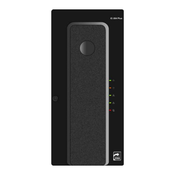
1.1.2 External LEDs and Controls This section identifies the external LEDs and controls of your IC-304 print controller. DVD-RW drive USB ports Power control button Power-on LED (green) Reset button Disk activity LED (orange) Not in use Network activity LED (green) Network activity LED (green) Not in use Front door open... - Page 20 Chapter 1—First Time Setup and Configuration 3. Wait 20 seconds before pressing the power control button on the IC-304 print controller (see Figure 2 on page 3). The ON/OFF LED on the front panel illuminates a steady green. After the system startup is complete, the Windows desktop appears. 4.
-
Page 21: Installing The Windows Xp Professional Operating System
Installing the Windows XP Professional Operating System After turning on the IC-304 print controller for the first time, the system automatically performs disk striping, and the following message appears. Click OK. The Configuration Wizard appears. Configuration Wizard (First-time Software Setup) The first-time software setup is performed using the Configuration Wizard. -
Page 22: Setting The Localization Parameters
Chapter 1—First Time Setup and Configuration 1.3.2 Setting the Localization Parameters You configure the measurement unit and language in the Localization window. In the Units area, select the required default measurement unit. 2. In the Language area, select the required interface language. 3. - Page 23 In the Server name area, verify that the correct host name appears and proceed to Configuring the Network Setup on page 9. If you need to change the host name, click the Change button. The System Properties dialog box appears.
- Page 24 Chapter 1—First Time Setup and Configuration 2. Click the Change button. Attention: Do not change the Workgroup or Domain in step 3 unless instructed to do so. If you are changing the Domain/Workgroup, verify that you have the user name and password for the Domain/Workgroup. 3.
-
Page 25: Configuring The Network Setup
1.3.4 Configuring the Network Setup You configure the IP address and AppleTalk® software zone in the Network Setup window. Configuring the IP Address In the TCP/IP Setup area, verify that the IP address is correct. If not, click the Change button. The Local Area Connection Properties dialog box, followed by the Internet Protocol (TCP/IP) Properties dialog box appears. - Page 26 Chapter 1—First Time Setup and Configuration 2. In Internet Protocol (TCP/IP) Properties dialog box, select Use the following IP Address. 3. In their corresponding boxes, type the new IP address, Subnet mask and Default gateway (if applicable). Note: After an operating system reinstall, by default, the IC-304 print controller is set to DHCP server configuration.
- Page 27 In the Apple Talk setup area, verify that the displayed AppleTalk software zone is correct and click Next. Otherwise, click the Change button. The Local Area Connection Properties dialog box appears, followed by the AppleTalk Protocol Properties dialog box. 2. Select the Accept inbound connections on this adapter check box. 3.
-
Page 28: Configuring The Connected Finishers
Chapter 1—First Time Setup and Configuration 1.3.5 Configuring the Connected Finishers You configure the finisher in the Connected Finishers window. Important: Select only the finisher attached to your printer. Selecting another finisher could result in incorrect finishing results. -
Page 29: Setting The Calibration Device
1.3.6 Setting the Calibration Device Select a calibration device setting and click Next. Calibration is done Off-the-glass—uses the scanner platen to measure the calibration charts Calibration is done using device tool—uses the spectrophotometer to measure the calibration charts... -
Page 30: Defining The Security Settings
Chapter 1—First Time Setup and Configuration 1.3.7 Defining the Security Settings Changing the Administrator and Operator Password (Optional) To change the administrator password: In the Passwords area, clear the Auto log on check box. 2. In the Enter new password box, type a new password. 3. -
Page 31: Completing The Configuration
1.3.8 Completing the Configuration After the installation is complete, the following window appears. Click Finish. The configuration settings are automatically backed up. After a few moments, the IC-304 print controller workspace appears on your screen. 2. Exit the IC-304 print controller software. If you made any changes to the configuration, these changes will only take effect if the IC-304 print controller is shut down and then restarted. -
Page 32: Configuring Mcafee Virusscan
Chapter 1—First Time Setup and Configuration After restarting, the IC-304 print controller software splash screen appears. 4. The IC-304 print controller software is automatically loaded and launched. You have completed First Time Setup and Configuration. Configuring McAfee VirusScan The current recommended virus protection software is McAfee VirusScan® software Enterprise version 8.0.0. -
Page 33: Configuring The Scan All Fixed Disks Settings
1.4.1 Configuring the Scan All Fixed Disks Settings From the taskbar, right-click the VShield icon and select VirusScan Console. 2. In the Task column, right-click Scan All Fixed Disks and select Properties. 3. Click the Detection tab. 4. In the What not to scan area, click Exclusions. - Page 34 Chapter 1—First Time Setup and Configuration 5. Click Add. 6. Click Browse. In the Browse for Folder window, locate the D:\Output folder and click OK. The D:\Output folder path appears. 8. Select the Also exclude subfolders check box and click OK. 9.
-
Page 35: Configuring The On-Access Scan Settings
1.4.2 Configuring the On-Access Scan Settings Return to the VirusScan Console window. 2. In the Task area, right-click On-Access Scanner and select Properties. 3. On the left of the window, click the All Processes icon. - Page 36 Chapter 1—First Time Setup and Configuration 4. Select the Detection tab. 5. In the What not to scan area, click Exclusions. 6. Click Add. Click Browse.
-
Page 37: Installing And Configuring Novell Client
8. In the Browse for Folder window, locate the D:\Output folder and click OK. 9. Select the Also exclude subfolders check box and click OK. 10. In the Set Exclusions dialog box, click OK. 11. In the VirusScan On-Access Scan Properties window, click OK. You have completed configuring the VirusScan software. - Page 38 Chapter 1—First Time Setup and Configuration 3. From the Windows Start menu, select IC-304PrintController > IC-304PrintController Tools > Novell Client Installation. 4. Click Install. 5. Click Reboot. 6. You have completed installing Novell Client™ software for the IC-304 print controller. Proceed to Configuring Novell Client for IC-304 Print Controller.
- Page 39 Configuring Novell Client for IC-304 Print Controller After the server restarts, the Novell Setup dialog box appears. 2. Type the Tree Name. 3. If you do not know the name, click Browse. 4. Double-click the appropriate Tree Name. The Tree Name appears in the Novell Setup window. 5.
- Page 40 Chapter 1—First Time Setup and Configuration 6. If you do not know the name, click Browse. Double-click the appropriate Context Name. The Context Name appears in the Novell Setup window. 8. Click OK. The IC-304 print controller work space appears. 9.
-
Page 41: Performing A Test Print
5. Make sure the Novell Client for Windows check box is selected, and then click the Uninstall button. 6. Click Yes twice. The IC-304 print controller restarts. You have completed uninstalling Novel Client software for the IC-304 print controller. Performing a Test Print To import a file and perform a test print: From the File menu select Import. - Page 42 Chapter 1—First Time Setup and Configuration To back up your system: Exit the IC-304 print controller work space. 2. Insert DVD #1 (Fast Install SLP) into the DVD-RW drive. 3. From the Windows Start menu, select Shut Down > Restart > OK. After the system restarts, the IC-304 print controller Startup Menu appears.
- Page 43 7. To back up the entire system (partitions C and D), press 3. This option backs up partitions C and D. You may need more than one DVD for the backup. a. Press Y to continue. b. To continue, press Y. c.
-
Page 44: Setting Up The Disk Wipe Utility
Chapter 1—First Time Setup and Configuration Setting Up the Disk Wipe Utility Note: The Disk Wipe utility runs automatically only after you shut down the IC-304 print controller. The Disk Wipe utility is recommended for high security customers. Usually when you delete a file, the file’s dictionary entry is removed but data still remains on the disk. -
Page 45: Reinstalling The Ic-304 Print Controller Software
Reinstalling the IC-304 Print Controller Software Overview........................30 Backing Up and Restoring the Software ............31 Reinstalling the System..................38 Reinstalling the Software—Complete Overwrite .......... 39 Reinstalling the Software—Preservation Installation........58... -
Page 46: Overview
Chapter 2—Reinstalling the IC-304 Print Controller Software Overview This chapter describes when and how to: • Back up and restore the IC-304 print controller operating system, including the current job list database, on your computer • Reinstall the software configuration on your IC-304 print controller 2.1.1 When to Back Up and Restore Back up the IC-304 print controller system on a regular basis—for example,... -
Page 47: Pre-Loaded Software
2.1.3 Pre-loaded Software The IC-304 print controller is delivered to the customer site preloaded with the following software: • Windows XP operating system with Microsoft Service Pack 2 • Nero • Microsoft Internet Explorer 6 • IC-304 print controller software •... - Page 48 Chapter 2—Reinstalling the IC-304 Print Controller Software 2. Back up the job list database. Note: For instructions, see Backing Up the Job List Database on page 33. 3. Move the backups to an external device or to a network. 4. Restore the system partition. Note: For instructions, see Restoring the IC-304 Print Controller System Partition on page 34.
-
Page 49: Backing Up The Job List Database
2.2.1 Backing Up the Job List Database If you back up the IC-304 print controller software and configuration, your job list database is also backed up. If, at some later date, you restore the configuration, the original job list database will be restored, thus replacing your current job list database. -
Page 50: Restoring The Ic-304 Print Controller System Partition
Chapter 2—Reinstalling the IC-304 Print Controller Software 6. Press any key to continue. You have completed backing up the job list database. 2.2.2 Restoring the IC-304 Print Controller System Partition Note: Before performing the restore procedure, if the job list database was not backed up or cannot be restored, you must format the image disks. - Page 51 5. Press Y to confirm your selection. Note: Before restoring the color server system partition, you may need to return the ghost file or files that you moved to an external device to D:\Backup 6. To restore only partition C, press 2. This option restores partition C from the image file on partition D.
- Page 52 Chapter 2—Reinstalling the IC-304 Print Controller Software To restore partitions C and D, press 4. This option restores partitions C and D from a backup media. a. Press Y to continue. b. Press Y to continue. c. Follow the instructions in the message. d.
-
Page 53: Restoring The Job List Database
2.2.3 Restoring the Job List Database When you restore the IC-304 print controller software and configuration that you previously backed up, you are replacing the current job list database with your original job list database. Exit the IC-304 print controller work space. 2. -
Page 54: Reinstalling The System
Chapter 2—Reinstalling the IC-304 Print Controller Software 2.3 Reinstalling the System There are two methods by which you can reinstall the system: • Color Server Software Complete Overwrite Installation: This procedure replaces the entire system disk, operating system partition, IC- 304 print controller software, and user partition (partitions C and D). -
Page 55: Reinstalling The Software-Complete Overwrite
2.4 Reinstalling the Software—Complete Overwrite Note: When possible, we recommend that you back up and restore the software. That is, in cases other than system crash or system disk replacement. For more information, see Backing Up and Restoring the Software on page 31. The following workflow enables you to establish which procedure to perform and in what sequence. -
Page 56: Reinstalling The Operating System (Windows Xp)
Chapter 2—Reinstalling the IC-304 Print Controller Software 2.4.1 Reinstalling the Operating System (Windows XP) Before reinstalling, ensure that: • All external devices are disconnected from the IC-304 print controller • The following is available: Software pack (DVD #1, DVD #2) Note: DVD #1, which includes the operating system, does not require entering a license number or activation. -
Page 57: Reinstalling The Color Server Software
5. The system starts copying the files. This process takes about eight minutes, and then the following message appears: Please remove any media from the DVD-RW drive and press Ctrl+Alt+Del to reboot the computer. 6. Remove DVD #1 from the DVD-RW drive, and press CTRL DELETE restart. -
Page 58: Disk Striping
Chapter 2—Reinstalling the IC-304 Print Controller Software 2.4.3 Disk Striping After the IC-304 print controller restarts, the Wrong Disk Configuration message may appear. This message indicates that the disks need to be striped. Establishing the Correct Disk Striping Procedure Note: If the Image Disks File System is not Formatted message appears, proceed to step 2 of the Confirming the Disk Striping procedure on page 53. - Page 59 To establish the correct disk striping procedure: If the following message appears, click OK. The Computer Management window appears. 2. Do one of the following actions: • Stripe the foreign disks— See Striping Foreign Disks. • Stripe the unknown disks—See Striping Unknown Disks on page 45. •...
- Page 60 Chapter 2—Reinstalling the IC-304 Print Controller Software Striping Foreign Disks Perform the following procedure to remind the operating system that a striped volume resides within the operating system. In the Computer Management window, verify that Disks 1 and 2 are labeled Dynamic.
- Page 61 3. Verify that the Foreign disk set (2 of 2 disks selected) check box is selected and click OK. 4. Click OK. The Dynamic disks are striped, as shown in the following window. 5. Close the Computer Management window. 6. When the message Image Disks File System is not Formatted appears, click OK.
- Page 62 Chapter 2—Reinstalling the IC-304 Print Controller Software To initialize the disks: In the Disk Management widow, right-click the Disk 1 area, and select Initialize Disk. 2. Verify that both image disk check boxes are selected, and click OK. 3. Verify that the Computer Management window appears similar to the following window.
- Page 63 2. Select Convert to Dynamic Disk. 3. Select the Disk 0 and 1 check boxes and click OK. Attention: Do not select the Disk check box. Disk is the system disk and selecting the Disk check box will cause all information to be lost. 4.
- Page 64 Chapter 2—Reinstalling the IC-304 Print Controller Software Removing a Missing Disk Perform the following procedure when you have replaced a faulty disk and the system remembers that the disk that was replaced is missing. Right-click the white area opposite the missing disk. 2.
- Page 65 The missing disk volume is deleted, as shown in the following window: 4. Right-click the Missing Dynamic area.
- Page 66 Chapter 2—Reinstalling the IC-304 Print Controller Software 5. Select Remove Disk. The missing disk is deleted, as shown in the following window: 6. Create a striped volume. See Creating a Striped Volume. Creating a Striped Volume After you have replaced a disk, or low-level formatted one or more disks, you need to create a striped volume.
- Page 67 2. Click Next. 3. Select Striped and click Next. 4. In the Available area, select each disk that you want to include in the new volume and click Add.
- Page 68 Chapter 2—Reinstalling the IC-304 Print Controller Software 5. Click Next. 6. Select Do not assign a drive letter or drive path and click Next. Select Do not format this volume, and click Next. 8. Click Finish. 9. Confirm that the disks are striped. See Confirming the Disk Striping on page 53.
-
Page 69: Using The Configuration Wizard
Confirming the Disk Striping After you complete the New Volume Wizard, the Computer Management window appears: Close the Computer Management window. 2. When the message Image Disks File System is not Formatted appears, click OK. The Configuration Wizard appears. Note: If a message appears requesting you to activate Windows XP operating system, ignore it until you have completed configuring the system. - Page 70 Chapter 2—Reinstalling the IC-304 Print Controller Software Follow the steps in the wizard to complete the relevant configuration. Note: During the configuring process, when prompted to restart your computer, click Configuring the IC-304 Print Controller for the First Time To configure the IC-304 print controller for the first time, see Configuration Wizard (First-time Software Setup) on page 5.
- Page 71 Select DFE Configuration recovery, and click Next. 2. If you would like to restore the default configuration, select Default Configuration. 3. If you received the message , or if you Error in default configuration want to use a different configuration file than the default, choose Select Configuration and click Browse.
-
Page 72: Configuring The Mcafee Virusscan
Chapter 2—Reinstalling the IC-304 Print Controller Software In the Step 2 Recovery window, click Next. 8. Click Finish. The IC-304 print controller workspace appears on your screen. Note: For your changes to take effect, you must restart the server. 9. To make sure that changes take effect, close all open software and, from the Windows Start menu, select Shut Down >... -
Page 73: Backing Up The Color Server System Partition
2.4.8 Backing Up the Color Server System Partition To back up the ColorServer system partition, see Backing up the IC-304 Print Controller System on page 25. -
Page 74: Reinstalling The Software-Preservation Installation
Chapter 2—Reinstalling the IC-304 Print Controller Software 2.5 Reinstalling the Software—Preservation Installation Note: To enable the restoration of customer settings and job data, we recommend that you back up the IC-304 print controller configuration and other information before loading the operating system, see Backing Up the Color Server System Partition on page 57 and Backing Up the Job List Database on page 33. -
Page 75: Diagnostics And Troubleshooting
Diagnostics and Troubleshooting Platform Diagnostics and Configuring the Server.........60 General Diagnostic Tools..................70 IC-304 Print Controller Hardware Diagnostics Software ......72 Troubleshooting ..................... 78... -
Page 76: Platform Diagnostics And Configuring The Server
Chapter 3—Diagnostics and Troubleshooting Platform Diagnostics and Configuring the Server This section provides basic troubleshooting information to help you resolve some issues that might possibly occur with the IC-304 print controller. To maintain the good health of the server, it is important that the server continuously remains correctly configured. - Page 77 Troubleshooting the Ethernet Controller This section provides troubleshooting information for problems that might occur with the 10/100/1000-Mbps Ethernet controller. To resolve network connection problems: If the Ethernet controller cannot connect to the network, perform the following: • Check the BIOS configuration relating to the LAN. •...
-
Page 78: Using The Configuring Tools
Chapter 3—Diagnostics and Troubleshooting 4. Roll the cursor over the network icon in the taskbar to display the speed, as shown in the following example: 3.1.2 Using the Configuring Tools Using the Phoenix cME FirstBIOS Pro Setup Utility This section provides instructions for starting the Phoenix cME FirstBIOS Pro Setup Utility and descriptions of the menu choices available for configuring the BIOS. - Page 79 The Phoenix cME FirstBIOS Pro Setup Utility Main menu is similar to the following: Note: The choices on some menus might differ slightly from the ones that are described in this manual. The menu choices depend on the BIOS version in the server.
-
Page 80: Advanced Menu
Chapter 3—Diagnostics and Troubleshooting Selecting From the Phoenix cME FirstBIOS Pro Setup Utility Advanced Menu Boot Features—Select this submenu to change the following settings: Quick Boot Mode: If enabled, this feature will speed up the POST (power-on self test) routine after the computer is turned on. - Page 81 Floppy Disk Controller: This setting allows you to assign control of the floppy disk controller. • Hardware Monitor: Select this submenu to change the following settings: CPU Temperature Threshold: This option allows you to set a CPU temperature threshold that will activate the alarm system when the CPU temperature reaches the predefined temperature threshold.
- Page 82 Chapter 3—Diagnostics and Troubleshooting 2. If required, change the System Time and System Date and verify that the rest of the settings are the same as the settings in the following window. a. Press to save any changes. ENTER 3. Using the arrow keys, select the Advanced menu. 4.
- Page 83 5. Verify that the settings are the same as the settings in the following window. 6. Press to return to the Advanced menu. 7. Using the arrow keys, select Advanced Processor Options and press ENTER 8. Verify that the settings are the same as the settings in the following window: 9.
- Page 84 Chapter 3—Diagnostics and Troubleshooting 11. Verify that the settings are the same as the settings in the following window. 12. Press to return to the Advanced menu. 13. Using the arrow keys, select Hardware Monitor and press ENTER 14. Verify that the settings are the same as the settings shown in the window in following window.
- Page 85 16. Select the Boot menu and verify that the settings are the same as shown in the following window: Phoenix cME TrustedCore Pro Setup Utility Main Advanced Security Boot Exit Item Specific Help Boot priority order: 1: USB LS120: Keys used to view or 2: USB KEY: configure devices: 3: IDE CD:...
-
Page 86: General Diagnostic Tools
Chapter 3—Diagnostics and Troubleshooting 20. To view the BIOS setup utility Setup Utility summary window in detail, when the system starts or restarts and the window appears, immediately press PAUSE on your keyboard. BREAK 21. Press any key to continue. You have completed Configuring the Computer BIOS. -
Page 87: Post (Power On Self Test)
Hardware BIOS Virus Protection The system BIOS is protected by hardware so that no virus can infect the BIOS area. This feature can prevent viruses from infecting the BIOS area and destroying valuable data. Auto-Switching Voltage Regulator for the CPU Core The 3-phase-switching voltage regulator for the CPU core can support up to 60 A current and auto-sense voltage IDs ranging from 1.1 V to 1.85 V. -
Page 88: Print Controller Hardware Diagnostics Software
Chapter 3—Diagnostics and Troubleshooting Code Beep POST Routine Description Recovery Action • 2-2-3-1 Test for unexpected interrupts Remove and reseat the PCI adapters, one at a time, check if faulty, and replace the faulty adapter. • Reload a different BIOS. •... -
Page 89: Activating The Diagnostics Software
3.3.1 Activating the Diagnostics Software Notes: Only run the Diagnostics utility after you exit the IC-304 print controller software. Wait for the IC-304 print controller software taskbar icon to disappear before continuing. Quitting the IC-304 Print Controller Software In the IC-304 print controller workspace, click the File menu and select Exit. 2. -
Page 90: Main Menu Options
Chapter 3—Diagnostics and Troubleshooting The DFE User Diagnostics window is divided into four sections: • The top section contains the Main Menu bar with five different menu options: File, View, Control, Level, and Help. • The next section under the Main Menu bar contains shortcut buttons for performing the main JOIND operations. -
Page 91: Help Menu
Control Menu Initiates a test session, after the items for testing in this session are marked in the check boxes. When Loop Off is selected, the test session terminates after each test has been executed. When Loop On is selected, the loop sequence is toggled on and the test session repeats until the loop termination condition is reached. -
Page 92: Shortcut Buttons
Chapter 3—Diagnostics and Troubleshooting Shortcut Buttons The shortcut buttons are found beneath the main menu bar and are available for performing the main operations when running diagnostics tests. Initiates the Run command to perform a diagnostic test running in loop or executing batch of tests. Terminates a test running in loop or executing batch of tests. -
Page 93: Board Diagnostics
3.3.4 Board Diagnostics This section describes the diagnostics for the IC-304 print controller boards. The board included in this category is FusionIN. Use the JOIND diagnostic utility to test the IC-304 print controller boards. If a board fails a test, first verify that it is properly connected (turn off the IC-304 print controller and check the board connections including cables and pins;... -
Page 94: Troubleshooting
Chapter 3—Diagnostics and Troubleshooting Diagnostics Test Results This section lists the possible results of the diagnostics test and the recovery actions. Symptom Recovery Action The FusionIN 1. Verify that the FusionIN board is correctly seated. board fails the 2. Verify that the memory tests passed. If one or both test. -
Page 95: Print Controller Does Not Turn On
3.4.1 IC-304 Print Controller Does Not Turn On Symptom Recovery Action IC-304 print Verify that: controller • The power cables are properly connected to the IC- does not turn 304 print controller • The electrical outlet functions properly • The power-on LED is illuminated •... -
Page 96: Print Controller Turns On, No Operating System
Chapter 3—Diagnostics and Troubleshooting 3.4.2 IC-304 Print Controller Turns On, No Operating System In this situation it is not possible to run the JOIND diagnostics software. Symptom Recovery Action The operating Verify the following: system does • The SATA2 cables and the power cables are not initialize. -
Page 97: Memory Problems
3.4.4 Memory Problems Symptom Recovery Action The amount of Verify that: memory displayed 1. The memory modules are seated properly. is less than the 2. You installed the correct type of memory (ECC amount of DDR2 memory, part number memory installed. Creo 102-00105). -
Page 98: Common Problems
Chapter 3—Diagnostics and Troubleshooting 3.4.6 Common Problems Symptom Recovery Action During installing the 1. Restart the computer. operating system, 2. If you just installed an option, remove it and you see a blue restart the IC-304 print controller. screen. An image disk is not Check the following: identified. - Page 99 Symptoms and Troubleshooting Symptom Recovery Action Further Action (if printing fails) If printing fails, refer to General 1. Shut down your printer and the IC-304 print the next symptom. controller. 2. Check that the FusionIN printer cable is securely connected to the IC-304 print controller port. 3.
-
Page 100: General Power Checkout
Chapter 3—Diagnostics and Troubleshooting 3.4.8 General Power Checkout Power problems can be difficult to troubleshoot. For instance, a short circuit can exist anywhere on any of the power distribution buses. Usually a short circuit causes the power subsystem to shut down because of an over-current condition. A general procedure for troubleshooting power problems is as follows: Turn off the system and disconnect the AC power cord(s). - Page 101 System Error Messages Message Recovery Action System error. Reboot the 1. Restart the system from the system. Start menu. 2. If the error message reappears, run the diagnostics test. Reinstall the IC-304 print System error. Reinstall controller software, and restart the the IC-304 print system.
-
Page 102: Collecting Data Log Files
Chapter 3—Diagnostics and Troubleshooting Connection Error Messages Message Recovery Action Ethernet 1. Check the cable connections. connection 2. Restart the client workstation computer failure and the IC-304 print controller. 3. Check the communication parameters in the client workstation computer and the IC-304 print controller. -
Page 103: Formatting The Image Disk
3. Restart the IC-304 print controller software. 4. Recreate the problem you have encountered and then click the STOP button. The IC-304 print controller software closes automatically and the log files are saved as a Data_logs.cab file in D:\ Shared, or in the location previously specified in step 2. - Page 104 Chapter 3—Diagnostics and Troubleshooting 5. Click Yes. 6. Click OK. To enable the changes to take effect, restart your computer.
-
Page 105: Hardware And Maintenance Repairs
Hardware and Maintenance Repairs System Components ....................90 Spare Parts List......................91 Before You Begin....................92 Removing and Replacing the Side Cover and Front Panel......93 Working with Boards (Adapters) ..............97 Working With the System Board..............103 Removing and Installing the DVD-RW Drive ..........118 Removing and Installing a Hard Disk Drive ........... -
Page 106: System Components
Chapter 4—Hardware and Maintenance Repairs System Components Use the following diagram to locate a specific part for replacement. In the Spare Parts List on page 91, each number in the Item number column corresponds to a spare part—not all the parts in the spare parts list are illustrated. Figure 1: Spare parts diagram... -
Page 107: Spare Parts List
4.2 Spare Parts List IC-304 Print Controller Spare Parts List (FRUs- Field Replaceable Units) Item Description Creo Part Type Qty/ Number Number Unit Processor, Intel Core2 104-00066 CPU processor Duo, E8400, 3.0 GHz, 6 MB cache, 1333 MHz DDR SDRAM, 256 MB, 120-00105 Output memory SODIMM200,... -
Page 108: Before You Begin
Chapter 4—Hardware and Maintenance Repairs IC-304 Print Controller Spare Parts List (FRUs- Field Replaceable Units) Item Description Creo Part Type Qty/ Number Number Unit Fan, 12 V (92 x 92 mm) 220-01391A Third party Fan, computer rear 609-00393 Third party (120 x 120 mm) Fan, CPU CORE2 DUO 609-00426... -
Page 109: Removing And Replacing The Side Cover And Front Panel
Some of the benefits of moving from Parallel ATA to Serial ATA technology are: • Improved performance—Serial ATA is faster than Parallel ATA • Simpler configuration—jumpers and settings eliminated • Reduces voltage and pin count • Smaller easier-to-route cables—eliminate the cable-length limitation and allow better airflow •... -
Page 110: Returning The Side Cover
Chapter 4—Hardware and Maintenance Repairs 5. Move the side cover outward and away from the server. Pull handle to release cover, Remove the two screws and slide out of chassis Figure 2: Removing the side cover 4.4.2 Returning the Side Cover Verify that the server is off and that all external cables are disconnected. - Page 111 3. Remove the side cover (see Removing the Side Cover on page 93). Tip: It is easier to perform this procedure if you place the server on its side on a table, with the front panel of the tower computer case protruding over the table edge.
-
Page 112: Returning The Front Panel
Chapter 4—Hardware and Maintenance Repairs 6. When the front panel is free, pull it away from the front of the chassis, and then push it downward to release the concealed tabs along the bottom of the front panel from the chassis. Concealed tabs Protruding tabs Figure 4: Front panel removed showing protruding and concealed tabs... -
Page 113: Working With Boards (Adapters)
4.5 Working with Boards (Adapters) If the diagnostics check (see Chapter 3, Diagnostics and Troubleshooting) indicates that any unit components need replacing, follow the replacement procedures. The following diagram illustrates schematically the external connectivity of the peripherals and the internal connectivity of the main components of the IC-304 print controller. -
Page 114: Removing And Installing The Fusionin Board And Memory Modules
Chapter 4—Hardware and Maintenance Repairs 4.5.2 Removing and Installing the FusionIN Board and Memory Modules The FusionIN board simultaneously decompresses and RIPs data for the duration of a job. Perform the following procedures to remove and install the FusionIN board and memory modules. - Page 115 6. Continue to lift the board and remove it from the computer. IN_MEM OUT_MEM OUT_MEM Figure 7: FusionIN board and memory modules Removing Memory Modules Place the board, component-side up, on a flat, antistatic surface. 2. Remove the memory modules from the board positions: IN_MEM, OUT_MEM. a.
- Page 116 Chapter 4—Hardware and Maintenance Repairs 3. Push the memory module gently downward until the locking clips click into position. See Figure 7 on page 99. Locking clip seat. Figure 8: Memory module and locking clip seat Note: When replacing FusionIN board memory modules, verify that you are using the same memory size and type.
-
Page 117: Removing And Installing System Board Memory Modules
4.5.3 Removing and Installing System Board Memory Modules Your IC-304 print controller comes withDual In-line Memory Modules (DIMMs) that are installed on the system board in DIMM bank #1A (blue) and DIMM bank #2A (blue). Note: Removing or installing DIMMs may change the configuration information in the server. - Page 118 Chapter 4—Hardware and Maintenance Repairs Installing a DIMM Touch the antistatic package containing the new DIMM to any unpainted metal surface on the server, and then remove the DIMM from the package. 2. Verify that the DIMM release tabs are open. 3.
-
Page 119: Working With The System Board
4.6 Working With the System Board This section shows illustrations of the components on the system board, and procedures for removing and installing the system board. Note: It is recommended to perform all the procedures in this section with the server on its bottom on a table. -
Page 120: System Board External-Port Connectors
Chapter 4—Hardware and Maintenance Repairs 4.6.2 System Board External-Port Connectors The following illustration identifies system board connectors for external devices. Not in LAN 1 Figure 12: System board external port connectors LAN2 (Not in use) LAN1 (client network) VGA port (monitor) COM1 port (DTP) USB ports 1/2 (mouse) Keyboard... -
Page 121: Installing A New System Board
9. Lift the system board up and out of the server. 10. Turn over the system board and remove the metal bracket from the board. Set aside the bracket to install on the new system board. 4.6.4 Installing a New System Board Attention: When you handle electrostatic discharge (ESD) sensitive devices, take precautions to avoid damage from static electricity. - Page 122 Chapter 4—Hardware and Maintenance Repairs Adhesive tape Figure 13: Metal bracket a. Turn over the bracket so that it is face down and align it with the diagram on the system board. Figure 14: Diagram of metal bracket b. When the bracket is properly aligned (the four ends should fit into place over the holes), gently press the bracket into place.
- Page 123 Note: If you are reusing a metal bracket that was attached to a previous system board, the glue may have weakened and lost some of its adhesiveness. Therefore, make sure to support the bracket with one hand when installing the system board to its upright position, 6.
- Page 124 Chapter 4—Hardware and Maintenance Repairs 15. Reconnect all the cables that you disconnected from the system board, power supply unit and hard disks. Note: To assist you in reconnecting the cables to the system board. See the following table and Figure 11 on page 103. Table 1: System Board Cable Connections Cable System Board Connector...
-
Page 125: Removing And Installing The Central Processing Unit (Cpu)
4.6.5 Removing and Installing the Central Processing Unit (CPU) Note: he microprocessor speeds are automatically set for this server so you do not need to set any microprocessor frequency-selection jumpers or switches. Preparing to Remove the CPU Attention: When you handle static-sensitive devices, take precautions to avoid damage from static electricity. - Page 126 Chapter 4—Hardware and Maintenance Repairs 2. Release the four spring screws that secure the CPU fan and heat sink assembly to the system board. Important: Loosen the screws using the crisscross method. First loosen screws 1 and 2, and then screws 3 and 4. Once all four screws are loose, remove them diagonally, one after the other, in the order previously described, until all four spring screws have been removed.
- Page 127 2. Using your thumb and index finger, carefully grasp the microprocessor by its north and south center edges and lift it up and out of the server. North center edge South center edge Figure 22: Removing the microprocessor 3. Store the microprocessor in an antistatic package for possible future use.
- Page 128 Chapter 4—Hardware and Maintenance Repairs Installing the Microprocessor Touch the antistatic package containing the new microprocessor to any unpainted metal surface on the server, and then remove the microprocessor from the package. 2. Unlock the microprocessor socket. a. Press the socket lever down to release the load plate from its locking position.
- Page 129 Pin 1 Figure 25: Locating pin 1 on the microprocessor socket a. Make sure that Pin 1 of the microprocessor socket is located at the left bottom of the microprocessor housing. 4. Insert the microprocessor into the microprocessor socket. North center edge South center edge Figure 26: Aligning the microprocessor...
- Page 130 Chapter 4—Hardware and Maintenance Repairs a. Using your thumb and index finger, hold the microprocessor by its north and south center edges and align Pin 1 of the microprocessor with Pin 1 of the microprocessor socket. b. When aligned, carefully lower the microprocessor straight down to the socket.
- Page 131 2. Position the CPU fan and heat sink assembly in such a way that the fan wires are close to the microprocessor fan, but do not obstruct other components. 3. Apply thermal grease to the top of the microprocessor. Thermal grease Figure 29: Applying thermal grease 4.
-
Page 132: Removing And Installing The Battery
Chapter 4—Hardware and Maintenance Repairs Figure 30: Securing the CPU fan and heat sink assembly 5. Connect the CPU fan cable to the CPU Fan 6 connector. See Figure 19 on page 109. 6. If you have other options to install or remove, do so now. Return the FusionIN board. -
Page 133: Installing The Battery
3. Remove the side cover. See Removing the Side Cover on page 93. 4. Remove the FusionIN board to gain access to the battery. 5. Remove the battery: a. Use one fingernail to press the top of the battery clip away from the battery. The battery pops up when released. -
Page 134: Removing And Installing The Dvd-Rw Drive
Chapter 4—Hardware and Maintenance Repairs 4.7 Removing and Installing the DVD-RW Drive Perform the following procedures to remove and install the DVD-RW drive. Retaining tab (on each side) Figure 33: Bay1 DVD-RW drive 4.7.1 Removing the DVD-RW Drive Review Safety Information (Multi-Language) on page ix. 2. -
Page 135: Installing The Dvd-Rw Drive
4.7.2 Installing the DVD-RW Drive Install the tab strips to the new DVD-RW drive that you removed from the old DVD-RW drive. See Figure 34. 2. Slide the DVD-RW drive into the DVD-RW drive cage, making sure that the drive locks into place. 3. -
Page 136: Installing A Hard Disk
Chapter 4—Hardware and Maintenance Repairs 5. Lift the drive cage up and out of the server. Figure 35: Removing a hard disk drive 6. Identify which hard disk you want to remove. Loosen the two screws on either side of the disk drive and pull the disk drive out of the chassis. -
Page 137: Removing And Installing The Power Supply
6. Connect the SATA2 cables into the back of each drive. Make sure that the other end of each cable is connectedto the appropriate connector on the system board. DVD R/W System disk Image disks Figure 36: SATA2 connectors on the system board 7. -
Page 138: Installing The Power Supply
Chapter 4—Hardware and Maintenance Repairs Gently move the power supply out of the server. Screws Figure 37: Removing the power supply unit 4.9.2 Installing the Power Supply Orient the power supply and insert it into the server. 2. Insert the power supply into the opening at the rear of the chassis. 3. -
Page 139: Removing And Installing The Rear Fan
4.10 Removing and Installing the Rear Fan Perform the following procedures to remove and install the rear fan. Connector Fan5 (Rear fan) Connector Fan4 (Front fan) Figure 38: Rear and front fan connector locations 4.10.1 Removing the Rear Fan Review Safety Information (Multi-Language) on page ix. 2. -
Page 140: Installing The Rear Fan
Chapter 4—Hardware and Maintenance Repairs Remove the four screws that secure the fan to the rear-fan bracket. See Figure 39 on page 124. Figure 39: Rear fan 4.10.2 Installing the Rear Fan Align the four holes in the new fan with the matching holes in the rear-fan bracket, then insert the four screws and tighten. -
Page 141: A Specifications And Standards
Specifications and Standards Environmental Requirements ................126 Installation Steps ....................126 Specifications ....................... 126 Operating Environment..................127 Standards....................... 128 Reliability and Maintenance ................129... -
Page 142: Environmental Requirements
Chapter A—Specifications and Standards Environmental Requirements This chapter lists the software installation steps, includes specifications for the IC- 304 print controller operating environment, and provides a list of the international safety standards to which the IC-304 print controller conforms. A.2 Installation Steps •... -
Page 143: Operating Environment
Keyboard D x W x H (mm) D x W x H (in.) Weight Unpacked 470×150×40 18.5×5.9×1.57 2.0 kg/4.4 lb. Packed 450×140×30 17.7×5.5×1.18 1.0 kg/2.2 lb. Stand D x W x H (mm) D x W x H (in.) Weight (Contents and Carton) [Optional]... -
Page 144: Standards
Chapter A—Specifications and Standards Relative humidity Operating 5% to 85% Storage Max 95% @ 50° C (122° F) Items complying with IEC 721-3-0,1, 2, 3 Vibration Shipping Acceleration spectral density of 1m in frequency range of 10–200 Hz and acceleration spectral density of 0.3 m /sec in frequency range of... -
Page 145: Emc Requirements
Germany Portugal Greece Russian Federation A.5.2 EMC Requirements United States FCC 47CFR part 15: 2005, subpart B class B Canada ICES-003: 2004 issue 4, class B Japan VCCI V-3/2005.04, class B Australia and New Zealand CISPR 22: 2004, class B Europe EMC Directive 89/336/EEC European EMC standards... -
Page 146: General Maintenance Information
Chapter A—Specifications and Standards IC, DDR SDRAM, 512 MB, 2.7 GB/S, 4,591,368 200P-SODIMM, LF FusionIN board assembly 148,685 DVD-RW drive 90,909 Monitor TFT, LCD 17 in. 54,548 Hard disk drive, SATA2, 80 GB, 1,091,346 7200 RPM Memory, 512 MB, DDR2 ECC 4,591,368 Keyboard and Mouse, basic 54,546... - Page 148 Creo Color Servers...
Need help?
Do you have a question about the IC-304 Plus and is the answer not in the manual?
Questions and answers