Table of Contents
Advertisement
Quick Links
Operating Instructions and Parts Manual
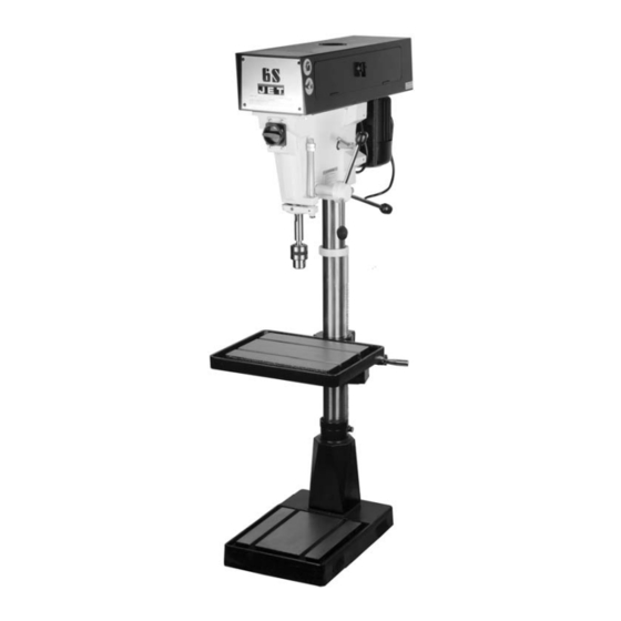
15-Inch Vari-Speed Drill Press
Models: J-A3816, J-A5816, J- A5818
Model J-A3816
Model J-A5816
WMH TOOL GROUP, Inc.
427 New Sanford Road
LaVergne, Tennessee 30786
Part No. M-354500
Ph.: 800-274-6848
Revision A2 03/09
www.wmhtoolgroup.com
Copyright © 2009 WMH Tool Group
Advertisement
Table of Contents

Subscribe to Our Youtube Channel
Related Manuals for Jet J-A3816


Summary of Contents for Jet J-A3816
- Page 1 Operating Instructions and Parts Manual 15-Inch Vari-Speed Drill Press Models: J-A3816, J-A5816, J- A5818 Model J-A3816 Model J-A5816 WMH TOOL GROUP, Inc. 427 New Sanford Road LaVergne, Tennessee 30786 Part No. M-354500 Ph.: 800-274-6848 Revision A2 03/09 www.wmhtoolgroup.com Copyright © 2009 WMH Tool Group...
-
Page 2: Warranty And Service
Service Centers located throughout the United States can give you quick service. In most cases, any of these WMH Tool Group Authorized Service Centers can authorize warranty repair, assist you in obtaining parts, or perform routine maintenance and major repair on your JET® tools. For the name of an Authorized Service Center in your area call 1-800-274-6848. MORE INFORMATION WMH Tool Group is consistently adding new products to the line. -
Page 3: Table Of Contents
Parts List - Head Model J-A3816 ......................... 18 Exploded View — Head Model J-A3816......................20 Parts List – Base Floor Models J-A3816, J-A5816 and J-A5818 ................ 21 Exploded View – Base Floor Models J-A3816, J-A5816 and J-A5818..............22 The specifications in this manual are given as general information and are not binding. WMH Tool Group reserves the right to effect, at any time and without prior notice, changes or alterations to parts, fittings, and accessory equipment deemed necessary for any reason whatsoever. -
Page 4: Warnings
Warnings 1. Read and understand the entire owner's manual before attempting assembly or operation. 2. Read and understand warnings posted on the machine and in this manual. Failure to comply with all of these warnings may cause serious injury. 3. Replace warning labels if they become obscured or removed. 4. - Page 5 24. Check for damaged parts. Before further use of the tool, a guard or other part that is damaged should be carefully checked to determine that it will operate properly and perform its intended function - check for alignment of moving parts, binding of moving parts, breakage of parts, mounting, and any other conditions that may affect its operation.
-
Page 6: Safety Instructions For Drill Presses
Safety Instructions for Drill Presses 1. All work shall be secured using either clamps or 6. Always wear protective wear when a vise to the drill press table. It is unsafe to use operating, servicing or adjusting machinery. your hands to hold any workpiece being drilled. Eyewear shall be impact resistant, protective safety glasses with side shields complying with 2. -
Page 7: Specifications
LED speed display on the faceplate of the machine. JET's 15-inch vari-speed drill press provides a solid base for drilling and offers a wide range of spindle speeds. The large quill provides greater accuracy. -
Page 8: Introduction
Set-up This manual includes operating and maintenance Securing the Base instructions for the JET 15-Inch Vari-Speed Drill Presses, Models J-A3816, J-A5816, and J-A5818. The base of the drill press has four mounting holes. This manual also includes parts listings and The drill press should be level and rest solidly on the illustrations of replaceable parts. -
Page 9: Depth Stop
1. The head assembly must be locked to the column so the thrust produced by drilling will not force the head assembly up the column. LED Speed 2. The work table must be locked to the column so Display it will not be forced down the column. 3. -
Page 10: Maintenance
Indication of Extreme Speeds and Feeds 3. Remove head cover. A drill that splits up the web is evidence of too much 4. Remove belt. (With speed control setting at the feed or insufficient tip clearance at the center as a highest speed, the belt should be loose enough result of improper grinding. -
Page 11: Adjustments
Adjustments Table Adjustment The table can be raised or lowered to accommodate the height of the component being drilled (refer to Figure 4). To raise or lower the table, loosen the lock handle. Then use the hand crank to move the table to the desired height. -
Page 12: Electrical
As received from the factory, your drill press is ready to run at 115-volt operation. This drill press, when 2. The JET drill press motor has four numbered wired for 115 volt, is intended for use on a circuit leads that are factory connected for 115V that has an outlet and a plug that looks like the one operation, as shown in (A). -
Page 13: Grounding Instructions
Grounding Instructions The drill press with a 230-volt plug should only be connected outlet having same configuration (D, Fig. 7). No adapter is available or This tool must be grounded should be used with the 230-volt plug. while in use to protect the operator from electric shock. -
Page 14: Troubleshooting
Troubleshooting Problem Probable Cause Suggested Remedy Spindle does Circuit breaker tripped. Reset circuit breaker. not turn. Branch circuit breaker tripped or fuse Reset branch circuit breaker/replace fuse. blown. Open wire in switch circuit. Repair open circuit. Defective switch. Repair switch. belt. -
Page 15: Parts List - Head Models J-A5816 And J-A5818
Parts List - Head Models J-A5816 and J-A5818 Item Part No. Description Size Qty. 1 ....5507580 ....Chuck (with Key)..................1 2A .....5507495 ....Arbor ..............#2 MT x JT3....1 3A .....5507496A....Spindle ..................... 1 4 ....J-5053070 ....Quill Band....................1 5 ....9010541 ....O-Ring.............. - Page 16 Parts List - Head Models J-A5816 and J-A5818 Item Part No. Description Size Qty. 55 .....5041140 ....Vaiable Speed Pulley (Spindle) ............... 1 55A ...5513510 ....Hex Nut ....................1 55B ...5513511 ....SHCS ...................... 1 56 .....9100421 ....Bearing..................... 1 57 .....9058571 ....Spring Washer ............
-
Page 17: Exploded View - Head Models J-A5816 And J-A5818
Exploded View — Head Models J-A5816 and J-A5818... -
Page 18: Parts List - Head Model J-A3816
Parts List - Head Model J-A3816 Item Part No. Description Size Qty. 1 ....5507580 ....Chuck (with Key)..................1 2A .....5507495 ....Arbor ..............#2 MT x JT3 ....1 3A .....5507496A....Spindle Assembly ................... 1 4 ....J-5053070 ....Quill Band....................1 5 ....9010541 ....O-Ring.............. - Page 19 Parts List - Head Model J-A3816 Item Part No. Description Size Qty. 64 .....9138011 ....Self Tapping Screw..........#10 x 3/4 Type A..4 69 .....J-5518168 ....Pulley Cover (w/door & latch) ..............1 70 .....J-5518169 ....Face Plate ....................1 75 .....J-5041000 ....Head Casting ............
-
Page 20: Exploded View - Head Model J-A3816
Exploded View — Head Model J-A3816 To Motor Power N o t e 1 41-1... -
Page 21: Parts List - Base Floor Models J-A3816, J-A5816 And J-A5818
Parts List – Base Floor Models J-A3816, J-A5816 and J-A5818 Item Part No. Description Size Qty. 1 ....1000771....Locknut ......................1 2 ....5003751....Table Lock (Plain Side) ................1 3 ....J-5507508....Table......................1 4 ....5507509....Hex Head Cap Screw ................1 5 .... -
Page 22: Exploded View - Base Floor Models J-A3816, J-A5816 And J-A5818
Exploded View – Base Floor Models J-A3816, J-A5816 and J-A5818... - Page 23 Notes...
- Page 24 WMH Tool Group, Inc. 427 New Sanford Road LaVergne, Tennessee 30786 Phone: 800-274-6848 www.wmhtoolgroup.com...
Need help?
Do you have a question about the J-A3816 and is the answer not in the manual?
Questions and answers