Table of Contents
Advertisement
Quick Links
PowerLab
Owner's Guide
for PowerLab/4
PowerLab/4
ADInstruments
Power
Status
PowerLab/8
ADInstruments
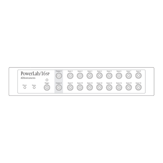
PowerLab/16
ADInstruments
Power
Status
MacLab
System
®
A D I n s t r u m e n t s
, PowerLab/8
SP
Output 1
SP
Trigger
Output 2
SP
Trigger
Power
Status
Output 1
Input 1
Input 2
SP
Trigger
Output 2
Input 9
Input 10
, and PowerLab/16
SP
Input 1
Input 2
Output 1
Input 1
Input 5
Output 2
Input 3
Input 4
Input 5
Input 6
Input 11
Input 12
Input 13
Input 14
SP
models
SP
Input 3
Input 4
Input 2
Input 3
Input 4
Input 6
Input 7
Input 8
Input 7
Input 8
Input 15
Input 16
PowerLab
System
®
Advertisement
Table of Contents

Related Manuals for ADInstruments PowerLab/4SP

Summary of Contents for ADInstruments PowerLab/4SP
- Page 1 PowerLab Owner’s Guide for PowerLab/4 , PowerLab/8 , and PowerLab/16 models Output 1 Input 1 Input 2 Input 3 Input 4 PowerLab/4 ADInstruments Trigger Output 2 Power Status Output 1 Input 1 Input 2 Input 3 Input 4 PowerLab/8 ADInstruments...
- Page 2 Changes may have been made (ML785); PowerLab/16 (ML795) to the software and hardware it describes since then, though: ADInstruments reserves the right to Hardware: Michael Macknight, Boris Schlensky, alter specifications as required. Late-breaking Tim Spencer, Graham Milliken, Indulus Kradzins.
-
Page 3: Table Of Contents
2 Setting Up Problems: Windows 42 Self-Test 16 C Specifications The USB Connection 17 Connecting the PowerLab Using USB 18 PowerLab/4sp Specifications 47 USB Connection Rules 19 PowerLab/8sp Specifications 50 The SCSI Connection 20 PowerLab/16sp Specifications 53 SCSI Connection Rules 20... - Page 4 PowerLab Owner’s Guide...
-
Page 5: Safety Notes
Applicable Safety Standards When used with insulated transducers or ADInstruments isolated front-ends, PowerLab systems are safe for human connection. The ML132 Bio Amp, ML135 Dual Bio Amp, ML408 Dual Bio Amp/Stimulator, ML116 GSR Amp, ML117 BP Amp and ML180 front- ends conform to international safety requirements. -
Page 6: General Safety Instructions
Never use the PowerLab without a ground connection. Safety Symbol Explanation Every ADInstruments device designed for connection to humans, including the Bio Amp, BP Amp, GSR Amp and Stimulus Isolator, carries one or more of three safety symbols, as shown in Figure S–1. - Page 7 Figure S–1 Equipment safety symbols on ADInstruments devices designed for safe connection to humans BF symbol: Body- Warning symbol: see CF symbol: Cardiac- protected equipment documentation protected equipment The three symbols are: • BF (body protected) symbol . This means that the input connectors are suitable for connection to humans provided there is no direct electrical connection to the heart.
- Page 8 Preventative Inspection and Maintenance Both PowerLab systems and ADInstruments front-ends are maintenance free and do not require periodic calibration or adjustment to ensure medical safety. Internal diagnostic software performs system checks during power up and will report errors if a significant problem is found.
-
Page 9: Overview
C H A P T E R O N E Overview Your PowerLab recording unit, together with a range of specialised application programs, provides a versatile data recording and analysis system when used with a Windows or Macintosh computer. This chapter provides an overview of the PowerLab system and describes the basic features, connectors, and indicators of the SP series PowerLabs: the PowerLab/4 , PowerLab/8... -
Page 10: How To Use This Guide
PowerLab can and cannot do, but this is not a service manual: only an authorised ADInstruments distributor should attempt repairs. If you modify the recording unit yourself, you void any rights you have under warranty. -
Page 11: The Powerlab System
If anything is missing, or the PowerLab seems to be damaged in any way, or if no voltage, or the wrong voltage, is shown on the back panel of the unit, contact your authorised ADInstruments distributor immediately, and describe the problem. Arrangements can be made to replace or repair the PowerLab. -
Page 12: The Application Programs
Additional requirements for SCSI: An appropriate SCSI card and cable (we recommend that you use a card and cable supplied by ADInstruments — others may be suitable, but you should seek technical advice if in doubt); a software component called ASPI... -
Page 13: Adinstruments Front-Ends
PowerLabs. They are automatically recognised by the PowerLab system and seamlessly integrated into its programs, operating under full software control. Your ADInstruments distributor will have full information on available front-ends and their uses and specifications, and will be happy to discuss your requirements. - Page 14 BNC connectors (marked Input 1 to Input 4), with four alternative Pod (DIN) connectors, for recording external signals. Input 1 Input 2 Input 3 Input 4 Output 1 PowerLab/4 Figure 1–2 ADInstruments The front panel of the Trigger Output 2 PowerLab/4 Power Status Power Status light...
-
Page 15: Analog Inputs
Power and Status Indicators The Power indicator on the front panel is a green light, which simply shows that the PowerLab is getting power. The indicator next to it, the Status indicator, provides a visual indication of what the PowerLab is doing, and will flash different patterns and colours depending on the state of the PowerLab. -
Page 16: Analog Output
Pod connectors allow the connection of ADInstruments Pods — small, low-cost units that provide alternatives to front-ends for specific tasks, for use with precalibrated transducers and so on. (Pods are supported by Scope v3.6.3 and later, Chart for Macintosh v3.6.3 and later, and Chart for Windows v3.4.7 and later.) The Pod... -
Page 17: The Back Panel
Trigger The external trigger connector allows you to use a digital signal level to synchronise recording to an external event. This input can handle voltages of up to ±12 V. The threshold voltage (the voltage above which the trigger circuit activates) is 2.9 volts for the series PowerLabs. - Page 18 The I C output is a special port designed to connect to front-ends made by ADInstruments. It supplies power and communications. A PowerLab can have as many front-ends connected to it as it has analog inputs, roughly speaking. Note. You should not attempt to run...
-
Page 19: Digital Input And Output Ports
be provided through this bus, so it should not be used for third-party devices drawing more current. Digital Input and Output Ports The digital input and output connectors let you monitor and control external devices respectively with the PowerLab. These recording automation and control features are available in the Macintosh version of Chart, but not in the current version of Chart for Windows (v3.4), or in Scope. -
Page 20: Power Connections
Power Connections The power switch on the back right of the PowerLab turns the PowerLab on and off; the 3-pin IEC power socket is used to connect your PowerLab to a 3-pin earthed (grounded) power cable. Figure 1–6 Power The power switch, fuse holder, switch and power socket Fuse... - Page 21 400 mA (5 × 20 mm) slow blow • 220–240 V (voltage rating 250 V only) The correct voltage for your country is shown on the back of the PowerLab, by the power switch (see Figure 1–1, page 3). Cooling Fan series PowerLabs can generate a fair amount of heat, so all of them are fitted with a cooling fan.
- Page 22 PowerLab Owner’s Guide...
-
Page 23: Setting Up
C H A P T E R T W O Setting Up This chapter starts with the PowerLab’s internal self-test, then looks at the USB connection. It also looks at the SCSI connection in some detail, including connection and termination rules, and setting the SCSI ID number. -
Page 24: Self-Test
Self-Test Now that you are familiar with some of the features of your PowerLab, you should check that it is working properly before you connect it to your computer. The PowerLab performs a diagnostic self-test each time it is switched on, whether or not it is connected to a computer. -
Page 25: The Usb Connection
If the error pattern is not simple alternating red and yellow flashes, then something may be wrong with the hardware itself. The pattern of red flashes indicates the likely problem area to ADInstruments technicians. Take note of pattern, switch off your PowerLab, wait about five seconds, and then switch it back on. -
Page 26: Connecting The Powerlab Using Usb
A hub is simply a device that lets you extend the USB tree. It connects to a USB device such as the computer, and multiple USB devices (including other hubs) can connect to it in turn. It provides power for those attached devices that need it. -
Page 27: Usb Connection Rules
the letters ‘USB’ instead). USB cables are directional, and can only be connected one way: the narrow rectangular A plug connects to a hub (including the computer), and the squarer B plug with the bevelled top connects to a USB device, such as the PowerLab. Connecting Macintosh or Windows computers should be much the same in this case: just look for the icons. -
Page 28: The Scsi Connection
2. Never attempt to make your own USB cable, or modify one. USB is sensitive to cable impedances and cable lengths. Only use a certified USB cable from a reliable supplier, never a cheap brand or ‘something the workshop whipped up’. Your PowerLab is supplied with the proper USB cable. - Page 29 Up to 6 or 7 linked SCSI devices, each with a unique ID Figure 2–3 A SCSI chain: up to six (or seven) devices can be linked … to the computer Computer: reserves SCSI ID #7 for a SCSI card The last SCSI device host adapter, or #0 and #7 if SCSI is built in must be terminated...
-
Page 30: Setting The Scsi Id Number
(foil and braid), with twisted pairs and shielded connector hoods for the most Figure 2–4 reliable results. ADInstruments sells approved SCSI cables The SCSI ID switch Setting the SCSI ID Number Your PowerLab was set to a SCSI ID number of 4 at the factory before shipping. -
Page 31: Scsi Termination Rules
(ultra-wide SCSI and the like). SCSI cards and cables with which the PowerLab should work reliably are sold by ADInstruments. Make sure that you have the correct, 25-pin to 25-pin SCSI cable to connect up your PowerLab. -
Page 32: Connecting The Powerlab: Windows
Most modern PC computers should have SCSI available through a card (some have it built in). Not all SCSI cards are suitable, especially high-end ones (ultra-wide SCSI and the like). ADInstruments sells SCSI cards and cables with which the PowerLab should work reliably. - Page 33 SCSI Cards with Windows NT or Older Computers Windows 95 and 98 both come with a number of generic SCSI drivers already installed that should work with most cards, including any that ADInstruments supplies. Windows NT may not have the right Chapter 2 — Setting Up...
-
Page 34: Scsi Strikes Back
SCSI driver available, so the driver might have to be installed manually, perhaps from the original NT system CD. The SCSI card should have instructions on the driver it needs and how to install it. Older, pre-PCI computers require a special ISA or ISO bus SCSI card. Such a card should come with its own manual, and may take some effort to set up. -
Page 35: A Technical Aspects
A P P E N D I X Technical Aspects This appendix describes some of the important technical aspects of the PowerLab/4 , PowerLab/8 , and PowerLab/16 , to give some insight into how they work. You do not need to know the material here to use your PowerLab. - Page 36 The PowerLab can use SCSI or USB, whether built-in or via a card, to communicate with the computer. SCSI (small computer system interface) provides data transfer rates of up to 4 MB per second on fast computers. The lower-speed USB (universal serial bus) provides data transfer rates of up to 500 kB per second.
- Page 37 (analog-to-digital converter). The ADC can sample at up to 200,000 samples per second. The CPU assembles groups of samples into blocks and then transmits them to the computer, where the application program receives, records, and displays the data. Sampled data from the ADC are stored in FIFOs until the CPU is ready to read them.
- Page 38 voltage exceeds 2.9 volts. This signal is fed to circuitry that notifies the CPU that an external trigger event has been detected. The CPU then carries out the task for which the trigger is being used (such as pre-triggering or post-triggering). When the trigger threshold is crossed, the indicator beside the trigger connector glows yellow.
-
Page 39: The Analog Inputs
The PowerLab is also fitted with an I C front-end expansion port. front-end must be used, This 9-pin port supplies both power and control to ADInstruments such as the Bio Amp. front-ends using a 4-wire serial bus (two wires for standard I C and two control lines). - Page 40 measures the difference between the positive and negative inputs of a Pod connector, irrespective of ground. Differential signals can only be recorded using the Pod connectors on the PowerLab/4 ; the BNC analog inputs on the PowerLabs are all single-ended. It is important to note that the PowerLab grounds the inputs to amplifiers not in use.
-
Page 41: Powerlab Accuracy
(say at 20% and 80% of full scale) and recording the signal, you can use the units conversion feature of ADInstruments applications to convert and display transducer readings in the appropriate units. This will compensate for any minor inaccuracies in amplifier gain and transducer calibration. -
Page 42: The Analog Output
The PowerLab has an optically isolated external trigger input, thus there is no direct connection between the external trigger ground and the ground of the device connected to it. This removes ground noise and current problems, and improves static discharge immunity. In order for the external trigger to work, though, a voltage must be applied between the outer ring and the inner pin on the connector. -
Page 43: Connections
negative one. When Output 2 is used, the voltage outputs are inverted. When both output sockets are used, the stimulus is the difference between the voltages at the positive and negative outputs: you could generate up to a 20-volt pulse, given a ±10 V stimulus. The outputs can be used for independent stimulation in Scope and the Macintosh version of Chart, but not in the current version of Chart for Windows (v3.4). -
Page 44: I 2 C Expansion Port
I C port: it is designed for use only with ADInstruments front-ends. Only 50 mA maximum current can be provided through this bus, so it should not be used for third-party devices drawing more current. -
Page 45: Digital Input And Output Ports
Do not attempt to record from both the BNC and Pod connectors for an input at the same time, or the signals will compete. Pod connectors allow the connection of ADInstruments Pods — small, low-cost units that provide alternatives to front-ends for specific tasks, for use with precalibrated transducers and so on. - Page 46 connectors on the PowerLab/4 do not handle transducers directly unless the transducers are so labelled (unsuitable transducers will give a very weak signal). Transducers designed for direct connection can be provided with power and control, since the Pod connectors provide some functions of the I C output as well as alternative analog inputs to the BNC connectors.
-
Page 47: B Troubleshooting
If none of the solutions here or in the software guide appears to help, then consult your ADInstruments distributor. Problems: Macintosh Nearly all the problems that users encounter are connection problems and SCSI problems. - Page 48 PowerLab back on again. This should clear a temporary problem. If not, then the PowerLab may need repair. Take note of the flashing pattern, and consult your ADInstruments distributor. The computer refuses to boot with the PowerLab connected, or the computer can’t find the PowerLab...
- Page 49 • USB needs a Power Macintosh with Mac OS 8.5 or later; it simply will not work with earlier hardware, such as a 68K Macintosh, or earlier operating systems, such as System 7: use SCSI with these. The computer hangs up while recording, or there is data loss A poor connection between PowerLab and computer, or bad cable.
-
Page 50: Problems: Windows
also have effective low-level disk checking. The programs will probably fix the problems, or otherwise indicate what needs to be done (such as reinstalling the SCSI driver), and their manuals should explain the technical details involved. The PowerBook computer stops working normally, and instead shows a diamond with its SCSI ID number on screen The PowerBook is acting as a SCSI hard disk. - Page 51 ASPI is present by default in Windows 95 or later (although it could have been removed), but not in Windows NT 4. A version suitable for most SCSI cards supplied by ADInstruments is provided on the software CD. Other SCSI cards should come with instructions on what to do.
- Page 52 reliably with a card we did not supply, and some computers and SCSI adapter cards just won’t work together. • Try another card, preferably one we supplied. Ask your PC technical support person or IS manager to check compatibility. A poor connection between PowerLab and computer, or bad cable. •...
- Page 53 • Check that each device has a unique ID number and that the SCSI chain is terminated correctly. (As a last resort, if the PowerLab is the only connected SCSI device, try leaving it unterminated.) The PowerLab has an internal problem or has ‘hung’. •...
- Page 54 reliably with a card we did not supply, and some computers and SCSI adapter cards just won’t work together. • Try another card, preferably one we supplied. Ask your PC technical support person or IS manager to check compatibility. A poor connection between PowerLab and computer, or bad cable. •...
-
Page 55: C Specifications
A P P E N D I X Specifications PowerLab/4 Specifications Input Number of inputs: Input configuration: Single-ended or differential (the latter only through the Pod connectors) ±2 mV to ±10 V full scale in 12 steps Amplification ranges: ± 10 V ±... - Page 56 DC drift: Software-corrected CMRR (differential): 96 dB @ 50 Hz (typical) Input crosstalk: –110 dB typical < 1 µV Input noise: referred to input Pod connectors: Combine power, I C and single-ended or differential analog input signals on one connector, support Pods, particular transducers, etc.
- Page 57 ±1 LSB (from 0 °C to 70 °C) Linearity error: ±200 mV to ±10 V full scale in six steps Output ranges: ± 10 V ± 5 V ± 2 V ± 1 V ± 500 mV ± 200 mV External Trigger Trigger threshold: +2.9 V (TTL compatible)
-
Page 58: Powerlab/8Sp Specifications
Physical Configuration Dimensions (w × h × d): 300 mm × 60 mm × 300 mm (11.8" × 2.4" × 11.8") Weight: 4.5 kg (9 lb 13 oz) Operating voltage: 220–240 V or 110–120 V (internally set) Nominal power needs: 12.5 VA (no front-ends attached) Maximum power needs: 18 VA (full complement of front-ends) - Page 59 Low-pass filtering: 1, 2, 5, 10, or 20 kHz (software-selectable) AC coupling: DC or 0.1 Hz (software-selectable) 20 kHz @ ±10 V full scale, all gain ranges Frequency response (–3 dB): DC drift: Software-corrected CMRR (differential): 96 dB @ 50 Hz (typical) Input crosstalk: –110 dB typical <...
- Page 60 ±200 mV to ±10 V full scale in six steps Output ranges: ± 10 V ± 5 V ± 2 V ± 1 V ± 500 mV ± 200 mV External Trigger Trigger threshold: +2.9 V (TTL compatible) Hysteresis: 1.1 V (turns off at +1.8 V) Input load: 1 TTL load ±12 V...
-
Page 61: Powerlab/16Sp Specifications
Physical Configuration Dimensions (w × h × d): 300 mm × 60 mm × 300 mm (11.8" × 2.4" × 11.8") Weight: 4.8 kg (10 lb 8 oz) Operating voltage: 220–240 V or 110–120 V (internally set) Nominal power needs: 17 VA (no front-ends attached) Maximum power needs: 30 VA (full complement of front-ends) - Page 62 Low-pass filtering: 1, 2, 5, 10, or 20 kHz (software-selectable) AC coupling: DC or 0.1 Hz (software-selectable) 20 kHz @ ±10 V full scale, all gain ranges Frequency response (–3 dB): DC drift: Software-corrected CMRR (differential): 96 dB @ 50 Hz (typical) Input crosstalk: –110 dB typical <...
- Page 63 ±200 mV to ±10 V full scale in six steps Output ranges: ± 10 V ± 5 V ± 2 V ± 1 V ± 500 mV ± 200 mV External Trigger Trigger threshold: +2.9 V (TTL compatible) Hysteresis: 1.1 V (turns off at +1.8 V) Input load: 1 TTL load ±12 V...
- Page 64 220–240 V: 400 mA (5 × 20 mm) slow blow (voltage rating 250 V only) 0 to 35 °C, 0 to 90% humidity (non- Operating temperature range: condensing) ADInstruments reserves the right to alter these specifications at any time. PowerLab Owner’s Guide...
-
Page 65: Glossary
Glossary This covers terms used in this owner’s guide, volts. Inputs can be either single-sided or those for ADInstruments front-ends, and the differential (the latter only in the case of the user’s guides for ADInstruments software. Pod connectors). General and specific computer terminology should be covered in the material that came analog output. - Page 66 bus. A data-carrying electrical pathway. envelope form. The overall shape of a signal, outlined by the minimum and maximum Chart. An application supplied with a recorded values. Often used to display PowerLab that emulates a multi-channel quickly changing signals. chart recorder, with other powerful options. (Macintosh and Windows versions differ.) excitation voltage.
- Page 67 front-end. An ancillary device that extends Macintosh. A family of Apple computers PowerLab capabilities, providing additional with built-in graphics and an elegant user signal conditioning and features for interface. Of the Mac OS (operating system) specialised work. Front-ends are recognised versions, System 7 is needed and System 7.6 automatically by the PowerLab system and recommended normally;...
- Page 68 PowerChrom program. It provides general- TChart. A simplified version of the Chart purpose manual or automatic recording and program once used for teaching. Its manual analysis of chromatographic peaks. of experiments is now available for Chart. PowerLab. The PowerLab hardware unit is a terminator.
-
Page 69: Index
Index contacting ADInstruments ii cooling fan 13 ADC (analog-to-digital converter) 28 ADInstruments contacts ii – analog input 7 – analog output 8 DAC (digital-to-analog converter) 30 analog-to-digital converter 29 DC drift 32 ASPI 4 digital input 31 digital output 31 digital-to-analog converter 30 –... - Page 70 – – Pod connection 7 technical specifications Pods 8 – PowerLab/16sp 53 portable computers 24 – PowerLab/4sp 47 Power indicator 7 – PowerLab/8sp 50 power switch 12 termination rules for SCSI 23 PowerLab transistor–transistor logic 33 accuracy 33 trigger 9 –...
-
Page 71: Licensing & Warranty Agreement
Licensing & Warranty Agreement Extent This Agreement is between ADInstruments Pty If problems arise with an ADI product, ADI will Ltd [‘ADI’] and the purchaser [‘the Purchaser’] of make all reasonable efforts to fix them. This service any ADI product — software, hardware, or both —... - Page 72 Hardware Warranty Technical Support ADI warrants that the hardware purchased by the Once a customer registration form has been filled Purchaser shall be free of defects in material and out and sent in, the Purchaser is entitled to free workmanship for one year from its date of technical support for any ADI product for one year purchase.
Need help?
Do you have a question about the PowerLab/4SP and is the answer not in the manual?
Questions and answers