4RF Aprisa XE User Manual
4rf aprisa xe fixed point-to-point digital radio link
Hide thumbs
Also See for Aprisa XE:
- User manual (182 pages) ,
- Technical paper (15 pages) ,
- Quick start manual (2 pages)
Table of Contents
Advertisement
Quick Links
Advertisement
Table of Contents

Related Manuals for 4RF Aprisa XE


Summary of Contents for 4RF Aprisa XE
- Page 1 Aprisa XE User Manual Version 7.3.1 September 2006...
- Page 2 Copyright © 2001-2005 4RF Communications Ltd. All rights reserved. This document is protected by copyright belonging to 4RF Communications Ltd and may not be reproduced or republished in whole or part in any form without the prior written permission of 4RF Communications Ltd.
- Page 3 ETSI radio specifications and suitably displays the CE logo. Other bands are compliant to the same radio performance specifications as adapted by 4RF and therefore may be used in regions where compliance requirements demand CE performance at other frequencies.
- Page 4 Svensk Härmed intygar 4RF Communications Ltd att denna Aprisa™ Radio står I överensstämmelse med de väsentliga egenskapskrav och övriga relevanta bestämmelser som framgår av direktiv 1999/5/EG. A formal Declaration of Conformity document is shipped with each Aprisa XE terminal.
-
Page 6: Table Of Contents
Contents | v Contents Getting started ....................11 Introduction .....................15 About this manual......................15 What it covers ......................15 Who should read it ....................15 Contact us ......................15 What's in the box ......................15 Aprisa CD contents ....................16 Accessory kit ......................17 Preparation ......................19 Path planning ........................19 Antenna selection and siting ................19 Coaxial feeder cables...................22 Link budget......................22... - Page 7 Contents | vi Managing the terminal..................51 The setup menu ......................51 4RF SuperVisor......................53 Logging in......................54 Logging out ......................54 SuperVisor opening page....................55 Changing the terminal’s IP address ................56 Setting up users ......................57 User groups......................57 Adding a user .......................57 Disabling a user ....................58 Deleting a user .....................58...
- Page 8 Contents | vii Opening the Cross Connections application ............122 The Cross Connections page................123 Setting the terminal's address ................125 Management and user ethernet capacity............125 Setting card types ....................126 Getting cross connection configuration from the terminals ........126 Creating cross connections................127 Sending cross connection configuration to the terminals ........130 Saving cross connection configurations.............130 Using existing cross connection configurations ..........130 Printing the cross connection configuration ............131...
- Page 9 Contents | viii 13. Maintenance ....................175 Routine maintenance ....................175 Terminal upgrades ......................176 Upgrade process....................176 Installing RF synthesizer configuration files ............176 Upgrading the terminal using TFTP ..............177 Upgrading the terminal by uploading system files..........182 Viewing the image table ..................187 Changing the status of an image file..............188 Rebooting the terminal ....................189 Support summary ......................190 Installing interface cards....................191...
- Page 10 Contents | ix External alarm inputs ..................233 Remote terminal alarms ..................233 Cross connect alarms ..................233 MHSB alarms .....................233 17. Country specific settings ................235 18. Specifications....................237 RF specifications ......................237 System performance specifications................238 Interface specifications....................244 Ethernet interface....................244 QJET Quad E1 / T1 interface................244 Q4EM Quad 4 wire E&M interface ..............245 DFXO Dual foreign exchange office interface............246 DFXS Dual foreign exchange subscriber interface ..........248...
-
Page 12: Getting Started
Getting started | 11 Getting started This section is an overview of the steps required to commission a link in the field. Phase 1: Pre-installation Confirm path planning. Page 19 Ensure that the site preparation is complete: Page 22 Power requirements Tower requirements Environmental considerations, for example, temperature control Rack space... - Page 13 Getting started | 12 Phase 3: Establishing the link If you don't know the terminal's IP address : Page 52 Connect the setup cable between the terminal's Setup port and the PC using accessory kit adaptor. Use HyperTerminal to confirm the IP settings for the terminal: Local IP address Local subnet mask Remote terminal IP address...
- Page 14 Getting started | 13 Phase 4: Configuring the traffic Confirm that the interface hardware and software slot configurations match. Confirm the interface card settings. Page 79 Open the Cross Connections application and configure the cross Page 122 connections: Download the configuration. Confirm or modify the traffic cross connections.
-
Page 16: Introduction
Contact us If you experience any difficulty installing or using Aprisa XE after reading this manual, please contact Customer Support or your local 4RF representative. Our area representative contact details are available from our website:... -
Page 17: Aprisa Cd Contents
User manual — an electronic (PDF) version for you to view online or print. Product collateral — application overviews, product description, case studies, and white papers. Tools Surveyor - a path propagation calculator developed by 4RF (see "Path planning" on page 19). -
Page 18: Accessory Kit
Introduction | 17 Accessory kit The accessory kit contains the following items: Setup cable (RJ-45) and adaptor Mounting brackets and screws Hardware kit (includes Allen key for fascia screws) Alarm cable (RJ-45) - Page 19 Introduction | 18 Ground cable DC power cable (for use with the -48 VDC and -24 VDC power supplies) AC power cable (for use with the 110 / 230 VAC power supply)
-
Page 20: Preparation
You can also use Surveyor to help you with path feasibility planning. Surveyor is a path propagation calculator developed by 4RF to assist path planners quickly and efficiently verify the viability of point-to-point transmission links deploying the Aprisa™ microwave radio systems. - Page 21 Preparation | 20 Yagi antennas Factor Explanation Frequency Often used in 330-960 MHz bands Gain Varies with size (typically 11 dBi to 16 dBi) Stackable gain increase 2 Yagi antennas (+ 2.8 dB) 4 Yagi antennas (+ 5.6 dB) Wind loading Less than a parabolic grid antenna Tower aperture required Unstacked: Less than a parabolic grid...
- Page 22 Preparation | 21 Corner reflector antennas Factor Explanation Frequency Often used in 330-960 MHz bands Gain Typically 10 dBd Wind loading Less than a parabolic grid antenna Tower aperture required About the same as a parabolic grid antenna Size Range from 0.36 m to 0.75 m in length Front to back ratio High (typically 30 dB) Beamwidth...
-
Page 23: Coaxial Feeder Cables
Preparation | 22 Coaxial feeder cables To ensure maximum performance, it is recommended that you use good quality low-loss coaxial cable for all feeder runs. For installations requiring long antenna cable runs, use Andrew Heliax™ or equivalent. When using large diameter feeders, use a short flexible jumper cable between the feeder and the terminal to reduce stress on the antenna port connector. -
Page 24: Site Requirements
Preparation | 23 Site requirements Power supply Ensure that the correct power supply is available for powering the terminal. The nominal input voltage for a terminal is 12, 24 or 48 volts DC or 115 / 230 volts AC rms. The DC supply voltage is factory preset at time of order and cannot be adjusted in the field. -
Page 25: Earthing And Lightning Protection
Preparation | 24 Earthing and lightning protection Warning: Lightning can easily damage electronic equipment. To avoid this risk, install primary lightning protection devices on any interfaces that are reticulated in the local cable network. You should also install a coaxial surge suppressor on the antenna port of the duplexer Earth the antenna tower, feeders and lightning protection devices in accordance with the appropriate local and national standards. -
Page 26: About The Terminal
About the terminal | 25 About the terminal Introduction The terminals operate in a number of frequency bands from 300 MHz up to 2.7 GHz carrying ethernet, voice and data traffic over distances up to 100 kilometres. They are designed to meet the demands of a wide range of low to medium capacity access and backhaul applications. -
Page 27: Modules
About the terminal | 26 Modules The terminal is modular in design, which helps reduce mean time to repair (MTTR). It is designed for 19-inch rack mounting and is only 2U high for standard configurations. The five main modules housed inside the chassis are the transceiver, modem, motherboard, power supply, and duplexer. -
Page 28: Front Panel Connections And Indicators
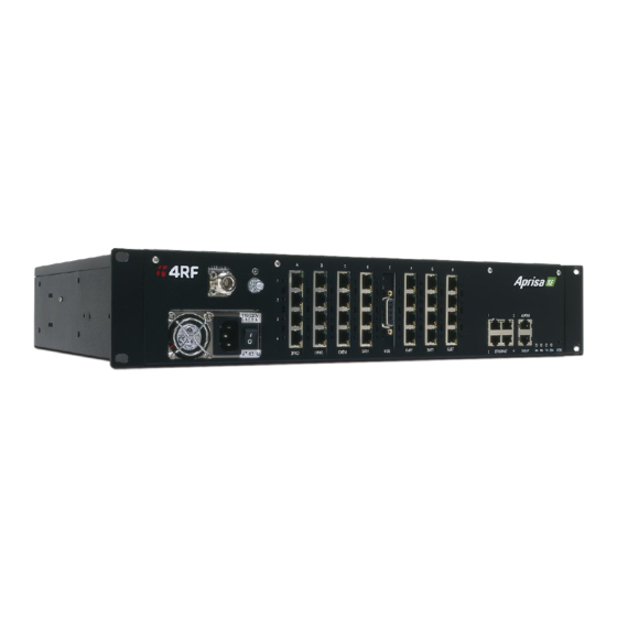
About the terminal | 27 Front panel connections and indicators All connections to the terminal are made on the front panel of the terminal. Label Description AC or DC power input DC and AC power supplies are available (AC is shown) Safety earth stud An M5 stud for connection to an external protection ground for protection against electric shock in case of a fault. -
Page 29: Interface Card Types
About the terminal | 28 Interface card types Each terminal has eight interface slots labeled A to H. Each slot can be fitted with any interface card type. Typically, the terminal is delivered pre-configured with the requested interface cards. The following interface card types are currently available: Name Interface card type Function... -
Page 30: Mounting And Installing The Terminal
Warning: You must comply with the safety precautions in this manual or on the product itself. 4RF does not assume any liability for failure to comply with these precautions. Required tools No special tools are needed to install the terminal other than those required to physically mount the terminal into the rack. -
Page 31: Installing The Antenna And Feeder Cable
Mounting and installing the terminal | 30 Installing the antenna and feeder cable Carefully mount the antenna following the antenna manufacturers' instructions. Run feeder cable from the antenna to the terminal mounting location. Lightning protection must be incorporated into the antenna system. For more information, please contact Customer Support. -
Page 32: External Alarms
Mounting and installing the terminal | 31 External alarms Two external alarm inputs and four external alarm outputs are provided on the RJ-45 ALARM connector on the front panel. These enable an internal alarm to provide an external alarm to the network operator's existing network management system via contact closure or opening, or for an external alarm to be transported via the radio link. -
Page 33: Interface Cabling
Mounting and installing the terminal | 32 Interface cabling All interface cabling connections are made with RJ-45 male connectors which plug into the front of the interface cards (see “Interface connections” on page 211). The cabling to the QJET, DFXO and DFXS interface cards must have a minimum conductor size of 0.4 mm2 (26 AWG). - Page 34 Mounting and installing the terminal | 33 DC Cabling The DC power input is terminated on the front panel of the terminal with two high-current M3 screw clamps for the positive and negative DC input and a M5 stud for the earth connection. The DC power cables have pre-terminated lugs to fit into the power input M3 screw clamps on one end and bare wire at the other end.
- Page 35 Mounting and installing the terminal | 34 12 VDC cable The 12 VDC power supply is supplied with a 3 metre red/black cable of two pairs of 2.3 mm strands of 0.2 mm ) making a total of 4.6 mm per connection.
-
Page 36: Ac Power Supply
Mounting and installing the terminal | 35 AC power supply There is one AC power supply for the terminal. This AC power supply is auto-sensing to operate with a nominal input voltage of 115 Vrms or 230 Vrms. The power input is terminated on the front panel of the terminal using a standard IEC plug. This power supply has a power on/off switch. -
Page 37: Safety Earth
Mounting and installing the terminal | 36 Safety earth The terminal chassis must have a protection / safety earth connected between the terminal earth stud and a common protection earth in the rack. The DC power input can be either positive grounded or negative grounded depending on the power supply system available. -
Page 38: Bench Setup
Mounting and installing the terminal | 37 Bench setup Before installing the link in the field, it is recommended that you bench-test the link. A suggested setup for basic bench testing is shown below: When setting up the equipment for bench testing, note the following: Earthing—the terminal should be earthed at all times. -
Page 40: Connecting To The Terminal
Connecting to the terminal | 39 Connecting to the terminal Connecting to the terminal's setup port You can configure basic terminal settings by connecting to the terminal using the Setup cable. This can be useful if you need to confirm the terminal's IP address, for example. You can password-protect the setup menu to prevent unauthorized users from modifying terminal settings. - Page 41 Connecting to the terminal | 40 Configure the PC COM port settings Terminal emulation software e.g. HyperTerminal is used to setup the basic configuration of a terminal. The PC's COM port settings must be setup as follows: Bits per second 115200 Data bits Parity...
- Page 42 Connecting to the terminal | 41 4. Set the COM Port settings as follows: 5. When you have completed the settings, click OK, which will open the HyperTerminal window. 6. Apply power to the terminal. Note: If power was applied to the terminal before launching HyperTerminal, hit the Enter key to initiate the link.
-
Page 43: Connecting To The Terminal's Ethernet Interface
Connecting to the terminal | 42 Connecting to the terminal's ethernet interface The main access to a terminal for management is with the ethernet interface using standard IP networking. There should be only one ethernet connection from the terminal to the management network. -
Page 44: Pc Requirements For Supervisor
Connecting to the terminal | 43 PC requirements for SuperVisor SuperVisor requires the following minimum PC requirements: Microsoft Windows 95/98, 2000, NT or XP Personal computer with 800 MHz Pentium III 128 MB of RAM (the Java plug-in requires at least 32 MB of physical RAM) 108 MB of free hard disk space Ethernet interface (Local Area Network) COM port... -
Page 45: Pc Settings For Supervisor
Connecting to the terminal | 44 PC settings for SuperVisor To change the PC IP address: If your PC has previously been used for other applications, you may need to change the IP address and the subnet mask settings. You will require Administrator rights on your PC to change these. Windows XP example: Configure IP settings 1. - Page 46 Connecting to the terminal | 45 To change the PC connection type: If your PC has previously been used with Dial-up connections, you may need to change your PC Internet Connection setting to 'Never dial a connection'. Windows XP example: Configure Windows to Never Dial a Connection 1.
- Page 47 Connecting to the terminal | 46 To change the PC pop-up status: Some functions within SuperVisor require Pop-ups enabled e.g. saving a MIB Windows XP example: Configure explorer to enable Pop-ups 1. Open the 'Control Panel'. 2. Open 'Internet Options' and click on the 'Privacy' tab. 3.
-
Page 48: Ip Addressing Of Terminals
Connecting to the terminal | 47 IP addressing of terminals When logging into a link, it is important to understand the relationship between the Local / Remote and the Near end / Far end terminals. The Near end terminal is the terminal that has its ethernet port physically connected to your IP network. -
Page 49: Network Ip Addressing
Connecting to the terminal | 48 Network IP addressing Same subnet as local PC The following diagram shows a link interconnected on the same subnet as the local PC terminal used for configuration. In this example, the local PC, as well as the local and remote terminals, are on the same subnet and therefore have the same subnet mask 255.255.255.0. -
Page 50: Different Subnet As Local Pc
Connecting to the terminal | 49 Different subnet as local PC The following diagram shows a link interconnected on a different subnet as the local PC used for configuration, and communicating through a network. This can be achieved on the condition that network router(s) 1 and 2 are programmed to recognize each other and the various subnets on the overall network. -
Page 52: Managing The Terminal
Provide basic access to the terminal to set IP addresses Check or set basic settings of the terminal 4RF SuperVisor is an embedded element manager for the Aprisa XE terminal which is used to: Configure radio and interface parameters Setup cross connections between traffic interfaces... - Page 53 Managing the terminal | 52 To get or set the IP address of a terminal using setup To get the IP address of a terminal using setup: 1. At the prompt, type 1 and enter. The following information appears: the IP addresses of the local and remote terminals the subnet mask and gateway of the local terminal the TFTP of the remote terminal To set the IP address of a terminal using setup:...
-
Page 54: 4Rf Supervisor
Managing the terminal | 53 4RF SuperVisor 4RF SuperVisor management software is pre-loaded into an integrated web-server within the terminal. SuperVisor runs on any Java-enabled web browser. You can use SuperVisor to: display and configure terminal parameters view the terminal alarms... -
Page 55: Logging In
Managing the terminal | 54 Logging in The maximum number of concurrent users that can be logged into a terminal is 5. If SuperVisor is inactive for a period of 30 minutes, the terminal will automatically log out the user. To log in to SuperVisor: 1. -
Page 56: Supervisor Opening Page
Managing the terminal | 55 SuperVisor opening page SuperVisor terminal status and menu bar The terminal status and menu bar at the top of the screen shows the name of the terminal and three status indicators for both the local and remote terminals. The indicators reflect the status LED indicators on the front panel of terminal. -
Page 57: Changing The Terminal's Ip Address
Managing the terminal | 56 Changing the terminal’s IP address You can use SuperVisor to change the IP address of the terminal from the default. Alternatively, you can assign the IP address using the SETUP port (see "To get or set the IP address of a terminal using setup”... -
Page 58: Setting Up Users
Managing the terminal | 57 Setting up users Note: You must login with 'admin' privileges to add, disable, delete a user or change a password. User groups There are three pre-defined user groups to allocate access rights to users. These user groups have associated default user names and passwords of the same name. -
Page 59: Disabling A User
Managing the terminal | 58 Disabling a user 1. Select Local or Remote > Maintenance > User Admin > User Table. 2. Select the user who you want to disable. 3. Click Edit to display the User details and set Enabled to 'No'. 4. -
Page 60: Changing Passwords
Managing the terminal | 59 Changing passwords 1. Select Local or Remote > Maintenance > User Admin > User Table. 2. Select the user whose password you want to change and click Edit. 3. Enter the new Password and the new Confirm Password. A password can be up to 32 characters but cannot contain back slashes, forward slashes, spaces, tabs, single or double quotes. -
Page 62: Configuring The Terminal
Configuring the terminal | 61 Configuring the terminal Configuring the RF settings The RF settings are factory-configured before dispatch to the customer requirements. However, you can change the RF settings, if required. Select Link or Local or Remote > Terminal > Basic: Note: Transmit frequency, transmit power, channel size, modulation and antenna polarization would normally be defined by a local regulatory body and licensed to a particular user. -
Page 63: Transmit Power
The transmitter power adjustment range varies depending on the Modulation type and frequency band of the terminal (see “System performance specifications” on page 238). Channel size The RF channel size is a factory-configured setting determined by the Aprisa XE hardware option. Modulation type Both terminals must be set to the same modulation type. -
Page 64: Modem Performance Settings
Configuring the terminal | 63 Modem Performance Settings Select Local or Remote > Performance > Summary and Quick Links of Modem Performance Settings. There are two Modem Performance Settings, Modem QPSK Coding and Modem Interleaver Mode. Modem QPSK Coding When the Modulation type is set to QPSK, the default QPSK Coding setting is ‘Non-Gray Coded’ but the QPSK Coding can use ‘Gray Coded’... -
Page 65: Entering Terminal Information
2. Enter a unique Terminal ID. 3. Enter the Location of the terminal. 4. Enter a contact name or an email address in Contact Details. The default value is ‘support@4RF.com’. 5. Click Apply to apply changes or Reset to restore the previous configuration. -
Page 66: Configuring The Ip Settings
Configuring the terminal | 65 Configuring the IP settings 1. Select Link or Local or Remote > Terminal > Advanced. 2. Select either DHCP or Static IP addressing. 3. If you select Static IP, you must also: Enter the IP Address for the terminal assigned by your site network administrator. Use the standard format xxx.xxx.xxx.xxx. -
Page 67: Saving The Terminal's Configuration
Configuring the terminal | 66 Saving the terminal's configuration Note: To save cross connection configurations, see page 130. To save a configuration: 1. Ensure you are logged in with either 'modify' or 'admin' privileges. 2. Select Local > Maintenance > Config Files > Save MIB. 3. -
Page 68: Snmp (Simple Network Management Protocol)
Configuring the terminal | 67 SNMP (Simple Network Management Protocol) In addition to web-based management (SuperVisor), the terminal can also be managed using the Simple Network Management Protocol (SNMP). MIB files are supplied, and these can be used by a dedicated SNMP Manager, such as Castle Rock's SNMPc (www.castlerock.com), to access most of the terminal's configurable parameters. -
Page 69: Snmp Access Controls
The Community string is usually different for Read Only and Read/Write operations. There is no default 'public' community string for an access control, but a 'public' community string can be entered which will have full MIB access, including the 4RF MIB. 4. Click Add. -
Page 70: Snmp Trap Destinations
Configuring the terminal | 69 SNMP trap destinations To add a trap destination: 1. Click on the ‘Add SNMPv1’ button to enter a SNMPv1 trap destination or click on the ‘Add SNMPv2c’ button to enter a SNMPv2c trap destination. The differences between SNMPv1 and SNMPv2c are concerned with the protocol operations that can be performed. -
Page 71: Viewing The Snmp Traps
Configuring the terminal | 70 Viewing the SNMP traps Any event or alarm in the SNMP objects list can be easily viewed. This also enables you to verify, if required, that SNMP traps are being sent. Select Local > Maintenance > SNMP > View Traps. Viewing the SNMP MIB details This is useful to see what MIB (Management Information Base) objects the terminal supports. -
Page 72: Setting The Terminal Clock Sources
Configuring the terminal | 71 Setting the terminal clock sources Select Link or Local or Remote > Terminal > Clocking The current selected clock source and the current states of the primary and secondary network clocks are shown: Clock State Clock State Description Inactive This clock source is either not configured at all, or is not in current use... - Page 73 Configuring the terminal | 72 To select the terminal clock source: The Clock Source selected for the terminal will be used to clock all interface ports requiring clocking and send a clocking signal over the RF link. Select Link or Local or Remote > Terminal > Clocking > Clock Source and select one of the following: Clock Source Terminal Clocking Network...
-
Page 74: Configuring The Rssi Alarm Threshold
Configuring the terminal | 73 Configuring the RSSI alarm threshold The threshold (in dB) at which the RSSI alarm activates can be set for each of the modulation types over the adjustment range of -40 dBm to -110 dBm and the default values are as per the following screen shot. -
Page 75: Configuring The External Alarms
Configuring the terminal | 74 Configuring the external alarms Each terminal has two external alarm inputs and four external alarm outputs, terminated on the ALARM RJ-45 connector on the terminal front panel. Each external alarm input can activate the Major / Minor terminal alarm or be mapped to a remote terminal external alarm output. - Page 76 Configuring the terminal | 75 1. Select the Display Locally setting for each alarm input. Display Locally External Alarm Input Function The external alarm input does not generate an alarm on the local Default terminal, does not appear in the ‘Alarm Table’ or ‘Alarm History’, and shows as grayed out on the ‘Alarm Summary’.
-
Page 77: Configuring The External Alarm Outputs
Configuring the terminal | 76 Configuring the external alarm outputs To configure the External Alarm Outputs: Select Link or Local or Remote > Alarms > Ext Alarm Outputs Note: When the terminal MHSB mode is enabled, the external alarm output 4 is used by the protection switch system so is not available for user alarms. -
Page 78: Configuring The Traffic Interfaces
Configuring the traffic interfaces | 77 Configuring the traffic interfaces Important: When configuring a link, it is important that you configure the remote terminal first as the new configuration may break the management connection to the remote terminal. Once the remote terminal has been configured, the local terminal should be configured to match the remote terminal. - Page 79 Configuring the traffic interfaces | 78 The interface type for each slot that has been configured with the capacity used by each port. Total Capacity. The total capacity of the radio link. Ethernet Capacity. The capacity allocated to the Ethernet traffic over the radio link. This includes the user and management capacity assigned.
-
Page 80: Configuring The Traffic Interfaces
Configuring the traffic interfaces | 79 Configuring the traffic interfaces Important: Before you can configure the traffic interfaces, the interface cards must be already installed (see "Installing interface cards” on page 191). Configuring each traffic interface involves the following steps (specific instructions for each interface card follow this page). -
Page 81: Ethernet
Configuring the traffic interfaces | 80 Ethernet In the default mode the Ethernet switch passes IP packets (up to 1522 bytes) as it receives them. However, using SuperVisor you can configure VLAN, QoS and port speed settings to improve how IP traffic is managed. - Page 82 Configuring the traffic interfaces | 81 Specifying the VLAN ID for the Ethernet ports Each Ethernet port can be configured with one of five VLAN IDs. You can configure each of the physical ports, numbered 1 to 4 with a VLAN ID (numbered User1 to User4 and User+Mgmt). These VLAN IDs are applied at the ingress port and only used internally across the link.
-
Page 83: Quality Of Service
Configuring the traffic interfaces | 82 Quality of Service Quality of Service (QoS) enables network operators to classify traffic passing through the Ethernet switch into prioritized flows. Each port can have a priority tag set at the ingress port, or it can be read directly from the Ethernet traffic. - Page 84 Configuring the traffic interfaces | 83 4. Select the Priority Queue Scheduling. There are two methods for transmitting the Ethernet traffic queues across the link: Strict: the queue is transmitted based on the priority. The first queue transmitted is the highest priority queue and the terminal will not transmit any other traffic from any other queue until the highest priority queue is empty.
- Page 85 Configuring the traffic interfaces | 84 Configuring the Ethernet ports for QoS Each Ethernet port can be configured for Ingress Rates and Priority queues. To configure the Ethernet ports for QoS: 1. Select Link or Local or Remote > Interface > Ethernet Settings. 2.
- Page 86 Configuring the traffic interfaces | 85 3. Select the required Ingress Rate for this port. The ingress rate (input data rate) limits the rate that traffic is passed into the port. Operators can protect the terminal’s traffic buffers against flooding by rate-limiting each port. Ingress Rate Unlimited Default...
-
Page 87: Viewing The Status Of The Ethernet Ports
Configuring the traffic interfaces | 86 Viewing the status of the ethernet ports Select Link or Local or Remote > Interface > Switch Summary. For each port the following is shown: Speed — the data rate (in Mbit/s) of the port. Duplex —... -
Page 88: Qjet Port Settings
Configuring the traffic interfaces | 87 QJET port settings 1. Select Link or Local or Remote > Interface > Interface Summary, then select the QJET interface and click Configure Interface. 2. Select the QJET port to be configured and click Edit. 3. - Page 89 Configuring the traffic interfaces | 88 5. Set the QJET interface Clock Source. One interface port in each terminal can be set to 'primary' and one interface port to 'secondary' (an error message will appear if you try to set more than one primary source or more than one secondary source).
-
Page 90: Q4Em Port Settings
Configuring the traffic interfaces | 89 Q4EM port settings 1. Select Link or Local or Remote > Interface > Interface Summary, select the Q4EM interface, and click Configure Interface. 2. Select the Q4EM port to be configured, and click Edit. 'Slot' shows the slot the Q4EM interface card is plugged into in the terminal (A –... - Page 91 Configuring the traffic interfaces | 90 4. Set the Q4EM E wire interface to either Normal or Inverted. This determines the state of the CAS bit relative to the state of the E wire: E wire output CAS bit Normal CAS bit Inverted (default) Output Active...
-
Page 92: Dfxo / Dfxs Loop Interface Circuits
Configuring the traffic interfaces | 91 DFXO / DFXS loop interface circuits Function The function of DFXO / DFXS 2 wire loop interface circuits is to transparently extend the 2 wire interface from the exchange line card to the telephone / PBX, ideally without loss or distortion. The DFXO interface simulates the function of a telephone and a DFXS interface simulates the function of an exchange line card. - Page 93 The line termination impedance is not the same as the hybrid balance impedance network (Zb) but can be set to the same value. Changing the DFXO / DFXS impedance setting on the Aprisa XE changes both the line termination impedance and the hybrid balance impedance to the same value.
- Page 94 (sometimes called singing). Typically, an end to end 2 wire voice circuit is engineered to have a 2-3 dB loss in both directions of transmission. Derived System Level Plan Overall Loss = 8.0 dB Aprisa XE Exchange DFXO DFXS Line Card Interface Interface 0.0 dBm...
-
Page 95: Dfxs Port Settings
Configuring the traffic interfaces | 94 DFXS port settings 1. Select Link or Local or Remote > Interface > Interface Summary, then select the DFXS interface and click Configure Interface. 2. Select the DFXS port to configure, and click Edit. 'Slot' shows the slot the DFXS interface card is plugged into in the terminal (A –... - Page 96 Configuring the traffic interfaces | 95 3. Set the DFXS Input Level and the Output Level required: Signal Direction Level adjustment range Default setting Input Level (L -9.0 dBr to +3.0 dBr in 0.5 dB steps +1.0 dBr Output Level (L -9.5 dBr to +2.5 dBr in 0.5 dB steps -6.0 dBr In the example shown below, the Customer Premises Equipment is a telephone connected to a...
- Page 97 Configuring the traffic interfaces | 96 5. Select the DFXS Control. The DFXS Control page sets values for both ports on the DFXS card. The cards are shipped with the default values shown in the illustration below: 'Slot' shows the slot the DFXS interface card is plugged into in the terminal (A – H). 6.
- Page 98 Configuring the traffic interfaces | 97 7. Select the DFXS Line Impedance This option sets the DFXS line termination impedance and the hybrid balance impedance to the same value. Selection Description 600 Ω Standard equipment impedance Default 600 Ω + 2.16 uF Standard equipment impedance with low frequency roll-off 900 Ω...
- Page 99 Configuring the traffic interfaces | 98 10. Set the DFXS Ringer Output Voltage. This option sets the DFXS open circuit Ringing Output Voltage which is sourced via an internal ringing resistance of 178 Ω per port. The DC offset on the AC ringing signal enables ring trip to occur with a DC loop either during ringing cycles.
- Page 100 Configuring the traffic interfaces | 99 12. Select the DFXS Billing Tone Level. This option sets the DFXS billing tone output level which is defined as the voltage into 200 Ω with a source impedance equal to the Line Impedance setting. The billing tone voltage into 200 Ω...
- Page 101 Configuring the traffic interfaces | 100 14. The DFXS Signalling Advanced options are used to control the four CAS bits ABCD in the DFXO to DFXS direction of transmission and one CAS bit A in the DFXS to DFXO direction of transmission.
-
Page 102: Dfxo Port Settings
Configuring the traffic interfaces | 101 DFXO port settings 1. Select Link or Local or Remote > Interface > Interface Summary, then select the DFXO interface and click Configure Interface. 2. Select the DFXO port to configure, and click Edit. 'Slot' shows the slot the DFXO interface card is plugged into in the terminal (A –... - Page 103 Configuring the traffic interfaces | 102 3. Set the DFXO Input Level and the Output Level required: Signal Direction Level adjustment range Default setting Input Level (L -10.0 dBr to +1.0 dBr in 0.5 dB steps -4.0 dBr Output Level (L -10.0 dBr to +1.0 dBr in 0.5 dB steps -1.0 dBr In the example shown below, the PSTN exchange line card is connected to a DFXO card.
- Page 104 Configuring the traffic interfaces | 103 5. Select the DFXO Control. The DFXO Control page sets values for both ports on the DFXO card. The cards are shipped with the default values shown in the illustration below: 'Slot' shows the slot the DFXO interface card is plugged into in the terminal (A – H). 6.
- Page 105 Configuring the traffic interfaces | 104 7. Select the DFXO Impedance This option sets the DFXO line termination impedance and the hybrid balance impedance to the same value. Selection Description 600 Ω Standard equipment impedance Default 600 Ω + 2.16 uF Standard equipment impedance with low frequency roll-off 900 Ω...
- Page 106 Configuring the traffic interfaces | 105 9. Set the DFXO Loop Current Limiter. This option turns on a current limiter which limits the maximum current that can be drawn from the exchange line card by the DFXO interface. As a general rule, only one interface should current limit so if the exchange interface current limits, the DFXO interface should be set to current limit off.
- Page 107 Configuring the traffic interfaces | 106 12. Select the DFXO On Hook Speed. This option sets the slope of the transition between off-hook and on-hook. Selection Description < 500 μs Off-hook to on-hook slope of < 500 μs Default 3 ms Off-hook to on-hook slope of 3 ms ±...
- Page 108 Configuring the traffic interfaces | 107 15. The DFXO Signalling Advanced options are used to control the four CAS bits ABCD in the DFXO to DFXS direction of transmission and one CAS bit A in the DFXS to DFXO direction of transmission.
-
Page 109: Qv24 Port Settings
Configuring the traffic interfaces | 108 QV24 port settings 1. Select Link or Local or Remote > Interface > Interface Summary, then select the QV24 interface and click Configure Interface. 2. Select the QV24 port to configure, and click Edit. 'Slot' shows the slot the QV24 interface card is plugged into in the terminal. -
Page 110: Hss Port Settings
Configuring the traffic interfaces | 109 HSS port settings 1. Select Link or Local or Remote > Interface > Interface Summary, then select HSS (High-speed Synchronous Serial) interface and click Configure Interface. 'Slot' shows the slot the HSS interface card is plugged into in the terminal (A – H). 'Mode' shows the interface mode provided by the HSS interface (either DTE or DCE). - Page 111 Configuring the traffic interfaces | 110 4. Set the HSS DCD Mode as required. The DCD mode controls the state of the outgoing interface DCD control line. This setting is only relevant if the HSS interface is DCE. 5. Set the HSS interface Clock Source. The interface clock source allows the HSS card to provide the master clocking for the terminal.
-
Page 112: Hss Handshaking And Clocking
Configuring the traffic interfaces | 111 HSS handshaking and clocking This section provides detailed information on selecting the recommended handshaking and clocking modes for the HSS interface card (see "HSS port settings" on page 109). HSS handshaking and control line function HSS X.21 compatibility In general X.21 usage, the C and I wires function as handshaking lines analogous to RTS/CTS handshakes. - Page 113 Configuring the traffic interfaces | 112 HSS DSR / DTR mode Set the DSR DTR Mode as required according to the table below. This field controls the state of the outgoing interface control line. When the HSS interface is DCE, the outgoing control line is DSR When the HSS interface is DTE, the outgoing control line is DTR DSR DTR HSS as a DCE...
- Page 114 Configuring the traffic interfaces | 113 HSS DCD mode Set the DCD Mode as required according to the table below. This setting is only relevant in DCE mode. DCD Mode HSS as a DCE HSS as a DTE Comment Always Off DCD driven to off state NOT applicable Always On...
-
Page 115: Hss Synchronous Clock Selection Modes
Configuring the traffic interfaces | 114 HSS synchronous clock selection modes The following section describes in detail each of the recommended HSS Synchronous Clock Selection modes for both DTE to DCE and DCE to DCE modes of operation. The HSS clocking can be configured for clocking types of Internal clocking, pass-through clocking, and primary / secondary master clocking. - Page 116 Configuring the traffic interfaces | 115 HSS clocking types HSS internal clocking Internal clocking relies on the (highly accurate) terminal system clock, that is, it does not allow for any independent clocks coming in from client equipment. For this mode, all incoming clocks must be slaved to a clock emanating from the HSS card. HSS pass-through clocking The HSS card is capable in hardware of passing two clocks from one side of a link to the other.
- Page 117 Configuring the traffic interfaces | 116 HSS clocking DTE to DCE “Pipe Mode” DTE to DCE Mode 2: RxC + TxC - 56 kbit/s overhead (Pass-through clocking) Clock passing Comment clocks clocks used used RxC and RxC and 56 kbit/s of overhead is used to This is the preferred dual external transport RxC and TxC from clock system.
- Page 118 Configuring the traffic interfaces | 117 DTE to DCE Mode 3: RxC (X.21) - 40 kbit/s overhead (Pass-through clocking) Clock passing Comment clocks clocks used used 40 kbit/s of overhead used to Preferred option for X.21. transport RxC from the DTE to DCE.
- Page 119 Configuring the traffic interfaces | 118 DTE to DCE Mode 6: RxC → RxC - No overhead (Primary/ Secondary Master clocking) Clock passing Comment clocks clocks used used RxC and RxC and The DTE XTxC is derived from HSS becomes the network master the RxC and is used to generate clock, avoiding explicit clock the terminal network clock.
- Page 120 Configuring the traffic interfaces | 119 HSS clocking DCE to DCE “Cloud Mode” DCE to DCE Mode 0: Internal clocks – No overhead (internal clocking) DCE clocks Clock passing Comment used RxC, TxC, Both RxC and TxC are derived from Default setting.
- Page 121 Configuring the traffic interfaces | 120 DCE to DCE Mode 4: RxC (X.21) - No overhead (internal clocking) DCE clocks Clock passing Comment used RxC is derived from the terminal Suggested for X.21 Cloud Configuration. clock. Single clock X.21 system. DCE to DCE Mode 5: XTxC →...
-
Page 122: 10. Cross Connections
Cross Connections | 121 10. Cross Connections Embedded cross connect switch The embedded cross-connect switch distributes capacity to each of the interfaces. Traffic can be distributed to any of the possible 32 interface ports as well as the integrated Ethernet interface. -
Page 123: Installing The Cross Connections Application
Cross Connections | 122 Installing the Cross Connections application The Cross Connections application is usually started directly from SuperVisor without the need for installation. However, if you want to use the Cross Connections application offline (without any connection to the terminals), you can install it on your PC. -
Page 124: The Cross Connections Page
Cross Connections | 123 The Cross Connections page The Cross Connections page is split into two panes with each pane displaying one terminal. The local terminal is displayed in the left pane and the remote terminal is displayed in the right pane. The local terminal is defined as the terminal that SuperVisor is logged into (not necessarily the near end terminal). - Page 125 Cross Connections | 124 Radio link and drop and insert capacity At the bottom of the Cross Connections page, the capacity pane displays the Radio and Drop and insert capacities for both the local and remote terminals. The Radio field shows the available radio link capacity (6696 kbit/s shown) and the shaded bar graph shows the capacity assigned for cross connections over the radio link between the terminals as a percentage of the total capacity of the radio link (22 % assigned).
-
Page 126: Setting The Terminal's Address
Cross Connections | 125 Setting the terminal's address If the Cross Connections application is launched from SuperVisor, the terminal IP addresses are set automatically by SuperVisor, but if the application is launched from your PC independent of SuperVisor, you will need to set the application Local and Remote IP addresses to the addresses of the Local and Remote terminals you wish to connect to. -
Page 127: Setting Card Types
Cross Connections | 126 Setting card types Note: You only need to do this when creating configurations offline (that is, there is no connection to the terminal). When you are connected to the terminal, the Cross Connections application automatically detects the card types fitted in the terminal slots. You can specify the card type for any of the slots (A-H). -
Page 128: Creating Cross Connections
Cross Connections | 127 Creating cross connections Point to point cross connections Three examples of point to point cross connections are shown below: Example 1 One 2 wire DFXO interface on the near end terminal slot E port 1 is cross connected via the radio link to a 2 wire DFXS on the far end terminal slot E port 1. - Page 129 Cross Connections | 128 Example 2 One 2 wire DFXS interface on the near end terminal slot E port 1 is cross connected via the radio link to a framed E1 on the far end terminal slot D port 1 in timeslot 1. This cross connection includes four bits of signalling as the DFXS signalling is configured as 'non-multiplexed signalling' (ABCD bits).
- Page 130 Cross Connections | 129 Drop and insert cross connections An example of a drop and insert cross connection is shown below: Two 4 wire E&M interfaces on the near end terminal slot C ports 3 & 4 are dropped out of a framed E1 on the near end terminal slot D port 1 in timeslots 1 &...
-
Page 131: Sending Cross Connection Configuration To The Terminals
Cross Connections | 130 Sending cross connection configuration to the terminals You can send the entire cross connection configuration to the terminals. 1. To send the new cross connection configuration into the terminals, click ‘Send cross connection configuration to terminal’. 2. -
Page 132: Printing The Cross Connection Configuration
Cross Connections | 131 Printing the cross connection configuration You can print out a summary of the cross connection configuration so that you can file it for future reference. Using the printout, you can recreate the cross connection configuration. If you don't have the configuration saved to disk see "Saving cross connection configurations" on page 130, or use it to review the cross connections without connecting to the terminal. -
Page 133: Deleting Cross Connections
Cross Connections | 132 Deleting cross connections Note: It is not possible to delete the management and user Ethernet cross connections. These are made automatically and are required for correct terminal operation. To delete cross connections for an interface card: 1. -
Page 134: Configuring The Traffic Cross Connections
Cross Connections | 133 Configuring the traffic cross connections Once you have configured the interface cards (see "Configuring the traffic interfaces" on page 77), you can configure the traffic cross connections between compatible interfaces. Compatible interfaces Cross connections can be made between any compatible interfaces of equal data rates. Compatible interfaces are shown in the table below: Ethernet (management) Ethernet (user) -
Page 135: Qjet Cross Connections
Cross Connections | 134 QJET cross connections Expand the E1 / T1 display by clicking on the relevant icons. The QJET card can operate in several modes allowing you greater flexibility in tailoring or grooming traffic. The Data type selection are Off, E1, or T1 rates. Note: An unframed E1 / T1 port requires 5 bits (or 40 kbit/s) of overhead traffic per port for synchronization. - Page 136 Cross Connections | 135 For each port that you want to put into service, choose the required mode (either Unframed or Framed): Unframed mode Leave the Framed checkbox unticked. Select the required Data type from the drop-down list E1 or T1. Local drop and insert connections are not possible between Unframed E1 / T1 ports.
- Page 137 Cross Connections | 136 E1 Framed Modes Framed Mode Description E1 – PCM 30 Provides 30 timeslots to transport traffic. Timeslot 16 carries channel associated signalling data (CAS). E1 – PCM 31 Provides 31 timeslots to transport traffic. Timeslot 16 can be used for common channel signalling or to transport traffic.
- Page 138 Cross Connections | 137 T1 Framed Modes Framed Mode Description T1 - SF Provides 24 timeslots to transport traffic using the G.704 12 frame Super Frame without signalling. There is no CRC capability with the SF. T1 – SF 4 Provides 24 timeslots to transport traffic using the G.704 12 frame Super Frame with 4 state signalling (AB bits).
- Page 139 Cross Connections | 138 T1 - ESF 4 mode T1 ESF 4 mode provides 24 timeslots to transport traffic using the G.704 24 frame Extended Super Frame with four state demultiplexed signalling using the AB bits each with a bit rate of 667 bit/s. The mapping left column is used to map timeslot bits and the timeslot table right column is used to map the CAS A&B bits for signalling (C&D bits are not used).
-
Page 140: Selecting And Mapping Bits And Timeslots
Cross Connections | 139 Selecting and mapping bits and timeslots This section describes how to select and map: a single bit multiple bits a 64 kbit/s timeslot multiple timeslots Selecting a single bit Each timeslot is represented by 8 rectangles (each representing a single bit). Each bit can carry 8 kbit/s. - Page 141 Cross Connections | 140 Selecting multiple bits It is possible to select multiple consecutive bits if circuit capacity of greater than 8 kbit/s is required. 1. Click the first bit, and then hold down the Ctrl key while selecting the remaining bits. 2.
- Page 142 Cross Connections | 141 Selecting a 64 kbit/s timeslot 1. Click on the TSX timeslot number (where X is the desired timeslot from 1 to 31). Alternatively, right-click over any of the bits in the timeslot, and click on Select Timeslot. 2.
- Page 143 Cross Connections | 142 Selecting multiple consecutive timeslots 1. Click on the first TSn timeslot number (where n is the desired timeslot 1 to 31). 2. Hold down the Shift key while clicking on the last required timeslot number. 3. Drag and drop in the normal way to complete the cross connection. Selecting all timeslots in a port 1.
-
Page 144: Q4Em Cross Connections
Cross Connections | 143 Q4EM cross connections 1. Expand the Q4EM display by clicking the relevant icon. 2. Set the Voice capacity by selecting 16, 24, 32, or 64 kbit/s rates. 3. Drag and drop from the Voice mapping connection box to the required partner interface to create the voice cross connection. -
Page 145: Dfxs & Dfxo Cross Connections
2. On the other side of the link, expand the corresponding DFXO display, as required, by clicking 3. For the DFXS card and corresponding DFXO card, select the Signalling type as required, according to the table below. The CAS signalling between DFXO / DFXS interfaces uses 4RF proprietary allocation of control bits. -
Page 146: Qv24 Cross Connections
Cross Connections | 145 QV24 cross connections 1. Expand the QV24 displays, as required, by clicking the relevant icons. 2. Select the Port Baud Rate as required (default is 9600). 3. Drag and drop to the required partner interface to create the V.24 Data connection. If the partner interface is a QJET: If the V.24 Baud Rate selected is 38400 is less, drag from the QV24 mapping connection box to the QJET timeslot. -
Page 147: Hss Cross Connections
Cross Connections | 146 HSS cross connections 1. Expand the HSS displays, as required, by clicking the relevant icons. 2. Select the Synchronous Clock Selection mode (see “HSS synchronous clock selection modes” on page 114). 3. Set the Data rate to a value between 8 and 2048 (in multiples of 8 kbit/s). The net data rate available to the user is defined by Data Rate –... -
Page 148: Cross Connection Example
Cross Connections | 147 Cross connection example This is an example of cross connection mapping: Circuit Local port Remote port Capacity Connection (kbit/s) numbers Radio management User Ethernet 1024 3 wire E&M circuit Q4EM port 1 Q4EM port 1 7/15 (slot C) (slot C) Unframed E1 data... -
Page 149: Symmetrical Connection Wizard
Cross Connections | 148 Symmetrical Connection Wizard The Cross Connections application has a Symmetrical Connection Wizard which simplifies the cross connection configuration when the terminals are fitted with symmetrical / matching interface types. A symmetrical connection is a connection between the local and the remote terminal where the local slot, card type, port and connection details are identical to those of the remote terminal. -
Page 150: Setting The Ip Address
Cross Connections | 149 Setting the IP address If the local or remote terminal IP addresses have been setup, they will be displayed in the Local and Remote fields. If the IP addresses are not displayed, enter the IP addresses of the local and remote terminals. -
Page 151: Card Selection
Cross Connections | 150 Card Selection If the Cross Connections Application is opened from SuperVisor, existing cards installed in the local terminal that match cards installed in the remote terminal will be displayed. Mismatched cards will be shown as 'Empty Slot'. If the Cross Connections Application is opened as a stand alone application, select the card types that will be fitted in the terminal. -
Page 152: Interface Configurations
Cross Connections | 151 Interface configurations Setup the interface configurations as per the wizard instructions. Existing asymmetrical connections will be replaced with symmetrical connections if an interface parameter is changed. Q4EM QJET DFXO / DFXS QV24 Ethernet To copy the port configuration selected in Port 1 to all the other ports on the card, click on the Copy Port button. -
Page 153: Symmetrical Connection Summary
Cross Connections | 152 Symmetrical connection summary Click Finish. Send symmetrical connection configuration Click OK to send the configuration to the terminals. The process is completed. Note: The wizard may change the connection numbers of existing connections. -
Page 154: 11. Protected Terminals
Protected terminals | 153 11. Protected terminals Monitored Hot Stand By (MHSB) This section describes configuring the protected terminal in MHSB mode. A protected terminal in MHSB mode comprises two radios interconnected using the tributary and RF switches as shown below: The MHSB switch protects terminals against any single failure in one radio. -
Page 155: Tributary Switch Front Panel
Protected terminals | 154 Tributary switch front panel Description Explanation Power supply input Input for DC power or AC power Protective earth M5 terminal intended for connection to an external protective conductor for protection against electric shock in case of a fault Interface ports Port for connecting to customer interface equipment Radio A interfaces... -
Page 156: Rf Switch Front Panel
Protected terminals | 155 Tributary protection switch LEDs Colour Appearance Explanation Green Solid The radio is active and is OK Green Flashing The radio is in standby mode and is OK Solid The radio is active and there is a fault No colour (off) The tributary switch is in 'slave' mode and the switching is controlled by the master tributary... - Page 157 Protected terminals | 156 RF protection switch LEDs Colour Appearance Explanation Tx A Green Solid RF is being received from radio A Tx B Green Solid RF is being received from radio B Blue Solid Indicates that there is power to the RF protection switch Slave tributary switches Each tributary switch protects up to eight ports.
-
Page 158: Mhsb Cabling
Protected terminals | 157 MHSB cabling The two radios are interconnected as follows: Caution: Do not connect Transmit to Receive or Receive to Transmit as this may damage the radio or the MHSB switch. Cables supplied with MHSB The following cables are supplied with a MHSB terminal: Ethernet interface: RJ-45 ports standard TIA-568A patch cables . -
Page 159: Configuring The Radios For Protected Mode
Protected terminals | 158 Configuring the radios for protected mode The MHSB switch does not require any special software. However, the radios connected to the MHSB switch must be configured to work with the MHSB switch. This sets the alarm outputs and inputs to function in MHSB mode. - Page 160 Protected terminals | 159 Mounting the MHSB radios and switch Once the IP addresses are correctly configured, it is important to connect the A and B radios' Ethernet and Alarm ports correctly. In general, mount radio A above the MHSB switch and radio B below the MHSB switch: There is an Ethernet connection between any of the four Ethernet ports on each radio and the Ethernet port on the Tributary switch.
- Page 161 Protected terminals | 160 Configuring the terminals for MHSB It is recommended that you configure the local and remote A side first, then the local and remote B side. Both the local A and B radios must be configured identically, and both the remote A and B radios must be configured identically.
- Page 162 Protected terminals | 161 Clearing MHSB alarms If a switchover event occurs, the OK LED on the front panel and on the Terminal status and menu bar in SuperVisor changes to orange. 1. Select Clear Switched Alarm from the MHSB Command drop-down list. 2.
-
Page 164: 12. In-Service Commissioning
In-service commissioning | 163 12. In-service commissioning Before you start When you have finished installing the hardware, RF and the traffic interface cabling, the system is ready to be commissioned. Commissioning the terminal is a simple process and consists of: 1. -
Page 165: Applying Power To The Terminals
In-service commissioning | 164 Applying power to the terminals Caution: Before applying power to a terminal, ensure you have connected the safety earth and antenna cable. Apply power to the terminals at each end of the link. When power is first applied, all the front panel LEDs will illuminate red for several seconds as the system initializes. -
Page 166: Antenna Alignment
In-service commissioning | 165 Antenna alignment For any point-to-point link, it is important to correctly align the antennas to maximize the signal strength at both ends of the link. Each antenna must be pointing directly at the corresponding antenna at the remote site, and they must both be on the same polarization. The antennas are aligned visually, and then small adjustments are made while the link is operating to maximize the received signal. -
Page 167: Visually Aligning Antennas
In-service commissioning | 166 Visually aligning antennas 1. Stand behind the antenna, and move it from side to side until it is pointing directly at the antenna at the remote site. The remote antenna may be made more visible by using a mirror, strobe light, or flag. -
Page 168: Accurately Aligning The Antennas
In-service commissioning | 167 Accurately aligning the antennas Once the antennas are visually aligned, accurately align both antennas by carefully making small adjustments while monitoring the RSSI. This will give the best possible link performance. Note: Remember that it is important to align the main radiation lobes of the two antennas to each other, not any side lobes. - Page 169 In-service commissioning | 168 Measuring the RSSI Measure the RSSI value with a multimeter connected to the RSSI test port on the front of the terminal (see "Front panel connections and indicators" on page 27). 1. Insert the positive probe of the multimeter into the RSSI test port, and clip the negative probe to the chassis of the terminal (earth).
-
Page 170: Synchronizing The Terminals
In-service commissioning | 169 Synchronizing the terminals After you have completed the alignment of the two antennas, you must ensure the two terminals are synchronized. The terminals are synchronized when: the OK LED is green, which indicates that no system alarms are present, and the RX LED is green, which indicates a good signal with no errors, and the TX LED is green, which indicates that there are no transmitter fault conditions. -
Page 171: Checking The Fade Margin
In-service commissioning | 170 Checking the fade margin The fade margin is affected by many components in the system and is closely related to the received signal strength. A link operating with a lower than expected fade margin is more likely to suffer from degraded performance during fading conditions. -
Page 172: Checking Long-Term Ber
In-service commissioning | 171 7. Record the fade margin and SNR results on the commissioning form. Note: If the transmit power is reduced using SuperVisor rather than an external attenuator, the fade margin should be recorded as “Greater than x dB” (where x = the power reduction). 8. -
Page 173: Additional Tests
In-service commissioning | 172 Additional tests Depending on license requirements or your particular needs, you may need to carry out additional tests, such as those listed below. Refer to the relevant test equipment manuals for test details. Test Test equipment required TX power output measurements (at TX and Power meter duplexer outputs) -
Page 174: Checking The Link Performance
In-service commissioning | 173 Checking the link performance For a graphical indication of the link performance, you can use the constellation analyzer. The 'dots' are a graphical indication of the quality of the demodulated signal. Small dots that are close together indicate a good signal. -
Page 175: Viewing A Summary Of The Link Performance
In-service commissioning | 174 Viewing a summary of the link performance To view the performance summary for a terminal: Select Link or Local or Remote > Performance > Summary. Field Explanation Link Performance Correctable errors The total number of correctable blocks since the last reset Uncorrectable errors The total number of uncorrectable blocks since the last reset SNR (dB) -
Page 176: 13. Maintenance
13. Maintenance There are no user-serviceable components within the terminal. All hardware maintenance must be completed by 4RF or an authorized service centre. Do not attempt to carry out repairs to any boards or parts. Return all faulty terminals to 4RF or an authorized service centre. -
Page 177: Terminal Upgrades
Maintenance | 176 Terminal upgrades You can upgrade all software for both terminals remotely (through a management network), which eliminates the need to physically visit either end of the link. The best method of upgrading a terminal is to use the TFTP server method (see “Upgrading the terminal using TFTP”... -
Page 178: Upgrading The Terminal Using Tftp
Maintenance | 177 Upgrading the terminal using TFTP Before upgrading the terminal, ensure that you have saved the configuration file (see "Saving the terminal's configuration" on page 66) as well as the cross connection configuration (see "Saving cross connection configurations" on page 130). Upgrading the terminal using the TFTP (Trivial File Transfer Protocol) server involves these steps: 1. - Page 179 Maintenance | 178 Step 2: Log into the Local terminal Use SuperVisor to log into the Near end terminal (now the Local terminal) (see “IP addressing of terminals” on page 47) with either 'modify' or 'admin' privileges. Step 3: Run the TFTP upgrade process on the Remote terminal 1.
- Page 180 Maintenance | 179 Step 5: Run the TFTP upgrade process on the Local terminal. 1. Select Local > Maintenance > Upload > TFTP Upgrade. 2. Enter the IP address of the TFTP server (that you noted earlier) 3. Enter the version number of the software (that you are upgrading to) for example, 7_3_2. 4.
- Page 181 Maintenance | 180 To clear your web browser cache (Mozilla Firefox 1.x and above): 1. Select Tools > Options. 2. Select Privacy and then click Cache. 3. Click Clear to clear the cache, and then click OK to confirm.
- Page 182 Maintenance | 181 To clear your web browser cache (Internet Explorer 6.x and above): 1. Select Tools > Internet Options. 2. On the General tab, click Delete Files, and then click OK to confirm.
-
Page 183: Upgrading The Terminal By Uploading System Files
Maintenance | 182 Upgrading the terminal by uploading system files A terminal can also be upgraded by uploading specific system files: configuration files, kernel image files, software image files or firmware image files. Note: You should only upgrade components that need changing. It is not always necessary, for instance, to replace kernel or software files when upgrading a single firmware file. - Page 184 Maintenance | 183 To upload a configuration file: 1. Select Local > Maintenance > Config Files > Upload Configuration 2. Browse to the location of the file required to be uploaded into the terminal *.cfg. 3. Click on Upload. The normal response is Succeeded if the file has been loaded correctly. A response of ‘Failed’...
- Page 185 Maintenance | 184 Image Files Image files (.img) are loaded into the terminal and either contains code that is executed by the system processor, or contain instructions to configure the various programmable logic elements. The image file types that can be uploaded are: •...
- Page 186 Maintenance | 185 Kernel image files Kernel image files contain code that forms the basis of the microprocessor’s operating system. There can only ever be two kernel image files in the image table, the active and the inactive. Kernel filenames have the following format: C-CC-K-(version number).img e.g.
- Page 187 Maintenance | 186 Firmware image files Firmware image files contain instructions to configure the various programmable logic elements in the terminal. There can only ever be two firmware image files for the same HSC version in the image table, the active and the inactive. Firmware image filenames have the following format: C-fpga_Ef-x-y-z.img e.g.
-
Page 188: Viewing The Image Table
Maintenance | 187 Viewing the image table To view the image table: 1. Select Link or Local or Remote > Maintenance > Image Table. The image table shows the following information: Heading Function Index A reference number for the image file Type The image is not currently being used by the system and could be deleted. -
Page 189: Changing The Status Of An Image File
Maintenance | 188 Changing the status of an image file To change the status of an image: 1. Select Link or Local or Remote > Maintenance > Image Table. 2. Select the image you wish to change and click Edit. 3. -
Page 190: Rebooting The Terminal
Maintenance | 189 Rebooting the terminal The local or remote terminals can be rebooted by SuperVisor. You can specify a ‘Soft Reboot’ which reboots the terminal without affecting traffic or a ‘Hard Reboot’ which reboots the terminal (similar to power cycling the terminal). You can specify an immediate reboot or setup a reboot to occur at a predetermined time. -
Page 191: Support Summary
Maintenance | 190 Support summary The support summary page lists key information about the terminal, for example, serial numbers, software version, frequencies and so on. To view the support summary: Select Link or Local or Remote > Maintenance > Support Summary. -
Page 192: Installing Interface Cards
Maintenance | 191 Installing interface cards Caution: You must power down the terminal before removing or installing interface cards. Interface cards are initially installed in the factory to the customers’ requirements however, during the life of the product, additional interface cards may need to be installed. Unless the terminals are protected (see "Protected terminals"... -
Page 193: Preparing The Terminal For New Interface Cards
Maintenance | 192 Preparing the terminal for new interface cards To prepare the terminal for a new interface card: 1. Remove the terminal from service by first switching off the terminal power. For an AC powered terminal, remove the AC power connector. For a DC powered terminal, switch off the DC circuit breaker or supply fuse. - Page 194 Maintenance | 193 6. Remove the card securing screw from the required interface slot. 7. There are two types of interface slot blanking plates, the seven tab break off and the single slot type (newer type). If the blanking plate is the seven tab break off, remove the slot blanking tab by folding the tab to and fro until it breaks off.
-
Page 195: Installing An Interface Card
Maintenance | 194 Installing an interface card To install an interface card: 1. Remove the interface card from its packaging and static-safe bag. Caution: To avoid static damage to the terminal or the interface card being installed, use a static discharge wristband or similar antistatic device. - Page 196 Maintenance | 195 4. Replace the card securing screw. Note: Some interface cards may not have the bracket to accept the card securing screw. 5. Replace the fascia and top covers, restore all cables, and power up the terminal.
-
Page 197: Configuring A Slot
Maintenance | 196 Configuring a slot 1. Select Link or Local or Remote > Interface > Slot Summary. 2. Select the required slot and click Configure Slot. 'Slot' shows the slot the interface card is plugged into in the terminal (A – H). Details of the interface card currently installed in the slot are: 'H/W’... -
Page 198: 14. Troubleshooting
Troubleshooting | 197 14. Troubleshooting Loopbacks Loopbacks are used as a tool for testing or as part of the commissioning process and will affect customer traffic across the link. The terminal supports three types of loopbacks: RF radio loopback Interface loopbacks, set at the interface ports Timeslot loopbacks RF radio loopback The RF radio loopback provides a loopback connection between the radio Tx and radio Rx. -
Page 199: Interface Loopbacks
Troubleshooting | 198 Interface loopbacks The interface loopback provides a loopback connection for the customer-connected equipment. All traffic arriving from the customer interface is looped back. These loopbacks are applied on a port-by-port basis and can only be enabled on active ports i.e. has to be activated by assigning traffic to it by the Cross Connections application. -
Page 200: Alarms
Troubleshooting | 199 Alarms The LEDs (OK, RX, and TX) on the front panel illuminate either orange or red when there is a fault condition: Orange indicates a minor alarm that should not affect traffic across the link. Red indicates a major alarm condition that could affect traffic across the link. A major or minor alarm can be mapped to the external alarm outputs (see “Configuring the external alarm outputs”... - Page 201 Troubleshooting | 200 Alarm Explanation Synthesizer Status The selected transmit frequency is outside the tuning range of the transmitter synthesizer Modem Lock The terminal modem is not synchronized with the modem at the other end of the link TX Temp Shutdown The transmitter power amplifier temperature is greater than 75°C.
-
Page 202: Viewing The Alarm History
Troubleshooting | 201 Viewing the alarm history The alarm history page shows the historical alarm activity for up to 50 alarms. This page refreshes every 30 seconds. To view the alarm history: Select Link or Local or Remote > Alarms > Alarm History. Field Explanation Source... -
Page 203: Viewing Interface Alarms
Troubleshooting | 202 Viewing interface alarms To view the alarms for a particular interface: 1. Select Link or Local or Remote > Interface > Interface Summary. 2. Select the desired interface card slot from the Interface Summary and click Alarms. This opens a page as shown below with a summary of the alarms on the interface card: The following fields are displayed: Source: The type of interface card that generated the alarm... -
Page 204: Clearing Alarms
Troubleshooting | 203 Clearing alarms Select Link or Local or Remote > Alarms > Clear Alarms MHSB Command If a MHSB switchover event occurs, the OK LED on the front panel changes to orange. To clear the MHSB switchover alarm: Select Clear Switched Alarm from the MHSB Command drop-down list and click on Apply. -
Page 205: Identifying Causes Of Alarms
Troubleshooting | 204 Identifying causes of alarms The following are possible causes of an alarm. Colour Possible causes Orange A minor system alarm is set A major system alarm is set Orange Low RSSI or AGC limits have been exceeded Receiver power supply or synthesizer failure Orange AGC, transmitter temperature, forward power or reverse power limits have... - Page 206 Check there is no damage to the antenna Check the TX power and alarm status of the remote terminal Orange Receiver AGC Contact your local 4RF representative Receiver power Contact your local 4RF representative supply TX LED...
-
Page 207: E1 / T1 Alarm Conditions
Troubleshooting | 206 E1 / T1 alarm conditions The QJET interface yellow LED indicates: Loss of signal (LOS) A loss of signal alarm occurs when there is no valid G.703 signal at the E1 / T1 interface RX input from the downstream system. This alarm masks the LOF and AIS received alarms. -
Page 208: System Log
Troubleshooting | 207 System log SuperVisor automatically keeps a log, known as 'syslog', which captures all alarms, errors and events for each terminal. You can specify that the ‘syslog’ is saved to a particular file (see " S etting up for remote logging” on page 209). - Page 209 Troubleshooting | 208 2. The system log is quite hard to decipher in Internet Explorer. If you're using Internet Explorer, select View > Source, which opens the file in a more legible layout in Notepad (see illustration below). Save or print this file, as required. 3.
-
Page 210: Setting Up For Remote Logging
CD into a suitable directory on the PC (for example, C:\Program Files\TFTP Server). 2. Create another directory where you want the system logs to be saved for example; C:\Aprisa XE Syslog 3. Double-click tftpd32.exe. 4. Click Settings and make sure that both ‘Syslog Server’ and ‘Save syslog message’ boxes are ticked. - Page 211 Troubleshooting | 210 7. In SuperVisor, select Link or Link or Local or Remote > Terminal > Advanced. 8. In the Remote Syslog Address field, enter the IP address of the PC on which the Syslog server is running. 9. In the Remote Syslog Port field, enter 514. 10.
-
Page 212: 15. Interface Connections
Interface connections | 211 15. Interface connections RJ-45 connector pin assignments RJ-45 pin numbering Interface traffic direction All interface traffic directions and labels used in this manual refer to the direction relative to the terminal. Refer to the diagram below. The traffic direction describes the transmit / receive paths and the direction of handshaking and clocking signals, depending on the interface. -
Page 213: Qjet Interface Connections
Interface connections | 212 QJET Interface connections Pin function Direction TIA-568A wire number colour Transmit Output Green/white Transmit Output Green Not used Orange/white Receive Input Blue Receive Input Blue/white Not used Orange Not used Brown/white Not used Brown RJ-45 connector LED indicators Status Explanation Green... -
Page 214: Ethernet Interface Connections
Interface connections | 213 Ethernet interface connections Pin function Direction TIA-568A wire number colour Transmit Output Green/white Transmit Output Green Receive Input Orange/white Not used Blue Not used Blue/white Receive Input Orange Not used Brown/white Not used Brown RJ-45 connector LED indicators Status Explanation Green... -
Page 215: Q4Em Interface Connections
Interface connections | 214 Q4EM Interface connections Pin function Direction TIA-568A wire number colour Input Green/white Input Green Receive (Ra/R) Input Orange/white Transmit (Tb/R1) Output Blue Transmit (Ta/T1) Output Blue/white Receive (Rb/T) Input Orange Output Brown/white Output Brown RJ-45 connector LED indicators Status Explanation Green... -
Page 216: E&M Signalling Types
Interface connections | 215 E&M Signalling types The Q4EM E&M signalling leads are optically isolated, bi-directional lines which can be externally referenced to meet any of the EIA-464 connection types I, II,IV or V (as shown below). The M1 lead associated with the M wire detector can be externally referenced to earth or battery as required. - Page 217 Interface connections | 216...
-
Page 218: Dfxs Interface Connections
Interface connections | 217 DFXS Interface connections The subscriber interface connects the terminal to the customer's 2 wire telephone via a 2 wire line. Each 2 wire channel has two access points: one connects to a customer; the other is a local test port. Warning: If there is a power failure at either terminal, any telephone connected at the DFXS will not operate. -
Page 219: Dfxo Interface Connections
Interface connections | 218 DFXO Interface connections The DFXO interface connects the terminal to the telephone network via a 2 wire line. Each DFXO channel has two access points: one connects to a customer; the other is a local test port. RJ-45 Pin number Pin function... -
Page 220: Hss Interface Connections
Interface connections | 219 HSS Interface connections The connector on the high-speed synchronous serial interface is a high density LFH-60 (as used on standard Cisco WAN port serial interface cables and equivalents). The interface specification (X.21 / V.35 etc) is automatically changed by simply changing the type of interface cable connected to the HSS. -
Page 221: Synchronous Cable Assemblies
Interface connections | 220 Synchronous cable assemblies Sync EIA/TIA-232 for DTE (Part number: Cab Sync 232MT) Pin number Pin function Direction Ground Input Output Input Output Output Circuit DCD Output Output Output LTST Input Input TXCE Input Sync EIA/TIA-232 Cable Assembly for DCE (Part number: Cab Sync 232FC) Pin number Pin function Direction... - Page 222 Interface connections | 221 EIA/TIA-449 Serial Cable Assembly for DTE (Part number: Cab Sync 449MT) Pin number Pin function Direction Shield Ground Input Input Output Output Output Output Input Input Output Output Output Output Input Output Output Input Input Output Output Input Input...
- Page 223 Interface connections | 222 EIA/TIA-449 Serial Cable Assembly for DCE (Part number: Cab Sync 449FC) Pin number Pin function Direction Shield Ground Output Output Input Input Input Input Output Output Input Input Input Input Output Input Input Output Output Input Input Output Output...
- Page 224 Interface connections | 223 V.35 Serial Cable Assembly for DTE (Part number: Cab Sync V35MT) Pin number Pin function Direction Frame Ground Circuit Ground Input Output Output RLSD Output Input Input Input Input Output Output SCTE+ Input SCTE- Input SCR+ Output SCR- Output...
- Page 225 Interface connections | 224 X.21 Serial Cable Assembly for DTE (Part number: Cab Sync X21MT) Pin number Pin function Direction Shield Ground Transmit+ Input Transmit- Input Control+ Input Control- Input Receive+ Output Receive- Output Indication+ Output Indication- Output Timing+ Output Timing- Output Circuit Ground...
- Page 226 Interface connections | 225 EIA-530 Serial Cable Assembly for DCE (Part number: Cab Sync 530FC) Pin number Pin function Direction BA(A), TXD+ Output BA(B), TXD- Output BB(A), RXD+ Output BB(B), RXD- Outputcc CA(A), RTS+ Output CA(B), RTS- Output CB(A), CTS+ Input CB(B), CTS- Input...
- Page 227 Interface connections | 226 EIA-530 Serial Cable Assembly for DTE (Part number: Cab Sync 530MT) Pin number Pin function Direction BA(A), TXD+ Input BA(B), TXD- Input BB(A), RXD+ Output BB(B), RXD- Output CA(A), RTS+ Input CA(B), RTS- Input CB(A), CTS+ Output CB(B), CTS- Output...
-
Page 228: Cable Wan Connectors
Interface connections | 227 Cable WAN connectors Cisco LFH-60 WAN connector Connector gender Label on WAN end cable name 232FC DB-25 female 'to DTE' 232MT DB-25 male 'to DCE' 449FC DB-37 female 'to DTE' 449MT DB-37 male 'to DCE' V35FC female 'to DTE' V35MT... -
Page 229: Qv24 Interface Connections
Interface connections | 228 QV24 Interface connections Pin number Pin function Direction TIA-568A wire colour Input Green / white Input Green Input Orange / white Ground Blue DCD / Ground Input Blue / white Output Orange Output Brown / white Output Brown RJ-45 connector LED indicators... -
Page 230: 16. Alarm Types And Sources
Alarm types and sources | 229 16. Alarm types and sources Alarm types Note: If you need to contact customer support about any of these alarms, please supply the reference number. Transmitter alarms Type Explanation txADCChZeroHi The transmitter AGC voltage is high txADCChZeroLo The transmitter AGC voltage is low txADCChOneHi... -
Page 231: Receiver Alarms
Alarm types and sources | 230 Receiver alarms Type Explanation rxADCChEightHi The AGC voltage is high rxADCChEightLo The AGC voltage is low rxRSSIHi The receiver maximum input level has been exceeded rxRSSILo The RSSI is below the alarm threshold setting (see page 73) rxADCChSixHi The synthesizer tuning voltage is high rxADCChSixLo... -
Page 232: Motherboard Alarms
Alarm types and sources | 231 Motherboard alarms Type Explanation mbFan1Fail Fan 1 failure mbFan2Fail Fan 2 failure mbCardMismatch The expected interface card is different to the card that is fitted mbHwHsc A MUX card has an unsupported HSC number QJET alarms Type Explanation... -
Page 233: Dfxo Alarms
Alarm types and sources | 232 DFXO alarms Type Explanation fxoCodecOvld Codec receive signal overload detected fxoBillToneOvld Billing tone overload detected fxoUnplug Exchange line unplugged from interface fxoCurrentOvld Loop current overload detected (greater than 100 mA) DFXS alarms Type Explanation fxsCalibError The phone was off-hook during the initialization phase fxsDCDCError... -
Page 234: External Alarm Inputs
Alarm types and sources | 233 External alarm inputs Type Explanation externalAlarm1 There has been an alarm on external alarm input 1 externalAlarm2 There has been an alarm on external alarm input 2 Remote terminal alarms Type Explanation remoteMajorAlarm There has been a major alarm on the remote terminal remoteMinorAlarm There has been a minor alarm on the remote terminal Cross connect alarms... -
Page 236: 17. Country Specific Settings
Country specific settings | 235 17. Country specific settings The following table shows the country-specific settings for the DFXO / DFXS interface cards. If the country you want is not listed, contact the local telephone company for assistance. Country DFXO / DFXS Termination / balance DFXO DFXO DFXO... - Page 237 Country specific settings | 236 Macao 600Ω < 500 μs > 10 MΩ 16 Vrms Malaysia 600Ω < 500 μs > 10 MΩ 16 Vrms Malta TBR21 270Ω + (750Ω ║ 150nF) 3 ms > 10 MΩ 16 Vrms Mexico 600Ω...
-
Page 238: 18. Specifications
900 MHz band 850 - 960 MHz 25 kHz 16 / 32 / 64 QAM and QPSK (s oftware configurable) Modulation ±3 ppm Frequency stability N-type fem ale 50 Ω Antenna connector Note R1 Contact 4RF for other frequency options... -
Page 239: System Performance Specifications
Specifications | 238 System performance specifications Capacity ETSI Channel size QPSK 16 QAM 32 QAM 64 QAM Gros s 72 kbit/s 96 kbit/s 112 kbit/s 25 kHz 1 tim eslots 1 tim es lots 1 tim es lots Ways ide 8 kbit/s 32 kbit/s 48 kbit/s... - Page 240 Specifications | 239 Capacity FCC Channel size QPSK 16 QAM 32 QAM 64 QAM Gros s 56 kbit/s 72 kbit/s 88 kbit/s 25 kHz 0 tim eslots 1 tim es lots 1 tim es lots (20 kHz occ bw) (part 90) Ways ide 56 kbit/s 8 kbit/s...
- Page 241 Specifications | 240 Receiver sensitivity Channel size QPSK 16 QAM 32 QAM 64 QAM 25 kHz -105 dBm -102 dBm -99 dBm 50 kHz -109 dBm -103 dBm -100 dBm -97 dBm 75 kHz -107 dBm -101 dBm -98 dBm -95 dBm 100 kHz -106 dBm...
- Page 242 Specifications | 241 Note: The default Modem Interleaver Mode setting is on for channel sizes of 250 kHz and greater and off for channel sizes of 200 kHz and less (see “Modem Interleaver Mode” on page 63). Typical end-to-end link delay (ETSI) - interleaver off Channel size QPSK 16 QAM...
- Page 243 Specifications | 242 Transmitter ETSI Power output range Modulation Type Frequency bands (in 1 dB steps) QPSK 300, 400, 600, 700, 800, 900 & 1400 MHz bands +21 to +35 dBm QPSK 2000, 2500 MHz bands +20 to +34 dBm 16 QAM all bands +17 to +31 dBm...
- Page 244 > 74 MHz Duplexer FCC / IC Passband Frequency Bands TX / RX Split 500 kHz 400 MHz band > 3 MHz 1 MHz 900 MHz band > 9 MHz Note F1 Bandpass duplexer Contact 4RF for other duplexer options...
-
Page 245: Interface Specifications
Specifications | 244 Interface specifications Ethernet interface General Interface RJ-45 * 4 (Integrated 4-port switch) Cabling CAT-5 UTP, supports auto MDIX (Standard Ethernet) Maximum line length 100 metres on cat-5 or better Bandwidth allocation n x 8 kbit/s up to max available. n x 64 kbit/s is recommended for higher bandwidth terminals 500 kHz, 32 QAM. -
Page 246: Q4Em Quad 4 Wire E&M Interface
Specifications | 245 Q4EM Quad 4 wire E&M interface General Audio 64 kbit/s (PCM A-Law as per ITU G.711) 32, 24 & 16 kbit/s (ADPCM as per ITU G.726 and ANSI TI.303) E&M signalling 8 kbit/s per port Maximum line length 400 metres Analogue Transmission performance... -
Page 247: Dfxo Dual Foreign Exchange Office Interface
Specifications | 246 DFXO Dual foreign exchange office interface General Audio 64 kbit/s (PCM as per ITU G.711) 32, 24 and 16 kbit/s (ADPCM as per ITU G.726 and ANSI TI.303) Signalling allocation 8 or 32 kbit/s allocated for CAS Companding A-Law or µ-Law Maximum line length... - Page 248 Specifications | 247 Signalling Pulse dialing Transparent decadic signalling at 7 - 14 PPS with break period limits of 60 - 73 % Pulse distortion 4:1 multiplexed < 2.250 ms Non-multiplexed ≤ 250 µs Reversals Line polarity reversal detection Metering level sensitivity 12 kHz / 16 kHz billing tone detection with a selectable level sensitivity of -17dBm to -40 dBm in 1dB steps into 200 Ω...
-
Page 249: Dfxs Dual Foreign Exchange Subscriber Interface
Specifications | 248 DFXS Dual foreign exchange subscriber interface General Audio 64 kbit/s (PCM as per ITU G.711) 32, 24 and 16 kbit/s (ADPCM as per ITU G.726 and ANSI TI.303) Signalling Allocation 8-32 kbit/s allocated for CAS Compression coding A-Law or µ-Law Maximum line length 600 metres (2000 feet) on 0.4 mm / 26 AWG copper pair... - Page 250 500 Ω in series with 4.4 μ F or less. Physical Physical interface Dual RJ-45 per port (1 line port, 1 monitor port) Line protection Secondary protection (4RF recommends the use of external primary protection in lightning prone areas) Diagnostics Green Led Green LED...
-
Page 251: Qv24 Quad V.24 Asynchronous Data Interface
Specifications | 250 QV24 Quad V.24 asynchronous data interface General Interface ITU-T V.24/EIA/TIA RS-232E Bandwidth allocation 8-120 kbit/s in 8 kbit/s steps (dependent on rate selected) Control line allocation 8 kbit/s Maximum line length 10 metres Data clamp Mark hold when out of sync. Control line clamp Off when loss of sync. -
Page 252: External Alarm Interfaces
Specifications | 251 External alarm interfaces Alarm inputs Detector type Isolated current detectors Detection current 5.0 to 6.5 mA (constant current) Detection voltage 9 to 60 VDC or AC rms Alarm outputs Contact type Isolated semiconductor relay type contacts Maximum current 100 mA Maximum voltage 0 to 60 VDC or AC rms... -
Page 253: Power Specifications
Specifications | 252 Power specifications AC Power supply Nominal Input voltage Power consumption Max VA Frequency voltage range 115 VAC 103 - 127 Vrms 63 - 180 W 400 VA 47 - 63 Hz 230 VAC 207 - 254 Vrms 63 - 180 W 400 VA 47 - 63 Hz... -
Page 254: Mhsb Specifications
Specifications | 253 MHSB specifications MHSB protection ≈ 1.5 dB RF switch TX relay loss ≈ 3.5 dB Splitter loss Switching time < 25 ms seconds from detection of alarm condition RF path restore time < 10 seconds Tributary switch Ports General specifications Environmental... -
Page 256: 19. Product End Of Life
EEE waste impacts the environment and health Electrical and electronic equipment (EEE) contains hazardous substances which have potential effects on the environment and human health. If you want environmental information on the Aprisa XE terminal, contact us (on page 15). -
Page 258: 20. Abbreviations
Abbreviations | 257 20. Abbreviations Analogue to Digital Converter Media Access Control ADPCM Adaptive Differential Pulse Code Mbit/s Megabits per second Modulation MHSB Monitored Hot Standby ADSL Asymmetrical Digital Subscriber Line Megahertz Automatic Gain Control Management Information Base Amplifier MTBF Mean Time Between Failures Bit Error Rate MTTR... -
Page 260: 21. Acknowledgments And Licensing
Acknowledgments and licensing | 259 21. Acknowledgments and licensing The Aprisa XE product software runs the GNU Linux Operating System and incorporates several other packages in accordance with the free software philosophy. The following list identifies the licensed software used:... - Page 261 If you would like a copy of the GPL source code used in this product on a CD, please send US$50.00 (to cover the preparation of the CD and transport costs) to 4RF Communications Limited, PO Box 13- 506, Wellington, New Zealand.
- Page 262 Acknowledgments and licensing | 261 Net-SNMP Part 1: CMU/UCD (BSD like) Copyright © 2001-2003, Networks Associates Technology, Inc All rights reserved. Redistribution and use in source and binary forms, with or without modification, are permitted provided that the following conditions are met: Redistributions of source code must retain the above copyright notice, this list of conditions and the following disclaimer.
- Page 263 Acknowledgments and licensing | 262 Part 3: Cambridge Broadband Ltd (BSD) Portions of this code are copyright © 2001-2003, Cambridge Broadband Ltd. All rights reserved. Redistribution and use in source and binary forms, with or without modification, are permitted provided that the following conditions are met: Redistributions of source code must retain the above copyright notice, this list of conditions and the following disclaimer.
- Page 264 Acknowledgments and licensing | 263 Part 5: Sparta, Inc. (BSD) Copyright © 2003-2004, Sparta, Inc All rights reserved. Redistribution and use in source and binary forms, with or without modification, are permitted provided that the following conditions are met: Redistributions of source code must retain the above copyright notice, this list of conditions and the following disclaimer.
-
Page 266: 22. Commissioning Forms
Commissioning Forms | 265 22. Commissioning Forms... - Page 267 Commissioning Forms | 266...
-
Page 268: 23. Index
Index | 267 Castle Rock............ 67 23. Index CD contents ........... 16 clock source setting for .......... 87, 109 compatibility of interfaces......133 configuration files ......... 182 2 wire .............. 91 configuration, saving ......66, 130 constellation analyser........173 corner reflector antenna ......... 21 country specific settings ....... - Page 269 Index | 268 alarm conditions ........206 clocking types ......... 115 framed ..........135, 136 cloud mode ..........119 unframed ..........135 internal clocking ........115 earthing..........22, 24, 37 pass-through clocking ......115 EIA-530............109 pipe mode ..........116 environmental requirements......
- Page 270 Index | 269 identifying colours........204 protected terminals........153 interface...212, 213, 214, 217, 218, 219 cabling............. 157 RF protection switch........ 156 clearing alarms for ........161 tributary protection switch ....... 155 configuring radios for ......158 lightning protection ......... 24 IP addressing ..........
- Page 271 Index | 270 configuring..........196 alarm summary ........199 terminal............28 applying power........164 SNMP ............. 67 clocking ............. 71 MIB details..........70 earthing ......... 24, 36, 37 setting access controls......68 installing ............ 29 setting trap destinations ......69 logging into..........
- Page 272 Index | 271 web browser cache, clearing......180 WEEE ............255...
Need help?
Do you have a question about the Aprisa XE and is the answer not in the manual?
Questions and answers