4RF Aprisa SR+ Product Description
Hide thumbs
Also See for Aprisa SR+:
- User manual (492 pages) ,
- Manual (12 pages) ,
- Quick start manual (2 pages)
Table of Contents
Advertisement
Quick Links
Advertisement
Table of Contents

Related Manuals for 4RF Aprisa SR+


Summary of Contents for 4RF Aprisa SR+
- Page 1 April 2013 Version 1.0.0.03 (for General Availability Release in October 2013)
- Page 3 Copyright © 2013 4RF Limited. All rights reserved. This document is protected by copyright belonging to 4RF Limited and may not be reproduced or republished in whole or part in any form without the prior written permission of 4RF Limited.
- Page 4 Changes or modifications not approved by the party responsible for compliance could void the user’s authority to operate the equipment. Equipment authorizations sought by 4RF are based on the Aprisa SR+ radio equipment being installed at a fixed location and operated in point-to-multipoint or point-to-point mode within the environmental profile defined by EN 300 019, Class 3.4.
- Page 5 RF Exposure Warning WARNING: The installer and / or user of Aprisa SR+ radios shall ensure that a separation distance as given in the following table is maintained between the main axis of the terminal’s antenna and the body of the user or nearby persons. Minimum separation distances given are based on the maximum values of the following methodologies: 1.
-
Page 7: Table Of Contents
Contents | 5 Contents Introduction ................9 The 4RF Aprisa SR+ Radio ............... 9 Product Overview ................10 Network Coverage and Capacity ............10 Automatic Registration ..............10 Remote Messaging ................ 10 Product Features ................. 11 Functions .................. 11 Performance ................11 Usability ................... - Page 8 6 | Contents Specifications ................21 RF Specifications ................21 ETSI Compliant ................21 Frequency Bands ..............21 Channel Sizes ..............21 Transmitter ................. 22 Receiver ................24 Modem ................24 Data Payload Security ............24 Interface Specifications ................ 25 Ethernet Interface ...............
- Page 9 Contents | vii Contact Us ................47...
-
Page 11: Introduction
Introduction The 4RF Aprisa SR+ Radio The 4RF Aprisa SR+ is a point-to-multipoint digital radio providing secure narrowband wireless data connectivity for SCADA, infrastructure and telemetry applications. The radios carry a combination of serial packet data and Ethernet data between the base station, repeater stations and remote stations. -
Page 12: Product Overview
10 | Introduction Product Overview Network Coverage and Capacity In a simple point-to-multipoint network, an Aprisa SR+ base station can communicate with up to a practical limit of 150 remote stations. The Aprisa SR+ has a typical link range of up to 60 km, however, geographic features, such as hills, mountains, trees and foliage, or other path obstructions, such as buildings, tend to limit radio coverage. -
Page 13: Product Features
Introduction | 11 Product Features Functions Point-to-Point (PTP) or Point-to-Multipoint (PMP) operation Licensed frequency bands: UHF 330-400 MHz UHF 400-470 MHz UHF 928-960 MHz Channel sizes – software selectable: 12.5 kHz 25 kHz Adaptive modulation: QPSK to 64 QAM Half duplex or full duplex RF operation Ethernet data interface and RS-232 asynchronous multiple port options Software selectable dual / single antenna port options (dual antenna port for external duplexers or filters) -
Page 14: Architecture
12 | Introduction Architecture The Aprisa SR+ Architecture is based around a layered TCP/IP protocol stack: Physical Proprietary wireless Standard RS-232 and Ethernet Link Proprietary wireless (channel access, ARQ, segmentation) Standard Ethernet Network Standard IP Proprietary automatic radio routing table population algorithm Transport Standard TCP, UDP Application... -
Page 15: Interfaces
Introduction | 13 Interfaces Antenna Interface 2 x TNC, 50 ohm, female connectors Software selectable single or dual antenna port operation. Ethernet Interface 2, 3 or 4 ports 10/100 base-T Ethernet layer 2 switch using RJ-45 Used for Ethernet user traffic and product management. RS-232 Interface 2, 1 or 0 RS-232 asynchronous ports using RJ-45 connector Used for RS-232 asynchronous user traffic only. -
Page 16: Mounting
Outdoor enclosure mounting DIN Rail Mounting The Aprisa SR+ has an optional accessory to enable the radio to mount on a standard DIN rail: Part Number Part Description APSA-MBRK-DIN-SQ 4RF SR Acc, Bracket, DIN Rail, Aprisa SR+ Aprisa SR+ Product Description... - Page 17 Introduction | 15 The Aprisa SR+ DIN rail mounting bracket can be mounted in four positions on a horizontal DIN rail: Vertical Mount (vertical enclosure perpendicular to the mount) Horizontal Mount (horizontal enclosure perpendicular to the mount) Flat Vertical Mount (vertical enclosure parallel to the mount) Flat Horizontal Mount (horizontal enclosure parallel to the mount) Aprisa SR+ Product Description...
-
Page 18: Rack Shelf Mounting
16 | Introduction Rack Shelf Mounting The Aprisa SR+ can be mounted on a rack mount shelf using the four M4 threaded holes in the Aprisa SR+ enclosure base. The following picture shows two Aprisa SR+ radios mounted on 1 RU rack mount shelf. Wall Mounting The Aprisa SR+ can be mounted on a wall using the two holes through the enclosure (5.2 mm diameter). -
Page 19: Product Options
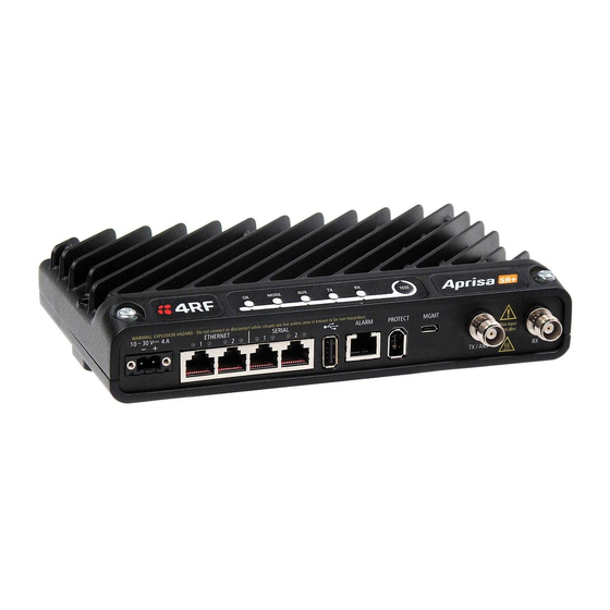
Product Options | 17 Product Options Interface Ports The standard Aprisa SR+ provides multiple interface port options for combinations of Ethernet and RS-232 serial. The product shown below is the two Ethernet ports plus two RS-232 serial ports. Interface Port Option Part Number 4 Ethernet ports and no RS-232 serial ports APSQ-N400-SSC-HD-40-ETAA... -
Page 20: Protected Station
Part Description APSQ-R400-SSC-FD-22-ETAA 4RF SR+, PS, 400-470 MHz, SSC, Full Duplex, 2E2S, ET, AA The Aprisa SR+ Protected Station is comprised of an Aprisa SR+ Protection Switch and two standard Aprisa SR+ radios mounted in a 2U rack mounting chassis. -
Page 21: Switch Over
Product Options | 19 Switch Over The switch over to the standby radio can be initiated automatically, on fault detection, or manually via the Hardware Manual Lock switch on the Protection Switch or the Software Manual Lock from SuperVisor. Additionally, it is possible to switch over the radios remotely without visiting the station site, via the remote control connector on the front of the Protection Switch. -
Page 22: Data Driven Protected Station
Part Description APSQ-D400-SSC-FD-22-ETAA 4RF SR+, PD, 400-470 MHz, SSC, Full Duplex, 2E2S, ET, AA The Aprisa SR+ Data Driven Protected Station shown is comprised of two standard Aprisa SR+ dual antenna port option radios and two external duplexers mounted on 19" rack mounting shelves (as shown above). -
Page 23: Specifications
Specifications | 21 Specifications RF Specifications ETSI Compliant Frequency Bands Broadcast Band Frequency Band Frequency Tuning Synthesizer Step Range Size 300 MHz 330-400 MHz 6.250 kHz 400 MHz 400-470 MHz 6.250 kHz 900 MHz 928-960 MHz 6.250 kHz Channel Sizes Channel Size Gross Radio Capacity 64 QAM... -
Page 24: Transmitter
22 | Specifications Transmitter Average Power output 64 QAM 0.01 to 1.25 W (+10 to +34 dBm, in 1 dB steps) Note: The Peak Envelope Power 16 QAM 0.01 to 2.5 W (+10 to +35 dBm, in 1 dB steps) (PEP) at maximum set power QPSK 0.01 to 5.0 W (+10 to +37 dBm, in 1 dB steps) - Page 25 Specifications | 23 Maintenance > Test Mode TRANSMITTER PRBS Test Enabled When active, the transmitter outputs a continuous PRBS signal. This can be used for evaluating the output spectrum of the transmitter and verifying adjacent channel power and spurious emission products. Deviation Test Enabled When active, the transmitter outputs a sideband tone at the deviation frequency used by the CPFSK modulator.
-
Page 26: Receiver
24 | Specifications Receiver 12.5 kHz 25 kHz Receiver sensitivity BER < 10 4-CPFSK –115 dBm –112 dBm BER < 10 QPSK –115 dBm –112 dBm BER < 10 16 QAM –109 dBm –106 dBm BER < 10 64 QAM –103 dBm –99 dBm BER <... -
Page 27: Interface Specifications
Specifications | 25 Interface Specifications Ethernet Interface The Aprisa SR+ radio features an integrated 10Base-T/100Base-TX layer-2 Ethernet switch. To simplify network setup, each port supports auto-negotiation and auto-sensing MDI/MDIX. Operators can select from the following preset modes: Auto negotiate 10Base-T half or full duplex 100Base-TX half or full duplex The switch is IEEE 802.3-compatible. -
Page 28: Protection Switch Specifications
26 | Specifications Protection Switch Specifications RF Insertion Loss < 0.5 dB Remote Control inputs Logic 4700 ohms pullup to +3.3 VDC Aprisa SR+ Product Description... -
Page 29: Power Specifications
Specifications | 27 Power Specifications Power Supply Aprisa SR+ Radio Nominal voltage +13.8 VDC (negative earth) Input voltage range +10 to +30 VDC Maximum power input 30 W Connector Molex 2 pin male screw fitting 39526-4002 Aprisa SR+ Protected Station Nominal voltage +13.8 VDC (negative earth) Input voltage range... -
Page 30: Power Dissipation
28 | Specifications Power Dissipation Aprisa SR+ Radio Transmit Power Power Dissipation (10 W radio with 4-CPFSK modulation) 10 W transmit power < 25 W 1 W transmit power < 24 W Aprisa SR+ Protected Station and Aprisa SR+ Data Driven Protected Station Transmit Power Power Dissipation (10 W radios with 4-CPFSK modulation) -
Page 31: General Specifications
Specifications | 29 General Specifications Environmental Operating temperature range -40 to +70˚ C Storage temperature range -40 to +80˚ C Operating humidity Maximum 95% non-condensing Acoustic noise emission No audible noise emission Mechanical Aprisa SR+ Radio Dimensions Width 210 mm Depth 130 mm (146 mm with TNC connectors) -
Page 33: Management
Management | 31 Management SuperVisor The Aprisa SR+ contains an embedded web server application (SuperVisor) to enable element management with any major web browser (such as Mozilla Firefox, Microsoft® Internet Explorer). SuperVisor enables operators to configure and manage the Aprisa SR+ base station radio and repeater / remote station radios over the radio link. -
Page 34: Viewing The Aprisa Sr+ Terminal Settings
32 | Management Viewing the Aprisa SR+ Terminal Settings The SuperVisor software enables operators to view the terminal settings: Aprisa SR+ Product Description... -
Page 35: Configuring The Aprisa Sr+ Terminal Details
Management | 33 Configuring the Aprisa SR+ Terminal Details The SuperVisor software enables operators to set the terminal details including: Terminal Name Location Contact Name Contact Details Current Date Configuring the Aprisa SR+ RF Network Details The SuperVisor software enables operators to set the RF Network Details including: –... -
Page 36: Configuring The Aprisa Sr+ Radio Settings
34 | Management Configuring the Aprisa SR+ Radio Settings The SuperVisor software enables operators to set the radio settings including: – sets the Transmit frequency in MHz TX Frequency – sets the Transmit Power in dBm TX Power – sets the Receive frequency in MHz RX Frequency - sets the Modulation Type QPSK to 64 QAM Modulation Type... -
Page 37: Command Line Interface
Management | 35 Command Line Interface The Aprisa SR+ has a Command Line Interface (CLI) which provides basic product setup and configuration. This interface can be accessed via an Ethernet Port (RJ-45) or the Management Port (USB micro type B). The Terminal menu is shown in the following picture: SNMP In addition to web-based management (SuperVisor) and the Command Line Interface, the Aprisa SR... -
Page 38: Led Display Panel
36 | Management LED Display Panel The Aprisa SR+ has an LED Display panel which provides on-site alarms / diagnostics without the need for Normal Operation In normal radio operation, the LEDs indicate the following conditions: MODE Solid Alarm present TX path fail RX path fail with severity... -
Page 39: Single Radio Software Upgrade
Management | 37 Single Radio Software Upgrade During a radio software upgrade, the LEDs indicate the following conditions: Software upgrade started - the OK LED flashes orange Software upgrade progress indicated by running RX to OK LEDs Software upgrade completed successfully - the OK LED solid orange Software upgrade failed - any LED flashing red during the upgrade Network Software Upgrade During a network software upgrade, the AUX LED flashes orange on the base station and all remote... -
Page 40: Applications
38 | Applications Applications This section describes sample Aprisa SR+ radio applications. The following applications are described: Basic point-to-multipoint application Advanced point-to-multipoint application with repeaters Multi-interface point-to-multipoint application Basic point-to-multipoint application Single base station with Ethernet SCADA data inputs to multiple geographically remote sites with Ethernet RTUs requiring control and data acquisition. -
Page 41: Advanced Point-To-Multipoint Application With Repeater
Applications | 39 Advanced point-to-multipoint application with repeater Single base station with Ethernet SCADA data inputs to multiple geographically remote sites with Ethernet RTUs requiring control and data acquisition. A repeater is deployed to service remote sites beyond the reach of the base station. The base station receives Ethernet frames from the SCADA server LAN and broadcasts all Ethernet frames to the repeater and its remote stations. -
Page 42: Multi-Interface Point-To-Multipoint Application
40 | Applications Multi-interface point-to-multipoint application Single base station with Ethernet and RS-232 SCADA data inputs to multiple geographically remote sites with Ethernet and RS-232 RTUs requiring control and data acquisition. The base station receives Ethernet / RS-232 frames from the SCADA servers and broadcasts all frames to all remote stations Each remote site receives Ethernet / RS-232 frames from the RTU and unicasts over the air to the base station. -
Page 43: Architecture
Architecture | 41 Architecture Product Description There are three components to the wireless interface: the Physical Layer (PHY), the Data Link Layer (DLL) and the Network Layer. These three layers are required to transport data across the wireless channel in the Point-to-Multipoint (PMP) configuration. -
Page 44: Hop By Hop Transmission
42 | Architecture Access Request This scheme is particularly suited to digital SCADA systems where all data flows through the base station. In this case it is important that the base station has contention-free access as it is involved in every transaction. -
Page 45: Network Layer
Architecture | 43 Network Layer Packet Routing Packet routing is realized in the Aprisa SR+ by adding a network address header to the packet. This contains source and destination addresses. For the Network Layer, there are 2 addresses, the address of the originating radio and the address of the terminating radio (i.e. -
Page 46: Security
44 | Architecture Security The Aprisa SR+ provides security features to implement the key recommendations for industrial control systems. The security provided builds upon the best in class from multiple standards bodies, including: IEC/TR 62443 (TC65) ‘Industrial Communications Networks – Network and System Security’ IEC/TS 62351 (TC57) ‘Power System Control and Associated Communications –... -
Page 47: Product Architecture
Architecture | 45 Product Architecture The following are the key components of the Aprisa SR+ design: Dual high performance ΣΔ fractional-N synthesizers to allow for full duplex operation 2x output frequency VCO for minimal pulling during transmit Wideband design electronically tunes over entire band Proven ultra low noise and spurious technology with over 50dB of SNR easily achieved Direct quadrature mixer with integrated Cartesian Feedback Loop The Cartesian Feedback Loop improves the efficiency and linearity of the entire transmitter chain... -
Page 48: Aprisa Sr+ Block Diagram
46 | Architecture Aprisa SR+ Block Diagram Aprisa SR+ Product Description... - Page 49 Contact Us | 47 Contact Us For further information or assistance, please contact Customer Support or your local 4RF representative. Our area representative contact details are available from our website: 4RF Limited 26 Glover Street, Ngauranga PO Box 13-506 Wellington 6032...
Need help?
Do you have a question about the Aprisa SR+ and is the answer not in the manual?
Questions and answers