4RF Aprisa SR+ User Manual
Smart, secure, industry-leading speed licensed point-to-multipoint scada communications for industrial monitoring and control
Hide thumbs
Also See for Aprisa SR+:
- User manual (492 pages) ,
- Product description (49 pages) ,
- Manual (12 pages)
Table of Contents
Advertisement
Quick Links
Advertisement
Table of Contents

Related Manuals for 4RF Aprisa SR+


Summary of Contents for 4RF Aprisa SR+
- Page 1 November 2015 Version 1.5.3...
- Page 3 Copyright © 2015 4RF Limited. All rights reserved. This document is protected by copyright belonging to 4RF Limited and may not be reproduced or republished in whole or part in any form without the prior written permission of 4RF Limited.
- Page 4 Changes or modifications not approved by the party responsible for compliance could void the user’s authority to operate the equipment. Equipment authorizations sought by 4RF are based on the Aprisa SR+ radio equipment being installed at a fixed restricted access location and operated in point-to-multipoint or point-to-point mode within the environmental profile defined by EN 300 019, Class 3.4.
- Page 5 Compliance Federal Communications Commission The Aprisa SR+ radio is designed to comply with the Federal Communications Commission (FCC) specifications as follows: Radio 47CFR part 24, part 90 and part 101 Private Land Mobile Radio Services 47CFR part 15 Radio Frequency Devices, EN 301 489 Parts 1 &...
- Page 6 Compliance Industry Canada The Aprisa SR+ radio is designed to comply with Industry Canada (IC) specifications as follows: Radio RSS-119 / RSS-134 This Class A digital apparatus complies with Canadian standard ICES-003. Cet appareil numérique de la classe A est conforme à la norme NMB-003 du Canada.
- Page 7 Compliance Hazardous Locations Notice This product is suitable for use in Class 1, Division 2, Groups A - D hazardous locations or non-hazardous locations. The following text is printed on the Aprisa SR+ fascia: WARNING: EXPLOSION HAZARD - Do not connect or disconnect while circuits are live unless area is known to be non-hazardous.
-
Page 8: Rf Exposure Warning
RF Exposure Warning WARNING: The installer and / or user of Aprisa SR+ radios shall ensure that a separation distance as given in the following table is maintained between the main axis of the terminal’s antenna and the body of the user or nearby persons. Minimum separation distances given are based on the maximum values of the following methodologies: 1. -
Page 9: Table Of Contents
Aprisa SR+ CD Contents ..............16 Software ................16 Documentation ..............16 About the Radio ............... 17 The 4RF Aprisa SR+ Radio ..............17 Product Overview ................18 Network Coverage and Capacity ............18 Automatic Registration ..............18 Remote Messaging ................ 18 Store and Forward Repeater ............ - Page 10 8 | Contents Front Panel Connections ............... 41 LED Display Panel ................42 Normal Operation ................ 42 Single Radio Software Upgrade ............43 Network Software Upgrade ............. 43 Test Mode ................. 44 Network Management ................45 Hardware Alarm Inputs / Outputs ............46 Alarm Input to SNMP Trap ...............
- Page 11 Contents | 9 Managing the Radio ..............67 SuperVisor ..................67 PC Requirements for SuperVisor ............68 Connecting to SuperVisor ............... 69 Management PC Connection ............. 70 PC Settings for SuperVisor ............71 Login to SuperVisor..............75 Logout of SuperVisor .............. 76 SuperVisor Page Layout ............
- Page 12 10 | Contents Product Options ..............324 Data Interface Ports ................324 Full Duplex Base Station ..............324 Protected Station ................325 Protected Ports ................. 326 Operation ................326 Switch Over ..............326 Switching Criteria ............... 327 Monitored Alarms ..............328 Configuration Management ............
- Page 13 Contents | 11 10. Maintenance ................359 No User-Serviceable Components ............359 Software Upgrade ................360 Network Software Upgrade ............360 Non-Protected Network Upgrade Process ........360 Protected Network Upgrade Process ......... 362 Single Radio Software Upgrade ............364 File Transfer Method ............364 USB Boot Upgrade Method .............
- Page 14 12 | Contents 14. Product End Of Life ..............397 End-of-Life Recycling Programme (WEEE) ..........397 The WEEE Symbol Explained ............397 WEEE Must Be Collected Separately ..........397 YOUR ROLE in the Recovery of WEEE ..........397 EEE Waste Impacts the Environment and Health ........397 15.
-
Page 15: Getting Started
Getting Started | 13 Getting Started This section is an overview of the steps required to commission an Aprisa SR+ radio network in the field: Phase 1: Pre-installation Confirm path planning. Page 52 Ensure that the site preparation is complete: Page 55 ... - Page 16 14 | Getting Started Phase 3: Establishing the link If radio’s IP address is not the default IP address (169.254.50.10 with a subnet Page 317 mask of 255.255.0.0) and you don’t know the radio’s IP address see ‘Command Line Interface’ on page 317. Connect the Ethernet cable between the radio’s Ethernet port and the PC.
-
Page 17: Introduction
Contact Us If you experience any difficulty installing or using Aprisa SR+ after reading this manual, please contact Customer Support or your local 4RF representative. Our area representative contact details are available from our website: 4RF Limited... -
Page 18: Aprisa Sr+ Accessory Kit
16 | Introduction Aprisa SR+ Accessory Kit The accessory kit contains the following items: Aprisa SR+ Quick Start Guide Aprisa SR+ CD Management Cable USB Cable USB A to USB micro B, 1m Aprisa SR+ CD Contents The Aprisa SR+ CD contains the following: Software ... -
Page 19: About The Radio
About the Radio The 4RF Aprisa SR+ Radio The 4RF Aprisa SR+ is a point-to-multipoint digital radio providing secure narrowband wireless data connectivity for SCADA, infrastructure and telemetry applications. The radios carry a combination of serial data and Ethernet data between the base station, repeater stations and remote stations. -
Page 20: Product Overview
18 | About the Radio Product Overview Network Coverage and Capacity The Aprisa SR+ has a typical link range of up to 120 km, however, geographic features, such as hills, mountains, trees and foliage, or other path obstructions, such as buildings, will limit radio coverage. Additionally, geography may reduce network capacity at the edge of the network where errors may occur and require retransmission. -
Page 21: Store And Forward Repeater
About the Radio | 19 Store and Forward Repeater The Aprisa SR+ in Repeater mode is used to link remote stations to the base station when direct communication is not possible due to terrain, distance, fade margin or other obstructions in the network. The following example depicts a repeater on the hill top to allow communication between the base station and the remote stations on the other side of hilly terrain. - Page 22 20 | About the Radio Multiple Repeater Single Hop The following example depicts an Aprisa SR+ multiple repeater single hop store and forward network supporting both overlapping and non-overlapping coverage repeater networks. An overlapped RF coverage area creates radio interference and might affect network performance and reduce throughput, as show in figure (a), where Remote 1 is in overlapped RF coverage with Repeater 1 and Repeater 2.
- Page 23 About the Radio | 21 Multiple Repeater Multiple Hop The following example depicts an Aprisa SR+ daisy chain multiple repeater multiple hop store and forward network i.e. multiple hops and multiple repeaters in non-overlapping RF coverage. The Aprisa SR+ daisy chain store and forward repeaters are currently supported in LBS MAC mode only.
-
Page 24: Repeater Messaging
22 | About the Radio Repeater Messaging The Aprisa SR+ uses a routed protocol throughout the network whereby messages contain source and destination addresses. The remote and repeater stations will register with a base station. In networks with a repeater, the repeater must register with the base station before the remotes can register with the base station. -
Page 25: Peer To Peer Communication Between Remote Radios
About the Radio | 23 Peer To Peer Communication Between Remote Radios The Aprisa SR+ peer to peer communication between remote radios is used to enable communication between remote radios via the repeater or base-repeater. It is useful if the SCADA server or base station fails or when in some industries like the water industry, where a reservoir remote station might send a direct message to a valve remote station to close or open the valve without the intervention of the SCADA server. -
Page 26: Product Features
SuperVisor web management support for element and sub-network (base-repeater-remotes) management SNMPv1/2/3 & encryption MIB supports for 4RF SNMP manager or third party SNMP agent network management SNMP context addressing for compressed SNMP access to remote stations ... -
Page 27: Security
About the Radio | 25 Build-configuration / flexibility of serial and Ethernet interface ports (3+1, 2+2, 4+0) Radio and user interface redundancy (provided with Aprisa SR+ Protected Station) Protected Station fully hot swappable and monitored hot standby ... -
Page 28: Performance
26 | About the Radio Performance Typical deployment of 30 remote stations from one base station with a practical limit of a few hundred remote stations Long distance operation High transmit power Low noise receiver Forward Error Correction ... -
Page 29: System Gain Vs Fec Coding
About the Radio | 27 System Gain vs FEC Coding This table shows the relationship between modulation, FEC coding, system gain, capacity and coverage. Maximum FEC coding results in the highest system gain, the best coverage but the least capacity ... -
Page 30: Architecture
28 | About the Radio Architecture The Aprisa SR+ Architecture is based around a layered TCP/IP protocol stack: Physical Proprietary wireless RS-232 and Ethernet interfaces Link Proprietary wireless (channel access, ARQ, segmentation) VLAN aware Ethernet bridge Network Standard IP Proprietary automatic radio routing table population algorithm ... -
Page 31: Data Link Layer / Mac Layer
About the Radio | 29 Data Link Layer / MAC layer The Aprisa SR+ PHY enables multiple users to be able to share a single wireless channel; however a DLL is required to manage data transport. The two key components to the DLL are channel access and hop by hop transmission. -
Page 32: Hop By Hop Transmission
30 | About the Radio Listen Before Send The Listen Before Send channel access scheme is realized using Carrier Sense Multiple Access (CSMA). In this mode, a pending transmission requires the channel to be clear. This is determined by monitoring the channel for other signals for a set time prior to transmission. -
Page 33: Network Layer
About the Radio | 31 Network Layer Packet Routing Aprisa SR+ is a standard static IP router which routes and forwards IP packet based on standard IP address and routing table decisions. Aprisa SR+ router mode (see figure below), enables the routing of IP packets within the Aprisa SR+ wireless network and in and out to the external router / IP RTUs devices connected to the Aprisa SR+ wired Ethernet ports. -
Page 34: Static Ip Router
32 | About the Radio Static IP Router The Aprisa SR+ works in the point-to-multipoint (PMP) network as a standard static IP router with the Ethernet and wireless / radio as interfaces and serial ports using terminal server as a virtual interface. The Aprisa SR+ static router is semi-automated operation, where the routing table is automatically created in the base station and populated with routes to all remotes and repeater stations in the network during the registration process and vice versa, where the routing table is automatically created in remote... - Page 35 About the Radio | 33 The Radio Network as a Gateway Router The Aprisa SR+ point-to-multipoint radio network can be considered as a gateway router where the ‘network Ethernet interface’ on each radio in the network is the ‘router port’. The routing table for all directly attached devices to the Aprisa SR+ network, at the Base or the Remote stations is automatically built and no static routes are required to be entered for those device routes.
- Page 36 34 | About the Radio Static IP Router – Human Error Free To ensure correct operation, the Aprisa SR+ router base station alerts when one (or more) of the devices is not configured for router mode or a duplicated IP is detected when manually added. When the user changes the base station IP address / subnet, the base station sends an ARP unsolicited announcement message and the remotes / repeaters auto-update their routing table accordingly.
-
Page 37: Bridge Mode With Vlan Aware
About the Radio | 35 Bridge Mode with VLAN Aware Ethernet VLAN Bridge / Switch Overview The Aprisa SR+ in Bridge mode of operation is a standard Ethernet Bridge based on IEEE 802.1d or VLAN Bridge based on IEEE 802.1q/p which forward / switch Ethernet packet based on standard MAC addresses and VLANs using FDB (forwarding database) table decisions. -
Page 38: Vlan Bridge Mode Description
36 | About the Radio VLAN Bridge Mode Description General – Aprisa SR+ VLAN Bridge The Aprisa SR+ works in a point-to-multipoint (PMP) network as a standard VLAN bridge with the Ethernet and wireless / radio as interfaces and serial ports using terminal server as a virtual interface. The Aprisa SR+ is a standard IEEE 802.1q VLAN bridge, where the FDB table is created by the bridge learning / aging process. - Page 39 About the Radio | 37 VLANs – Single, Double and Trunk VLAN ports The Aprisa SR+ supports single VLAN (CVLAN), double VLAN (SVLAN) and trunk VLAN. A single VLAN can be used to segregate traffic type. A double VLAN can be used to distinguish between Aprisa SR+ sub-networks (base-repeater-remote), where the outer SVLAN is used to identify the sub-network and the CVLAN is used to identify the traffic type.
-
Page 40: Avoiding Narrow Band Radio Traffic Overloading
38 | About the Radio Avoiding Narrow Band Radio Traffic Overloading The Aprisa SR+ supports mechanisms to prevent narrowband radio network overload: L3/L4 Filtering The L3 filtering can be used to block undesired traffic from being transferred on the narrow band channel, occupying the channel and risking the SCADA critical traffic. - Page 41 About the Radio | 39 Ethernet Data and Management Priority and Background Bulk Data Transfer Rate Alternatively to VLAN priority, users can control the Ethernet traffic priority (vs serial), management priority and rate in order to control the traffic load of the radio network, where important and high priority data (SCADA) will pass-through first assuring SCADA network operation.
-
Page 42: Interfaces
40 | About the Radio Interfaces Antenna Interface 2 x TNC, 50 ohm, female connectors Single or dual antenna ports (with or without the use of external duplexer / filter) Ethernet Interface 2, 3 or 4 ports 10/100 base-T Ethernet layer 2 switch using RJ45 Used for Ethernet user traffic and radio sub-network management. -
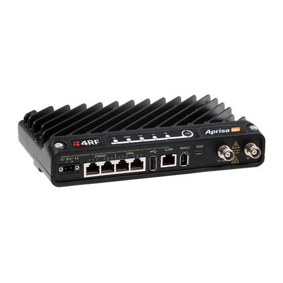
Page 43: Front Panel Connections
About the Radio | 41 Front Panel Connections Example; 2 Ethernet ports and 2 RS-232 serial ports - see ‘Data Interface Ports’ on page 324 for the other interface port options. Interface Port Option Part Number 2 Ethernet ports and 2 RS-232 serial ports APSQ-N400-SSC-HD-22-ENAA All connections to the radio are made on the front panel. -
Page 44: Led Display Panel
42 | About the Radio LED Display Panel The Aprisa SR+ has an LED Display panel which provides on-site alarms / diagnostics without the need for Normal Operation In normal radio operation, the LEDs indicate the following conditions: MODE Flashing Radio has not registered Alarm present... -
Page 45: Single Radio Software Upgrade
About the Radio | 43 Single Radio Software Upgrade During a radio software upgrade, the LEDs indicate the following conditions: Software upgrade started - the OK LED flashes orange Software upgrade progress indicated by running AUX to MODE LEDs ... -
Page 46: Test Mode
44 | About the Radio Test Mode Remote station and repeater station radios have a Test Mode which presents a real time visual display of the RSSI on the LED Display panel. This can be used to adjust the antenna for optimum signal strength (see ‘Maintenance >... -
Page 47: Network Management
About the Radio | 45 Network Management The Aprisa SR+ contains an embedded web server application (SuperVisor) to enable element management with any major web browser (such as Mozilla Firefox or Microsoft® Internet Explorer). SuperVisor enables operators to configure and manage the Aprisa SR+ base station radio and repeater / remote station radios over the radio link. -
Page 48: Hardware Alarm Inputs / Outputs
46 | About the Radio Hardware Alarm Inputs / Outputs The Aprisa SR+ provides two hardware alarm inputs to generate alarm events in the network and two hardware alarm outputs to receive alarm events from the network. The hardware alarm inputs and outputs are part of the event system. All alarm events can be viewed in SuperVisor event history log (see ‘Events >... -
Page 49: Implementing The Network
Implementing the Network | 47 Implementing the Network Network Topologies The following are examples of typical network topologies: Point-To-Point Network Point-to-Multipoint Network Point-to-Multipoint with Repeater 1 Point-to-Multipoint with Repeater 2 Aprisa SR+ User Manual 1.5.3... -
Page 50: Initial Network Deployment
48 | Implementing the Network Initial Network Deployment Install the Base Station To install the base station in your network: 1. Install the base station radio (see ‘Installing the Radio’ on page 58). 2. Set the radio Network ID to a unique ID in your entire network (see ‘Terminal > Device’ on page 88). 3. -
Page 51: Network Changes
Implementing the Network | 49 Network Changes Adding a Repeater Station To add a repeater station to your network: 1. Install the repeater station radio (see ‘Installing the Radio’ on page 58). 2. Set the radio Network ID to the same ID as the other stations in the network (see ‘Terminal > Device’ on page 88). -
Page 53: Preparation
Preparation | 51 Preparation Bench Setup Before installing the links in the field, it is recommended that you bench-test the links. A suggested setup for basic bench testing is shown below: When setting up the equipment for bench testing, note the following: Earthing Each radio should be earthed at all times. -
Page 54: Path Planning
52 | Preparation Path Planning The following factors should be considered to achieve optimum path planning: Antenna Selection and Siting Coaxial Cable Selection Linking System Plan Antenna Selection and Siting Selecting and siting antennas are important considerations in your system design. The antenna choice for the site is determined primarily by the frequency of operation and the gain required to establish reliable links. -
Page 55: Remote Station
Preparation | 53 Remote station There are two main types of directional antenna that are commonly used for remote stations, Yagi and corner reflector antennas. Yagi Antennas Factor Explanation Frequency Often used in 350-600 MHz bands Gain Varies with size (typically 11 dBi to 16 dBi) Stackable gain increase 2 Yagi antennas (+ 2.8 dB) -
Page 56: Antenna Siting
54 | Preparation Corner Reflector Antennas Factor Explanation Frequency Often used in 330-960 MHz bands Gain Typically 12 dBi Size Range from 0.36 m to 0.75 m in length Front to back ratio High (typically 30 dB) Beamwidth Broad (up to 60°) Antenna Siting When siting antennas, consider the following points: A site with a clear line of sight to the remote radio is recommended. -
Page 57: Coaxial Feeder Cables
Preparation | 55 Coaxial Feeder Cables To ensure maximum performance, it is recommended that you use good quality low-loss coaxial cable for all feeder runs. When selecting a coaxial cable consider the following: Factor Effect Attenuation Short cables and larger diameter cables have less attenuation Cost Smaller diameter cables are cheaper Ease of installation... -
Page 58: Site Requirements
56 | Preparation Site Requirements Power Supply Ensure a suitable power supply is available for powering the radio. The nominal input voltage for a radio is +13.8 VDC (negative earth) with an input voltage range of +10 to +30 VDC. The maximum power input is 35 W. WARNING: Before connecting power to the radio, ensure that the radio is grounded via the negative terminal of the DC power connection. -
Page 59: Earthing And Lightning Protection
Preparation | 57 Earthing and Lightning Protection WARNING: Lightning can easily damage electronic equipment. To avoid this risk, install primary lightning protection devices on any interfaces that are reticulated in the local cable network. You should also install a coaxial surge suppressor on the radio antenna port. Feeder Earthing Earth the antenna tower, feeders and lightning protection devices in accordance with the appropriate local and national standards. -
Page 60: Installing The Radio
You must comply with the safety precautions in this manual or on the product itself. 4RF does not assume any liability for failure to comply with these precautions. Mounting The Aprisa SR+ has four threaded holes (M4) in the enclosure base and two holes (5.2 mm) through the enclosure for mounting. -
Page 61: Din Rail Mounting
Part Description APSB-MBRK-DIN 4RF SR+ Acc, Mounting, Bracket, DIN Rail The Aprisa SR+ is mounted into the DIN rail mounting bracket using the four M4 threaded holes in the Aprisa SR+ enclosure base. Four 8 mm M4 pan pozi machine screws are supplied with the bracket. -
Page 62: Rack Shelf Mounting
Part Number Part Description APSB-MR19-X1U 4RF SR+ Acc, Mounting, 19" Rack Mount Shelf, 1U WARNING: If the Aprisa SR+ is operated in an environment where the ambient temperature exceeds 50°C, the Aprisa SR+ convection air flow over the heat sinks must be considered. -
Page 63: Wall Mounting
Installing the Radio | 61 Wall Mounting The Aprisa SR+ can be mounted on a wall using the two holes through the enclosure (5.2 mm diameter). Typically, M5 screws longer than 35 mm would be used. Aprisa SR+ User Manual 1.5.3... -
Page 64: Installing The Antenna And Feeder Cable
62 | Installing the Radio Installing the Antenna and Feeder Cable Carefully mount the antenna following the antenna manufacturers’ instructions. Run feeder cable from the antenna to the radio location. Lightning protection must be incorporated into the antenna system (see ‘Earthing and Lightning Protection’... -
Page 65: Connecting The Power Supply
Wire your power source to power connector and plug the connector into the radio. The connector screws can be fastened to secure the connector. Spare Molex 2 pin female power connectors can be ordered from 4RF: Part Number Part Description... -
Page 66: Spare Fuses
64 | Installing the Radio Spare Fuses The Aprisa SR+ PBA contains two fuses in the power input with designators F1 and F2. Both the positive and negative power connections are fused. The fuse type is a Littelfuse 0454007 with a rating of 7 A, 75 V, very fast acting. -
Page 67: Additional Spare Fuses
Additional Spare Fuses Additional spare fuses can be ordered from 4RF: Part Number Part Description APST-FNAN-454-07-02 4RF SR+ Spare, Fuse, Nano SMF, 454 Series, 7A, 2 items Aprisa SR+ User Manual 1.5.3... -
Page 69: Managing The Radio
Managing the Radio | 67 Managing the Radio SuperVisor The Aprisa SR+ contains an embedded web server application (SuperVisor) to enable element management with any major web browser (such as Mozilla Firefox or Microsoft® Internet Explorer). SuperVisor enables operators to configure and manage the Aprisa SR+ base station radio and repeater / remote station radios over the radio link. -
Page 70: Pc Requirements For Supervisor
1 GB Ram Pentium 4 and above (4RF does not support retina displays) Note: 4RF does not support Google Chrome, Opera browser or Apple Safari but when they have been used they have worked correctly. Aprisa SR+ User Manual 1.5.3... -
Page 71: Connecting To Supervisor
Managing the Radio | 69 Connecting to SuperVisor The predominant management connection to the Aprisa SR+ radio is with an Ethernet interface using standard IP networking. There should be only one Ethernet connection from the base station to the management network. The Aprisa SR+ has a factory default IP address of 169.254.50.10 with a subnet mask of 255.255.0.0. -
Page 72: Management Pc Connection
70 | Managing the Radio Management PC Connection The active management PC must only have one connection to the network as shown by path . There should not be any alternate path that the active management PC can use via an alternate router or alternate LAN that would allow the management traffic to be looped as shown by path . -
Page 73: Pc Settings For Supervisor
Managing the Radio | 71 PC Settings for SuperVisor To change the PC IP address: If your PC has previously been used for other applications, you may need to change the IP address and the subnet mask settings. You will require Administrator rights on your PC to change these. Windows XP example: 1. - Page 74 72 | Managing the Radio To change the PC connection type: If your PC has previously been used with Dial-up connections, you may need to change your PC Internet Connection setting to ‘Never dial a connection’. Windows Internet Explorer 8 example: 1.
- Page 75 Managing the Radio | 73 To change the PC pop-up status: Some functions within SuperVisor require Pop-ups enabled e.g. saving a MIB Windows Internet Explorer 8 example: 1. Open Internet Explorer. 2. Open the menu item Tools > Internet Options and click on the ‘Privacy’ tab. 3.
- Page 76 74 | Managing the Radio To enable JavaScript in the web browser: Some functions within SuperVisor require JavaScript in the web browser to be enabled. Windows Internet Explorer 8 example: 1. Open Internet Explorer. 2. Open the menu item Tools > Internet Options and click on the ‘Security’ tab. 3.
-
Page 77: Login To Supervisor
It is safe to ignore the warning and continue. The valid certificate is ‘Issued By: 4RF-APRISA’ which can be viewed in the browser. 2. Login with the Username and Password assigned to you. -
Page 78: Logout Of Supervisor
76 | Managing the Radio If the login is successful, the opening page will be displayed. If there is more than one user logged into the same radio, the Multiple Management Sessions popup will show the usernames and IP addresses of the users. This popup message will display until 5 seconds after the cursor is moved. -
Page 79: Supervisor Page Layout
Managing the Radio | 77 SuperVisor Page Layout Standard Radio The following shows the components of the SuperVisor page layout for a standard radio: SuperVisor Branding Bar The branding bar at the top of the SuperVisor frame shows the branding of SuperVisor on the left and the product branding on the right. - Page 80 78 | Managing the Radio SuperVisor Summary Bar The summary bar at the bottom of the page shows: Position Function Left Busy - SuperVisor is busy retrieving data from the radio that SuperVisor is logged into. Ready - SuperVisor is ready to manage the radio. Middle Displays the name of the radio terminal that SuperVisor is currently managing.
-
Page 81: Supervisor Menu
Managing the Radio | 79 SuperVisor Menu The following is a list of SuperVisor top level menu items: Local Terminal Network Network Table Terminal Summary Radio Exceptions Serial View Ethernet Security Maintenance Events Software Monitoring SuperVisor Parameter Settings Changes to parameters settings have no effect until the ‘Save’ button is clicked. Click the ‘Save’... -
Page 82: Supervisor Menu Access
80 | Managing the Radio SuperVisor Menu Access The SuperVisor menu has varying access levels dependent on the login User Privileges. The following is a list of all possible SuperVisor menu items versus user privileges: Terminal Settings Menu Items Menu Item View Technician Engineer... - Page 83 Managing the Radio | 81 Menu Item View Technician Engineer Admin Maintenance > Protection No Access Read-Write Read-Write Read-Write Maintenance > Licence No Access No Access Read-Write Read-Write Maintenance > SCADA No Access No Access Read-Write Read-Write Maintenance > MMS No Access No Access Read-Write...
-
Page 84: Supervisor Menu Items
82 | Managing the Radio SuperVisor Menu Items As SuperVisor screens are dependent on the Aprisa SR+ configuration deployed, the following section is split into two sections: Standard Radio Protected Station All SuperVisor menu item descriptions assume full access ‘Admin’ user privileges: Aprisa SR+ User Manual 1.5.3... -
Page 85: Standard Radio
Managing the Radio | 83 Standard Radio Terminal Terminal > Summary TERMINAL SUMMARY This page displays the current settings for the Terminal parameters. See ‘Terminal > Details’ on page 86, ‘Terminal > Device’ on page 88 and ‘Terminal > Operating Mode’ on page 94 for setting details. OPERATING SUMMARY Operating Mode This parameter displays the current Operating Mode i.e. - Page 86 84 | Managing the Radio TX Frequency (MHz) This parameter displays the current Transmit Frequency in MHz. TX Power (dBm) This parameter displays the current Transmit Power in dBm. RX Frequency (MHz) This parameter displays the current Receive Frequency in MHz. Channel Size (kHz) This parameter displays the current Channel Size in kHz.
- Page 87 Managing the Radio | 85 Repeater Network Segment ID This parameter identifies a repeater network segment and its associated remotes. In an overlapping coverage network where remote radios can ‘see’ multiple repeaters, it’s especially important to set different values for each repeater network segment and its associated remotes, so the associated remotes will communicate only with the appropriate repeater.
- Page 88 86 | Managing the Radio Terminal > Details MANUFACTURING DETAILS Radio Serial Number This parameter displays the Serial Number of the radio (shown on the enclosure label). Sub-Assembly Serial Number This parameter displays the Serial Number of the printed circuit board assembly (shown on the PCB label). Aprisa SR+ User Manual 1.5.3...
- Page 89 Managing the Radio | 87 HW Frequency Band This parameter displays the hardware radio frequency operating range. HW Type This parameter displays the hardware board assembly type. Radio MAC Address This parameter displays the MAC address of the radio (the management Ethernet MAC address). Active Software Version This parameter displays the version of the software currently operating the radio.
- Page 90 1. Enter the Terminal Name. 2. Enter the Location of the radio. 3. Enter a Contact Name. The default value is ‘4RF Limited’. 4. Enter the Contact Details. The default value is ‘support@4RF.com’. Aprisa SR+ User Manual 1.5.3...
- Page 91 Managing the Radio | 89 RF NETWORK DETAILS Network ID This parameter sets the network ID of this base station node and its remote / repeater stations in the network. The entry is four hexadecimal chars (not case sensitive). The default setting is CAFE. Base Station ID This parameter identifies the base station.
- Page 92 90 | Managing the Radio This parameter is set in remote stations to indicate the proximity of repeaters in the network when the Network Radius is set to 1. Option Function No Repeater Use when there are no repeaters in the network. Base Repeater Use when there is a base-repeater in the network.
- Page 93 Managing the Radio | 91 REGION SETTINGS Time Format This parameter sets the time format for all time based results. The default setting is 24 Hours. Date Format This parameter sets the date format for date based results. The default setting is DD/MM/YYYY. Measurement System This parameter sets the unit type for parameters like temperature readings.
- Page 94 92 | Managing the Radio Terminal > Date / Time TERMINAL DATE AND TIME Sets the Time and Date. This information is controlled from a software clock. Date and Time Synchronization This Date and Time Synchronization feature allows a radio to synchronize its date and time from an SNTP server.
- Page 95 Managing the Radio | 93 Auto Synchronization Period (s) This parameter sets the number of seconds between the end of the last synchronization and the next synchronization attempt. The minimum period is 60 seconds. A period of 0 seconds will disable synchronization attempts.
- Page 96 94 | Managing the Radio Terminal > Operating Mode OPERATING MODES Terminal Operating Mode The Terminal Operating Mode can be set to Base, Base Repeater, Repeater or Remote station. The default setting is Remote. Option Function Base The base station manages all traffic activity between itself, repeaters and remotes.
- Page 97 Managing the Radio | 95 SR Compatible The SR Compatible option enables over-the–air point-to-multipoint interoperation between an Aprisa SR+ network and New Aprisa SR radios. The default setting is unticked. When the Aprisa SR+ ‘SR Compatible’ option is activated, the Aprisa SR+ locks its modulation to QPSK (as per the New Aprisa SR modulation) and disables functionality which is not available in New Aprisa SR for full compatibility / interoperability operation.
- Page 98 96 | Managing the Radio TERMINAL PROTECTION Protection Type The Protection Type defines if a radio is a stand-alone radio or part of an Aprisa SR+ Protected Station. The default setting is None. Option Function None The SR+ radio is stand-alone radio (not part of an Aprisa SR+ Protected Station).
-
Page 99: Radio
Managing the Radio | 97 Radio Radio > Radio Summary This page displays the current settings for the Radio parameters. See ‘Radio > Radio Setup’ and ‘Radio > Channel Setup’ for setting details. Aprisa SR+ User Manual 1.5.3... - Page 100 98 | Managing the Radio Radio > Channel Summary This page displays the current settings for the Channel parameters. See ‘Radio > Channel Setup’ for setting details. DATA COMPRESSION IP Header Compression Ratio See ‘IP Header Compression Ratio’ on page 115. Payload Compression Ratio The payload is compressed using level 3 QuickLZ data compression.
- Page 101 Managing the Radio | 99 Radio > Radio Setup Transmit frequency, transmit power and channel size would normally be defined by a local regulatory body and licensed to a particular user. Refer to your site license details when setting these fields. TRANSMITTER / RECEIVER Important: 1.
- Page 102 100 | Managing the Radio Single Frequency Operation The TX and RX frequencies of the base station, repeater station and all the remote stations are on the same frequency. To change the TX and RX frequencies: 1. Change the TX and RX frequencies of the remote stations operating from the repeater station to the new frequency.
- Page 103 Managing the Radio | 101 Dual Frequency No Repeater The TX frequency of all the remote stations matches the RX frequency of the base station. The RX frequency of all the remote stations matches the TX frequency of the base station. To change the TX and RX frequencies: 1.
- Page 104 102 | Managing the Radio Dual Frequency with Repeater The TX frequency of the remote stations associated with the base station matches the RX frequency of the base station. The TX frequency of the repeater station associated with the base station matches the RX frequency of the base station.
- Page 105 Managing the Radio | 103 To change the TX and RX frequencies: 1. For all the remote stations operating from the repeater station, change the RX frequency to frequency A and the TX frequency to frequency B. The radio links to these remote stations will fail. 2.
- Page 106 104 | Managing the Radio GENERAL Channel Size (kHz) This parameter sets the Channel Size for the radio (see ‘Channel Sizes’ on page 378 for Radio Capacities). The default setting is 12.5 kHz. Antenna Port Configuration This parameter sets the Antenna Port Configuration for the radio. Option Function Single Antenna...
- Page 107 Managing the Radio | 105 MODEM The Radio > Radio Setup screen Modem section is different for a base / repeater / base-repeater station and a remote station. Modem Mode This parameter sets the Modem Mode in the radio. The Modem Mode option list is dependent on the radio Hardware Variant.
- Page 108 106 | Managing the Radio MODEM - Base / Repeater/ Base-Repeater Station Modulation Type The base to remote / repeater or repeater to remote / base direction of transmission is always fixed i.e. not adaptive. This parameter sets the fixed TX Modulation Type for the base / base-repeater / repeater radio. Option Function QPSK (High Gain)
- Page 109 Managing the Radio | 107 ACM Control This parameter enables / disables Adaptive Code Modulation for the remote to base direction of transmission (upstream). When ACM is enabled (ACM Control set to Standard or Fast), the base station sends a modulation type recommendation to each remote radio based on the signal quality for each individual remote radio.
- Page 110 108 | Managing the Radio ADAPTIVE CODING MODULATION These settings are only used if the ACM Control is set to Enabled and only apply to the base to remote direction of transmission (downstream). Modulation Range This parameter sets the upper limit of the range that the base station will recommend to the remote radios.
- Page 111 Managing the Radio | 109 ADAPTIVE CODING MODULATION These settings are only used if the Modulation Type is set to Adaptive and only apply to the remote to base / base-repeater / repeater direction of transmission (upstream). Default Modulation This parameter sets the default modulation and FEC code rate for the remote to base / base-repeater / repeater direction of transmission when the ACM mechanism fails for whatever reason.
- Page 112 110 | Managing the Radio Radio > Channel Setup CHANNEL SETTINGS Access Scheme This parameter sets the Media Access Control (MAC) used by the radio for over the air communication. Option Function Access Request Channel access scheme where the base station controls the communication on the channel.
- Page 113 Managing the Radio | 111 Listen Before Send Channel access scheme where network elements listen to ensure with the channel is clear, before trying to access the channel. This Acknowledgement mode is optimised for low load networks and repeated networks. With Acknowledgement, unicast requests from the remote station are acknowledged by the base station to ensure that the transmission has been successful.
- Page 114 112 | Managing the Radio Maximum Packet Size (Bytes) This parameter sets the maximum over-the-air packet size in bytes. A smaller maximum Packet Size is beneficial when many remote stations or repeater stations are trying to access the channel. The default setting is 1550 bytes.
- Page 115 Managing the Radio | 113 Serial Data Stream Mode This parameter controls the traffic flow in the radio serial ports. Option Function Broadcast Serial port traffic from the network is broadcast on all serial ports on this radio. This will include the RS-232 port derived from the USB port.
- Page 116 114 | Managing the Radio TRAFFIC SETTINGS Background Bulk Data Transfer Rate This parameter sets the data transfer rate for large amounts of management data. Option Function High Utilizes more of the available capacity for large amounts of management data. Highest impact on user traffic. Medium Utilizes a moderate of the available capacity for large amounts of management data.
- Page 117 Managing the Radio | 115 DATA COMPRESSION IP Header Compression Ratio The IP Header Compression implements TCP/IP ROHC v2 (Robust Header Compression v2. RFC4995, RFC5225, RFC4996) to compress the IP header. IP header compression allows for faster point-to-point transactions, but only in a star network. IP Header Compression module comprises of two main components, compressor and decompressor.
- Page 118 116 | Managing the Radio Radio > Advanced Setup This page is only visible when the Channel Setup > Network Traffic Type is set to User Defined. ADVANCED CHANNEL SETTINGS Default Packet Time to Live (ms) This parameter sets the default time a packet is allowed to live in the system before being dropped if it cannot be transmitted over the air.
- Page 119 Managing the Radio | 117 Serial Packet Time to Live (ms) This parameter sets the time a serial packet is allowed to live in the system before being dropped if it cannot be transmitted over the air. The default setting is 800 ms. Ethernet Packet Time to Live (ms) This parameter sets the time an Ethernet packet is allowed to live in the system before being dropped if it cannot be transmitted over the air.
-
Page 120: Serial
118 | Managing the Radio Serial Serial > Summary RS-232 Hardware Ports This page displays the current settings for the serial port parameters. Note: This screen is dependent on the Data Port product option purchased (see ‘Data Interface Ports’ on page 324). - Page 121 Managing the Radio | 119 USB Serial Ports This page displays the current settings for the USB serial port parameters. Type This parameter displays the Serial Port interface type. If the Name is USB Serial Port: Option Function RS-232 Indicates that a USB to RS-232 serial converter is plugged into the radio.
- Page 122 120 | Managing the Radio Serial > Port Setup RS-232 Hardware Ports This page provides the setup for the serial port settings. SERIAL PORTS SETTINGS Note: This screen is dependent on the Data Port product option purchased (see ‘Data Interface Ports’ on page 324).
- Page 123 Managing the Radio | 121 Mode This parameter defines the mode of operation of the serial port. The default setting is Standard. Option Function Disabled The serial port is not required. Standard The serial port is communicating with serial ports on other stations.
- Page 124 122 | Managing the Radio Flow Control This parameter sets the flow control of the serial port. The default setting is Disabled. Option Function None The Aprisa SR+ radio port (DCE) CTS is in a permanent ON (+ve) state. This does not go to OFF if the radio link fails. CTS-RTS CTS / RTS hardware flow control between the DTE and the Aprisa SR+ radio port (DCE) is enabled.
- Page 125 Managing the Radio | 123 Mirrored Bits® 4RF has introduced a channel access scheme optimized for Mirrored Bits® support between two devices. Error free transport of the protocol can be achieved through specific serial traffic configuration settings, which are dependent on the radio RF configuration, Mirrored Bits® devices and network characteristics.
- Page 126 124 | Managing the Radio Terminal Server This menu item is only applicable if the serial port has an operating mode of Terminal Server. The Terminal Server operating mode provides encapsulation of serial data into an IP packet (over TCP or UDP).
- Page 127 Managing the Radio | 125 Protocol This parameter sets the L4 TCP/IP or UDP/IP protocol used for terminal server operation. The default setting is TCP. Mode This parameter defines the mode of operation of the terminal server connection. The default setting is Client and Server.
- Page 128 126 | Managing the Radio Serial Line Interface Protocol (SLIP) This menu item is only applicable if the serial port has an operating mode of SLIP. The SLIP operating mode provides IP packet encapsulation over RS-232 serial interface as per the SLIP protocol RFC 1055.
- Page 129 Managing the Radio | 127 USB Serial Ports This page provides the setup for the USB serial port settings. SERIAL PORTS SETTINGS Mode This parameter defines the mode of operation of the serial port. The default setting is Disabled. Option Function Disabled The serial port is not required.
- Page 130 128 | Managing the Radio Character Length (bits) This parameter sets the character length to 7 or 8 bits. The default setting is 8 bits. Parity This parameter sets the parity to Even, Odd or None. The default setting is None. Stop Bits (bits) This parameter sets the number of stop bits to 1 or 2 bits.
-
Page 131: Ethernet
Managing the Radio | 129 Ethernet Ethernet > Summary This page displays the current settings for the Ethernet port parameters and the status of the ports. See ‘Ethernet > Port Setup’ for configuration options. Aprisa SR+ User Manual 1.5.3... - Page 132 130 | Managing the Radio Ethernet > Port Setup This page provides the setup for the Ethernet ports settings. ETHERNET PORT SETTINGS Note: This screen is dependent on the Data Port product option purchased (see ‘Data Interface Ports’ on page 324). The Data Port product option shown is a 2E2S – two Ethernet ports and two Serial ports Mode This parameter controls the Ethernet traffic flow.
- Page 133 Managing the Radio | 131 Speed (Mbit/s) This parameter controls the traffic rate of the Ethernet port. The default setting is Auto. Option Function Auto Provides auto selection of Ethernet Port Speed 10/100 Mbit/s The Ethernet Port Speed is manually set to 10 Mbit/s The Ethernet Port Speed is manually set to 100 Mbit/s Duplex This parameter controls the transmission mode of the Ethernet port.
- Page 134 132 | Managing the Radio Ethernet > L2 Filtering This page is only available if the Ethernet traffic option has been licensed (see ‘Maintenance > Licence’ on page 204). FILTER DETAILS L2 Filtering provides the ability to filter (white list) radio link user traffic based on specified Layer 2 MAC addresses.
- Page 135 Managing the Radio | 133 Protocol Type This parameter sets the EtherType accepted ARP, VLAN, IPv4, IPv6 or Any type. Example: In the screen shot, the rules are configured in the base station which controls the Ethernet traffic to the radio link.
- Page 136 134 | Managing the Radio Ethernet > VLAN This page is only available if the Ethernet traffic option has been licensed (see ‘Maintenance > Licence’ on page 204). VLAN PORT SETTINGS – All Ports This page specifies the parameters that relate to all Ethernet ports when working in Bridge Mode. Three parameters are global parameters for the Ethernet Bridge;...
- Page 137 Managing the Radio | 135 Double Tag Egress S-VLAN Priority This parameter sets the S-VLAN egress traffic priority. The default is Priority 1 (Best Effort). Option Egress Priority High / Low Classification Priority Priority 0 Background Lowest Priority Priority 1 (Best Effort) Priority 2 (Excellent Effort) Priority 3 (Critical Applications) Priority 4 (Video)
- Page 138 136 | Managing the Radio VLAN PORT SETTINGS – Port 1 This example is shown for the product option of 2E2S i.e. two Ethernet ports. PORT PARAMETERS Ingress Filtering Enabled This parameter enables ingress filtering. When enabled, if ingress VLAN ID is not included in its member set (inner tagged), the frame will be discarded.
- Page 139 Managing the Radio | 137 If double tagging is enabled on the port, incoming frames should always be double tagged. If the incoming frame is untagged, then the PVID (port VLAN ID) is used and forwarded with the Port Ingress priority provided the PVID is configured in the Port VLAN Membership of any of the Ethernet ports.
- Page 140 138 | Managing the Radio Egress Action This parameter sets the action taken on the frame on egress from the Ethernet port. The default is Untag and forward. Option Function Untag and forward Removes the tagged information and forwards the frame.
- Page 141 Managing the Radio | 139 IP > IP Summary > Bridge / Gateway Router Modes This page displays the current settings for the Networking IP Settings for an Ethernet Operating Mode of ‘Bridge’ or ‘Gateway Router’. See ‘IP > IP Setup > Bridge / Gateway Router Modes’ on page 141 for configuration options. Aprisa SR+ User Manual 1.5.3...
- Page 142 140 | Managing the Radio IP > IP Summary > Router Mode This page displays the current settings for the Networking IP Settings for an Ethernet Operating Mode of ‘Router’. See ‘IP > IP Setup > Router Mode’ on page 142 for configuration options. Aprisa SR+ User Manual 1.5.3...
- Page 143 Managing the Radio | 141 IP > IP Setup > Bridge / Gateway Router Modes This page provides the setup for the IP Settings for an Ethernet Operating Mode of ‘Bridge’ or ‘Gateway Router’. NETWORKING IP SETTINGS IP Address Set the static IP Address of the radio (Management and Ethernet ports) assigned by your site network administrator using the standard format xxx.xxx.xxx.xxx.
- Page 144 142 | Managing the Radio IP > IP Setup > Router Mode This page provides the setup for the IP Settings for and Ethernet Operating Mode of ‘Router’. PORT SETTINGS – port (n) Note: This screen is dependent on the Data Port product option purchased (see ‘Data Interface Ports’ on page 324).
- Page 145 Managing the Radio | 143 RADIO INTERFACE IP SETTINGS The RF interface IP address is the address that traffic is routed to for transport over the radio link. This IP address is only used when Router Mode is selected i.e. not used in Bridge Mode. Radio Interface IP Address Set the IP Address of the RF interface using the standard format xxx.xxx.xxx.xxx.
- Page 146 144 | Managing the Radio IP > L3 Filtering This page is only available if the Ethernet traffic option has been licensed (see ‘Maintenance > Licence’ on page 204) and Router Mode selected. It is not active in Bridge Mode (see 'Terminal > Operating Mode’ on page 94).
- Page 147 Managing the Radio | 145 Source Wildcard Mask This parameter defines the mask applied to the source IP address. 0 means that it must be a match. If the source wildcard mask is set to 0.0.0.0, the complete source IP address will be evaluated for the filter criteria.
- Page 148 146 | Managing the Radio IP > IP Routes This page is only available if the Ethernet traffic option has been licensed (see ‘Maintenance > Licence’ on page 204) and Router Mode selected. It is not valid for Bridge Mode (see 'Terminal > Operating Mode’ on page 94).
- Page 149 Managing the Radio | 147 Gateway Address This parameter sets the gateway address where packets will be forwarded to. If the gateway interface is set to Ethernet Ports, the gateway address is the IP address of the device connected to the Ethernet port. ...
-
Page 150: Qos
148 | Managing the Radio QoS > Summary This page provides a summary of the QoS Settings. See ‘QoS > Traffic Priority’ and ‘QoS > Traffic Classification’ for configuration options. Aprisa SR+ User Manual 1.5.3... - Page 151 Managing the Radio | 149 QoS > Traffic Priority TRAFFIC PRIORITY Default Management Data Priority The Default Management Data Priority controls the priority of the Ethernet management traffic relative to Ethernet customer traffic. It can be set to Very High, High, Medium and Low. The default setting is Medium.
- Page 152 150 | Managing the Radio ETHERNET PRIORITY This parameter controls the per port priority of the Ethernet customer traffic relative to the serial customer traffic. If equal priority is required to serial traffic, this setting must be the same as the Serial Data Priority setting.
- Page 153 Managing the Radio | 151 PRIORITY DEFINITIONS PCP (Priority Code Point) These settings provide priority translation / mapping between the external radio LAN VLAN priority network and the radio internal VLAN priority network, using the VLAN tagged PCP (Priority Code Point) priority field in the Ethernet/VLAN frame.
- Page 154 152 | Managing the Radio This is done by mapping the external radio network VLAN priority to the internal radio CoS / priority using the ‘PCP priority definition’ tab. The radio support 4 queues, thus at maximum an 8 -> 4 VLAN priority / CoS mapping is done.
- Page 155 Managing the Radio | 153 DSCP (Differentiated Services Code Point) These settings provide translation / mapping between the external radio IP priority network and the radio internal IP priority network, using the DSCP (DiffServ Code Point) priority field in the IP packet header. Differentiated Services (DiffServ) is a new model in which traffic is treated by routers with relative priorities based on the IPv4 type of services (ToS) field.
- Page 156 154 | Managing the Radio This is done by mapping the external radio network DSCP priority to the internal radio CoS / priority levels using the ‘DSCP priority definition’ tab. The radio support four queues, thus at maximum a 64 -> 4 CoS / priority mapping is done.
- Page 157 Managing the Radio | 155 QoS > Traffic Classification These settings provide multiple traffic classification profiles based on classification rules. Profiles for a specific traffic type, protocol or application can be assigned to a particular VLAN and CoS / priority in bridge mode or to CoS / priority in router mode to provide the appropriate QoS treatment.
- Page 158 156 | Managing the Radio Bridge Mode Traffic Classification Settings TRAFFIC CLASSIFICATION VLAN bridge mode traffic classification settings provide mapping / assigning of profiles (set by rules to match a specific traffic type) to a VLAN ID and VLAN CoS / priority. The profile which is used to match to a specific traffic type will be identified in the radio network by its associated VLAN ID and VLAN CoS / priority to provide the appropriate QoS treatment.
- Page 159 Managing the Radio | 157 Assigned VLAN ID Traffic packets that match the applied profile rules will be assigned to the selected ‘assigned VLAN ID’ setting of VLAN ID in the range of 0 to 4095. A VLAN ID of an ingress packet matching the classification rule (see ‘VLAN ID’ rule in next page) shall be changed to the ‘assigned VLAN ID’...
- Page 160 158 | Managing the Radio To edit a traffic classification, select the profile and click on the Edit button ETHERNET PORT CRITERIA Ethernet Port Set the layer 1 Ethernet port number or all Ethernet ports in the selected profile classification rule. VLAN ID Sets the layer 2 packet Ethernet header VLAD ID field in the selected profile classification rule.
- Page 161 Managing the Radio | 159 PRIORITY CRITERIA Priority Type Set the layer 2 Ethernet or layer 3 IP packet header priority type fields in the selected profile classification rules. Priority Type Description None Do not use any layer 2 / 3 Ethernet or IP header priority fields in the selected profile classification rules.
- Page 162 160 | Managing the Radio The following table shows the layer 3 packet IP header DSCP priority field values DSCP Value DSCP Priority (Decimal) EF (Expedited Forwarding) AF11 (Assured Forwarding) AF12 AF13 AF21 AF22 AF23 AF31 AF32 AF33 AF41 AF42 AF43 CS0/Best Effort (BE) CS1 (Class Selector )
- Page 163 Managing the Radio | 161 Click on More Options if more Layer 2/3/4 (Ethernet / IP / TCP or UDP) packet header fields are required for the selected profile classification rule. This page describes all the possible fields that can be used for the classification rules in bridge mode.
- Page 164 162 | Managing the Radio EtherType (Hex) This parameter sets the Layer 2 Ethernet packet header EtherType field in the selected profile classification rule. EtherType is a 16 bit (two octets) field in an Ethernet frame. It is used to indicate which protocol is encapsulated in the payload of an Ethernet Frame.
- Page 165 Managing the Radio | 163 IP Protocol Number This parameter sets the Layer 3 IP packet header ‘Protocol’ field in the selected profile classification rule. This field defines the protocol used in the data portion of the IP datagram. Protocol number Examples: Protocol Protocol value (decimal)
- Page 166 164 | Managing the Radio Router Mode Traffic Classification Settings TRAFFIC CLASSIFICATION Router Mode traffic classification settings provide mapping / assigning of profiles (set by rules to match a specific traffic type) to a CoS / priority. The profile which is used to match to a specific traffic type will be identified in the radio network by its associated CoS / priority to provide the appropriate QoS treatment.
- Page 167 Managing the Radio | 165 Controls The Save button saves all profiles to the radio. The Cancel button removes all changes since the last save or first view of the page if there has not been any saves. This button will un-select all the Select radio buttons. The Edit button will show the next screen for the selected profile where the profile can be configured.
- Page 168 166 | Managing the Radio To edit a traffic classification, select the profile and click on the Edit button ETHERNET PORT CRITERIA Ethernet Port Set the layer 1 Ethernet port number or all Ethernet ports in the selected profile classification rules. PRIORITY CRITERIA DSCP Range Sets the DSCP priority value/s field in the selected profile classification rule.
- Page 169 Managing the Radio | 167 The following table shows the layer 3 packet IP header DSCP priority field values DSCP Value DSCP Priority (Decimal) EF (Expedited Forwarding) AF11 (Assured Forwarding) AF12 AF13 AF21 AF22 AF23 AF31 AF32 AF33 AF41 AF42 AF43 CS0/Best Effort (BE) CS1 (Class Selector )
- Page 170 168 | Managing the Radio Click on More Options if more Layer 3/4 packet header fields are required for the selected profile classification rule. This page describes all the possible fields that can be used for the classification rules in router mode.
- Page 171 Managing the Radio | 169 Destination IP Wildcard Mask This parameter sets the wildcard mask applied to the ‘Destination IP Address’. This parameter is written in the standard IPv4 format of ‘xxx.xxx.xxx.xxx’. 0 means that it must be a match. If the wildcard mask is set to 0.0.0.0, the complete Destination IP Address will be evaluated for the classification rules.
-
Page 172: Security
170 | Managing the Radio Security Security > Summary This page displays the current settings for the Security parameters. See ‘Security > Setup’ and ‘Security > Manager’ for configuration options. Aprisa SR+ User Manual 1.5.3... - Page 173 Managing the Radio | 171 Security > Setup PAYLOAD SECURITY PROFILE SETTINGS Security Profile Name This parameter enables the user to predefine a security profile with a specified name. Security Scheme This parameter sets the security scheme to one of the values in the following table: Security Scheme Disabled (No encryption and no Message Authentication Code) AES Encryption + CCM Authentication 128 bit...
- Page 174 172 | Managing the Radio Payload Encryption Key Type This parameter sets the Payload Encryption Key Type: Option Function Pass Phrase Use the Pass Phrase password format for standard security. Raw Hexadecimal Use the Raw Hexadecimal key format for better security. It must comply with the specified encryption key size e.g.
- Page 175 USB Storage Detected A USB flash drive is plugged into the radio host port. Note: Some brands of USB flash drives may not work with 4RF radios. Controls The ‘Save’ button saves the Key Encryption Key settings to the radio. If the Security Level is set to Strong (see ‘Security Level’...
- Page 176 174 | Managing the Radio Key Encryption Key Summary The security of over-the-air-rekeying depends on a truly random Key Encryption Key. This is why the use of a Raw Hexadecimal key is recommended as a plain text phrase based on known spelling and grammar constructs is not very random.
- Page 177 Managing the Radio | 175 PROTOCOL SECURITY SETTINGS Telnet option This parameter option determines if you can manage the radio via a Telnet session. The default setting is disabled. ICMP option (Internet Control Message Protocol) This parameter option determines whether the radio will respond to a ping. The default setting is disabled.
- Page 178 176 | Managing the Radio SNMPv3 Authentication Passphrase The SNMPv3 Authentication Passphrase can be changed via the SNMPv3 secure management protocol interface (not via SuperVisor). When viewing / managing the details of the users via SNMPv3, the standard SNMP-USER-BASED-SM-MIB interface is used. This interface can be used to change the SNMPv3 Authentication Passphrase of the users. The SNMPv3 Authentication Passphrase of a user required to be changed cannot be changed by the same user i.e.
- Page 179 Managing the Radio | 177 Changing the desUserMD5 user encryption key / password from desUserMD5 to desUserMD5New: c:\usr\bin>snmpusm -v 3 -u desUserMD5 -n priv -l authPriv -a MD5 -A desUserMD5 -x DES -X desUserMD5 -Cx 172.17.70.17 passwd desUserMD5 desUserMD5New Changing the desUserMD5 user authentication key / password from desUserMD5 to desUserMD5New: c:\usr\bin>snmpusm -v 3 -u desUserMD5 -n priv -l authPriv -a MD5 -A desUserMD5 -x DES -X desUserMD5New -Ca 172.17.70.17 passwd desUserMD5 desUserMD5New...
- Page 180 178 | Managing the Radio Reset Unknown Passphrases with the Command Line Interface As it is not possible for users to read previously set passphrases, a CLI command is available from Aprisa SR+ software release 1.4.0 to ‘reset’ the SNMPv3 USM users back to defaults. Note: USM users are not related to CLI and SuperVisor users.
- Page 181 Managing the Radio | 179 SECURITY LEVEL SETTINGS Security Level This parameter sets the Security Level active security features. The default setting is Standard. Option Payload HTTPS SNMPv3 USB KEK Only Encryption Standard Strong If the Security Level is reduced, there will be a pop up message warning that Key Encryption Key will be reset to the default value.
- Page 182 180 | Managing the Radio Security > Users Note: You must login with ‘admin’ privileges to add, disable, delete a user or change a password. USER DETAILS Shows a list of the current users setup in the radio. ADD NEW USER To add a new user: 1.
- Page 183 Managing the Radio | 181 There are four pre-defined User Privilege settings to allocate access rights to users. These user privileges have associated default usernames and passwords of the same name. The default login is ‘admin’. This login has full access to all radio parameters including the ability to add and change users. There can only be a maximum of two usernames with admin privileges and the last username with admin privileges cannot be deleted.
- Page 184 182 | Managing the Radio Security > SNMP In addition to web-based management (SuperVisor), the network can also be managed using the Simple Network Management Protocol (SNMP) using any version of SNMP v1/2/3. MIB files are supplied, and these can be used by a dedicated SNMP Manager, such as Castle Rock’s SNMPc, to access most of the radio’s configurable parameters.
- Page 185 Managing the Radio | 183 SNMP Manager Setup The SNMP manager community strings must be setup to access the base station and remote / repeater stations. To access the base station, a community string must be setup on the SNMP manager the same as the community string setup on the radio (see ‘Security >...
- Page 186 184 | Managing the Radio Security > RADIUS This page displays the current settings for the Security RADIUS. RADIUS - Remote Authentication Dial In User Service RADIUS is a client / server system that secures the Aprisa SR+ radio network against unauthorized access. It is based on open standard RFCs: RFC 2865/6, 5607, 5080 and 2869.
- Page 187 Managing the Radio | 185 RADIUS AUTHENTICATION SETTINGS Authentication Mode This parameter sets the Authentication Mode. Option Function Local Authentication No radius Authentication – allows any local user privilege Radius Authentication Only radius Authentication – no local user privilege Radius Authentication Uses radius Authentication if it is available.
- Page 188 186 | Managing the Radio Maximum Retries Duration (MRD) (seconds) This parameter sets the maximum duration it will attempt retries when the server is not responding. Unknown Transaction Attributes This parameter sets the radio’s response to unknown attributes received from the radius server. Option Function Ignore and Authenticate...
- Page 189 Managing the Radio | 187 Security > Manager CURRENT PAYLOAD SECURITY PROFILE Profile Name This parameter shows the predefined security profile active on the radio. Status This parameter displays the status of the predefined security profile on the radio (always active). PREVIOUS PAYLOAD SECURITY PROFILE Profile Name This parameter displays the security profile that was active on the radio prior to the current profile being...
- Page 190 188 | Managing the Radio Activate This parameter activates the previous security profile (restores to previous version). PREDEFINED PAYLOAD SECURITY PROFILE Profile Name This parameter displays the new security profile that could be activated on the radio or distributed to all remote radios with Security >...
- Page 191 Managing the Radio | 189 Security > Distribution REMOTE PAYLOAD SECURITY PROFILE DISTRIBUTION Predefined Profile Name This parameter displays the predefined security profile available for distribution to remote stations. Status This parameter shows if a predefined security profile is available for distribution to remote stations. Option Function Unavailable...
- Page 192 190 | Managing the Radio To distribute the payload security profile to remote stations: This process assumes that a payload security profile has been setup (see ‘Security > Setup’ on page 171). 1. Tick Start Transfer and click Apply. Note: This process could take up to 1 minute per radio depending on channel size, Ethernet Management Priority setting and the amount of customer traffic on the network.
- Page 193 Managing the Radio | 191 REMOTE PAYLOAD SECURITY PROFILE ACTIVATION When the security profile has been distributed to all the remote stations, the security profile is then activated in all the remote stations with this command. The base station will always attempt to distribute the profile successfully. This broadcast distribution has its own retry mechanism.
-
Page 194: Maintenance
192 | Managing the Radio Maintenance Maintenance > Summary This page displays the current settings for the Maintenance parameters. DIAGNOSTICS Last RX Packet RSSI (dBm) This parameter displays the receiver RSSI reading taken from the last data packet received. Aprisa SR+ User Manual 1.5.3... - Page 195 Managing the Radio | 193 GENERAL Local Status Polling Period (sec) This parameter displays the rate at which SuperVisor refreshes the Local Radio alarm LED states and RSSI value. Remote Status Polling Period (sec) This parameter displays the rate at which SuperVisor refreshes the Remote Radio alarm LED states and RSSI value.
- Page 196 194 | Managing the Radio NETWORK Node Registration Retry (sec) This parameter displays the base station poll time at startup or the remote / repeater station time between retries until registered. Base Station Announcement Period (min) This parameter displays the period between base station polls post startup. The default setting is 1440 minutes (24 hours).
- Page 197 Managing the Radio | 195 LICENCE Remote Management This parameter displays if Remote Management is enabled or disabled. The default setting is enabled. Ethernet OTA (over the air) This parameter displays if Ethernet traffic is enabled or disabled. The Ethernet OTA will be enabled if the Ethernet feature licence has been purchased (see ‘Maintenance >...
- Page 198 196 | Managing the Radio Maintenance > General GENERAL Local Status Polling Period (sec) This parameter sets the rate at which SuperVisor refreshes the Local Radio alarm LED states and RSSI value. The default setting is 10 seconds. Network View Polling Period (sec) This parameter sets the rate at which SuperVisor polls all remote radios for status and alarm reporting.
- Page 199 Managing the Radio | 197 REBOOT To reboot the radio: 1. Select Maintenance > General. 2. Tick the ‘Reboot’ checkbox. 3. Click ‘Save’ to apply the changes or ‘Cancel’ to restore the current value. 4. Click ‘OK’ to reboot the radio or ‘Cancel’ to abort. All the radio LEDs will flash repeatedly for 1 second.
- Page 200 198 | Managing the Radio Maintenance > Test Mode TRANSMITTER PRBS Test Enabled When active, the transmitter outputs a continuous PRBS signal. This can be used for evaluating the output spectrum of the transmitter and verifying adjacent channel power and spurious emission products. Deviation Test Enabled When active, the transmitter outputs a sideband tone at the deviation frequency used by the CPFSK modulator.
- Page 201 Managing the Radio | 199 RSSI TEST BUTTON Response Timeout (ms) This parameter sets the time RSSI Test Mode waits for a response from the base station before it times out and retries. The default setting is 3000 ms. Transmit Period (sec) This parameter sets the time between RSSI Test Mode requests to the base station.
- Page 202 200 | Managing the Radio Maintenance > Modem Base Station FEC DISABLE FEC Disable This parameter sets whether the Forward Error Correction can be disabled. Option Function Enable Enables the FEC Disable diagnostic function Disable Disables the FEC Disable diagnostic function Timer Allows the FEC to be disabled but only for a predetermined period.
- Page 203 Managing the Radio | 201 Remote Station ADAPTIVE CODING MODULATION ACM Lock This parameter sets whether adaptive modulation can be locked or not. Option Function Disable Disables manual locking of the adaptive modulation i.e. allows for automatic adaptive modulation. Enable Allows the adaptive modulation to be manually locked Timer Allows the adaptive modulation to be manually locked but only for...
- Page 204 202 | Managing the Radio FEC DISABLE FEC Disable This parameter sets whether the Forward Error Correction can be disabled. Option Function Enable Enables the FEC Disable diagnostic function Disable Disables the FEC Disable diagnostic function Timer Allows the FEC to be disabled but only for a predetermined period. Duration (s) This parameter defines the period required for disabling of the FEC.
- Page 205 Managing the Radio | 203 Maintenance > Defaults DEFAULTS The Maintenance Defaults page is only available for the local terminal. Restore Factory Defaults When activated, all radio parameters will be set to the factory default values. This includes resetting the radio IP address to the default of 169.254.50.10.
- Page 206 Remote Management, Ethernet Traffic, and SNMP Management e.g. Part Number Part Description APSQ-N400-SSC-HD-22-ENAA 4RF SR+, BR, 400-470 MHz, SSC, Half Duplex, 2E2S, EN, STD In this software version, Remote Management, Ethernet Traffic and SNMP management are enabled by default. Aprisa SR+ User Manual 1.5.3...
- Page 207 Managing the Radio | 205 Maintenance > Advanced NETWORK Node Registration Retry (sec) This parameter sets the base station poll time at startup or the remote / repeater station time between retries until registered. The default setting is 10 seconds. Base Station Announcement Period (min) This parameter sets the period between base station polls post startup.
- Page 208 206 | Managing the Radio Node Missed Poll Count This parameter sets the number of times the base station attempts to poll the network at startup or if a duplicate IP is detected when a remote / repeater station is replaced. The default setting is 3. Discover Nodes This parameter when activated triggers the base station to poll the network with Node Missed Poll Count and Node Registration Retry values.
- Page 209 Managing the Radio | 207 MAINTENANCE FILES There are three maintenance file types which can saved / restored to / from PC or USB flash drive: Note: Some brands of USB flash drives may not work with 4RF radios. File - Configuration Settings Action...
- Page 210 (example is Windows Internet Explorer 11). The file should be renamed to be able to identify the radio it was saved from. The ‘gz’ file is normally for sending back to 4RF Limited for analysis but can be opened with WinRar.
- Page 211 Managing the Radio | 209 File - Configuration Script Action Action Option Load and Execute This loads and executes configuration script files. There are sample configuration script files on the product CD in a directory called ‘Master Configuration’. The purpose of these files is to use as templates to create your own configuration scripts.
-
Page 212: Events
210 | Managing the Radio Events The Events menu contains the setup and management of the alarms, alarm events and traps. Events > Alarm Summary There are two types of events that can be generated on the Aprisa SR+ radio. These are: 1. - Page 213 Managing the Radio | 211 Events > Event History EVENT HISTORY The last 1500 events are stored in the radio. The complete event list can be downloaded to a USB flash drive (see ‘ Aprisa SR+ User Manual 1.5.3...
- Page 214 212 | Managing the Radio File - Event History Log’ on page 209). The Event History can display the last 50 events stored in the radio in blocks of 8 events. The Next button will display the next page of 8 events and the Prev button will display the previous page of 8 events.
- Page 215 Managing the Radio | 213 Events > Events Setup EVENTS SETUP Alarm event parameters can be configured for all alarm events (see ‘Alarm Events’ on page 371). All active alarms for configured alarm events will be displayed on the Monitoring pages (see ‘Monitoring’ on page 241).
- Page 216 214 | Managing the Radio Information No problem indicated – purely information Aprisa SR+ User Manual 1.5.3...
- Page 217 Managing the Radio | 215 Suppress This parameter determines if the action taken by an alarm. Option Function None Alarm triggers an event trap and is logged in the radio Traps Alarm is logged in the radio but does not trigger an event trap Traps and Log Alarm neither triggers an event trap nor is logged in the radio Lower Limit / Upper Limit...
- Page 218 216 | Managing the Radio Events > Traps Setup TRAPS SETUP All events can generate SNMP traps. The types of traps that are supported are defined in the ‘Notification Mode’. Destination Address This parameter sets the IP address of the server running the SNMP manager. Port This parameter sets the port number the server running the SNMP manager.
- Page 219 Managing the Radio | 217 Notification Type This parameter sets the type of event notification: Option Function Standard Trap Provides a standard SNMP trap event Inform Request Provides a SNMP v2 Inform Request trap event including trap retry and acknowledgement Notification Type set to Inform Request: Timeout (second) This parameter sets the time interval to wait for an acknowledgement before sending another retry.
- Page 220 218 | Managing the Radio Events > Alarm I/O Setup ALARM PORTS This page provides control of the two hardware alarm inputs and two hardware alarm outputs provided on the alarm connector. The alarm inputs are used to transport alarms to the other radios in the network. The alarm outputs are used to receive alarms from other radios in the network.
- Page 221 Managing the Radio | 219 Active State The Active State parameter sets the alarm state when the alarm is active. Alarm Input Option Function The alarm is active low i.e. a ground contact on the port will cause an active alarm state High The alarm is active high i.e.
- Page 222 220 | Managing the Radio Events > Event Action Setup EVENT ACTION SETUP This page provides control of the mapping of events to specific actions. Specific alarm events can setup to trigger outputs. Action Definition This parameter shows the number of the event action setup and the maximum number of setups stored. Action Destination IP Address This parameter sets the IP address of the radio that will output the action type.
- Page 223 Managing the Radio | 221 Action Threshold Criteria This parameter sets the radio event that will trigger the action output. Option Function None No action output. Radio Severity Equal Critical Activates the action output when a radio alarm is critical alarm Radio Severity Equal Major Activates the action output when a radio alarm is a major...
- Page 224 222 | Managing the Radio Events > Defaults EVENT DEFAULTS Restore Defaults This parameter when activated restores all previously configured event parameters using ‘Events > Events Setup’ to the factory default settings. Aprisa SR+ User Manual 1.5.3...
-
Page 225: Software
Managing the Radio | 223 Software The Software menu contains the setup and management of the system software including network software distribution and activation. The distribution of the system software to the remote radios is encrypted by the AES session key over-the-air. Single Radio Software Upgrade The radio software can be upgraded on a single Aprisa SR+ radio (see ‘Single Radio Software Upgrade’... - Page 226 224 | Managing the Radio Software > Summary This page provides a summary of the software versions installed on the radio, the setup options and the status of the File Transfer. SOFTWARE VERSIONS Current Version This parameter displays the software version running on the radio. Previous Version This parameter displays the software version that was running on the radio prior to the current software being activated.
- Page 227 Managing the Radio | 225 FILE TRANSFER Transfer Activity This parameter shows the status of the transfer, ‘Idle’, ‘In Progress’ or ‘Completed’. Method This parameter shows the file transfer method. When the software distribution is in progress, this parameter will change to ‘Over the Air’ (from xx.xx.xx.xx) to show that the interface is busy and the transfer is in progress.
- Page 228 226 | Managing the Radio Software > Setup This page provides the setup of the USB flash drive containing a Software Pack. USB SETUP USB Boot Upgrade This parameter determines the action taken when the radio power cycles and finds a USB flash drive in the Host port.
- Page 229 Managing the Radio | 227 Software > File Transfer This page provides the mechanism to transfer new software from a file source into the radio. SETUP FILE TRANSFER Direction This parameter sets the direction of file transfer. In this software version, the only choice is ‘To the Radio’.
- Page 230 228 | Managing the Radio FILE TRANSFER STATUS Transfer Activity This parameter shows the status of the transfer, ‘Idle’, ‘In Progress’ or ‘Completed’. Direction This parameter shows the direction of file transfer. In this software version, the only choice is ‘To The Radio’.
- Page 231 If the file transfer fails, check the Event History page (see ‘Events > Event History’ on page 211) for more details of the transfer. Note: Some brands of USB flash drives may not work with 4RF radios. FTP Method 1. Unzip the software release files in to a temporary directory.
- Page 232 230 | Managing the Radio Software > Manager This page summarises and manages the software versions available in the radio. The manager is predominantly used to activate new software on single radios. Network activation is performed with ‘Software > Remote Activation’. Both the previous software (if available) and Software Pack versions can be activated on the radio from this page.
- Page 233 Managing the Radio | 231 PREVIOUS SOFTWARE Version This parameter displays the software version that was running on the radio prior to the current software being activated. Status This parameter displays the status of the software version that was running on the radio prior to the current software being activated.
- Page 234 232 | Managing the Radio Activation Date & Time This parameter sets the Date & Time when the software pack activation will occur. This setting can be any future date and 24 hour time. If the network base station radio date / time is not synchronized, you will get the following popup: You can manually enter the base station radio date / time or use the Date And Time Synchronization from a SNTP server feature (see ‘Terminal >...
- Page 235 Managing the Radio | 233 To activate a software version: 1. Tick the software version required to be activated (previous software or software pack). 2. Click ‘Apply’. The page will display a Status of ‘Activating’. Once started, activation cannot be cancelled. When the activation is completed, the radio will reboot.
- Page 236 234 | Managing the Radio Software > Remote Distribution This page provides the mechanism to distribute software to all remote stations into the Aprisa SR+ network (network) and then activate it. The Software Pack that was loaded into the base station with the file transfer process (see ‘Software > File Transfer’...
- Page 237 Managing the Radio | 235 Start Transfer This parameter when activated distributes (broadcasts) the new Software Pack to all remote stations in the network. Note: The distribution of software to remote stations does not stop customer traffic from being transferred. However, due to the volume of traffic, the software distribution process may affect customer traffic.
- Page 238 236 | Managing the Radio Software > Remote Activation This page provides the mechanism to activate software on all remote stations. The Software Pack was loaded into the base station with the file transfer process (see ‘Software > File Transfer’ on page 227) and was distributed via the radio link to all remote stations. This page is used to manage the activation of that software pack on all remote radios on the network.
- Page 239 Managing the Radio | 237 Activation Date & Time This parameter sets the Date & Time when the software pack activation will occur. This setting can be any future date and 24 hour time. Skip Confirmation Step This parameter when enabled skips the confirmation step during the activation process. Normally, the confirmation step will require use intervention to accept the confirmation which will halt the activation process.
- Page 240 238 | Managing the Radio The remote stations will be polled to determine which radios require activation: Result Function (X of Y) Remote Radios Polled for X is the number of radios polled to determine the number of Partners protected stations in the network. Y is the number of remote radios registered with the base station.
- Page 241 Managing the Radio | 239 The page will display the progress of the activation. The example shows that during the activation process there were exceptions that may need to be investigated. When all the remote radios have been activated, the base station radio must now be activated with (see ‘Software >...
- Page 242 240 | Managing the Radio Activation Type This parameter sets when the remote software activation will occur. Option Function Activates the remote software now. Date & Time Activates the remote software at the Date & Time set in the following parameter. Skip Confirmation Step This parameter when enabled skips the confirmation step during the activation process.
-
Page 243: Monitoring
Managing the Radio | 241 Monitoring The Terminal, Serial, Ethernet, Radio and User Selected Monitored Parameter results have history log views for both Quarter Hourly and Daily. Monitored parameter data is accumulated into 2 sets: 15 minutes of data, for 96 readings for the last 24 hours ... - Page 244 242 | Managing the Radio Controls The History Quarter Hourly button presents a log of results every quarter of an hour. The History Daily button presents a log of results every day. Aprisa SR+ User Manual 1.5.3...
- Page 245 Managing the Radio | 243 Monitoring > Serial This page displays the current radio performance monitoring parameters per serial port in packet and byte level granularity, for serial port high level statistics and troubleshooting. The results shown are since the page was opened and are updated automatically every 12 seconds. SERIAL PORT PARAMETERS All Serial Ports Monitored Parameter...
- Page 246 244 | Managing the Radio Monitoring > Ethernet This page displays the current radio performance monitoring parameters per Ethernet port transmission (TX) out of the radio in packet and byte level granularity, for Ethernet port high level statistics and troubleshooting. The results shown are since the page was opened and are updated automatically every 12 seconds.
- Page 247 Managing the Radio | 245 Controls The Reset button clears the current results. The History Quarter Hourly button presents a log of results every quarter of an hour. The History Daily button presents a log of results every day. Aprisa SR+ User Manual 1.5.3...
- Page 248 246 | Managing the Radio This page displays the current radio performance monitoring parameters per Ethernet port received (RX) data in packet and byte level granularity, for Ethernet port high level statistics and troubleshooting. The results shown are since the page was opened and are updated automatically every 12 seconds. ETHERNET PORT PARAMETERS All Ethernet Ports RX Monitored Parameter...
- Page 249 Managing the Radio | 247 Monitored Parameter Function Multicast Packets Parameter to show the number of multicast packets received from the customer into the Ethernet port. Multicast packets are packets that were directed to a multicast address. Note that this number does not include packets directed to the broadcast address. VLAN Frames Parameter to show the number of VLAN tagged frames received from the customer into the Ethernet port...
- Page 250 248 | Managing the Radio Controls The Reset button clears the current results. The History Quarter Hourly button presents a log of results every quarter of an hour. The History Daily button presents a log of results every day. Aprisa SR+ User Manual 1.5.3...
- Page 251 Managing the Radio | 249 Monitoring > Radio This page displays the current radio diagnostic and performance monitoring parameters of the radio transmitter. The results shown are since the page was opened and are updated automatically every 12 seconds. RADIO PARAMETERS Transmitter Monitored Parameter Function...
- Page 252 250 | Managing the Radio Monitored Parameter Function Normal Operating Limits Last TX Packet Forward Parameter to show the actual transmitter This value will be dependent on the output Power power in dBm. The value is stored from the power, the temperature and the VSWR of last time the transmitter was active and the antenna.
- Page 253 Managing the Radio | 251 This page displays the current radio performance monitoring parameters of radio receiver. The results shown are since the page was opened and are updated automatically every 12 seconds. RADIO PARAMETERS Receiver Monitored Parameter Function Packets Received Parameter to show the number of packets received over the air Bytes Received Parameter to show the number of bytes received over the air...
- Page 254 252 | Managing the Radio This page displays the current radio RF transmit path modulation setting to single or multiple destination radios that the radio is transmitting to. The results shown are since the page was opened and are updated automatically every 12 seconds. RADIO PARAMETERS Result Function...
- Page 255 Managing the Radio | 253 This page displays the current radio RF receive path parameters from single or multiple source radios that the radio is receiving from. The results shown are since the page was opened and are updated automatically every 12 seconds. RADIO PARAMETERS Receive Path Result...
- Page 256 254 | Managing the Radio Monitoring > User Selected This page displays the ‘User’ parameters setup in all the other Monitoring screens e.g. in the Monitoring > Radio > Transmitter, the User checkbox is ticked for the Dropped Packets (Congestion) and Dropped Bytes (Congestion).
- Page 257 Managing the Radio | 255 Monitoring > TCP Connections This page displays the list of active TCP connections on the radio. TCP CONNECTIONS TABLE Result Function Local Address The local radio IP address Local Port The local radio TCP port number Remote Address The remote host IP address (in most case a host PC connected to radio/network)
- Page 258 256 | Managing the Radio Monitoring > Routing Table This page displays the list of active routes on the radio. ROUTING TABLE Result Function Index The routing table index The target destination IP address of the route Destination Mask The subnet mask of the destination IP address of the route Next Hop The next hop IP address on the path to the destination IP address of the route...
- Page 259 Managing the Radio | 257 Monitoring > Address Tables ARP Table This page displays the current Address Resolution Protocols (ARP) on the radio. The radio implemented ARP protocol is used for resolution of network layer addresses into link layer addresses. It is used to map a IPv4 address to an Ethernet MAC address.
- Page 260 258 | Managing the Radio Ethernet MAC Learning Table This page displays the current Ethernet Media Access Control (MAC) Address table on the radio LAN network. In order for the radio to switch frames between Ethernet LAN ports efficiently, the radio layer 2 bridge maintains a MAC address table.
-
Page 261: Network Status
Managing the Radio | 259 Network Status Network Status > Network Table This page displays a list of all the registered remote stations for the base station and provides management access to each of the remote stations. NETWORK TABLE This Network Table is only available when the local radio is the base station i.e. SuperVisor is logged into the base station. - Page 262 260 | Managing the Radio Network Status > Summary Network View is an overview of the health of the network providing the ability to investigate issues directly within SuperVisor. This page provides an overall summary view of the alarm status of all registered remote stations for the base station.
- Page 263 Managing the Radio | 261 NETWORK SUMMARY A network poll will start when any of the Network Status pages are opened (Summary, Exceptions or View). The network poll will only continue to poll the remote stations if one of the Network Status pages is open (SuperVisor can lose PC focus).
- Page 264 262 | Managing the Radio Network Status > Exceptions This page provides a list of all registered remote radios that are in an alarmed state or have stopped responding to the SuperVisor polling. When open, it provides a continuous monitor of the network. NETWORK EXCEPTIONS A network poll will start when any of the Network Status pages are opened (Summary, Exceptions or View).
- Page 265 Managing the Radio | 263 If a remote radio does not respond to a poll request within 10 seconds, the previous readings from that radio will be presented. Connectivity to a remote radio will be show as ‘lost’ if the remote radio has not responded to 3 consecutive poll requests.
- Page 266 264 | Managing the Radio Network Status > View This page provides a complete list of all registered remote radios. It is similar to the Exceptions page but it shows all radios, not limited to the radios with alarms. When open, it provides a continuous monitor of the network.
- Page 267 Managing the Radio | 265 If a remote radio does not respond to a poll request within 10 seconds, the previous readings from that radio will be presented. Connectivity to a remote radio will be show as ‘lost’ if the remote radio has not responded to 3 consecutive poll requests.
-
Page 268: Protected Station
266 | Managing the Radio Protected Station The majority of SuperVisor screens are the same for the standard radio and the protected station. The following screens are specific to the protected station. Logging into a Protected Station When SuperVisor detects a protected station, it operates in Single Session Management operation mode. When in Single Session Management mode, SuperVisor will automatically detect the two individual Aprisa SR+ radios configured to pair together for protection, and manage the two units in a single browser session. -
Page 269: Terminal
Managing the Radio | 267 Terminal Protected Station: Terminal > Summary TERMINAL SUMMARY This page displays the current settings for the Terminal parameters. PROTECTION INFORMATION Protection Type This parameter shows the type of protection: Option Function Serial Data Driven Switching Provides radio and RS-232 serial port user interface protection for Aprisa SR+ radios. - Page 270 268 | Managing the Radio Switch Count This parameter shows the number of protection switch-overs since the last radio reboot (volatile). Primary Address This parameter shows the IP address of the primary radio (usually the left side radio A). Secondary Address This parameter shows the IP address of the secondary radio (usually the right side radio B).
- Page 271 Managing the Radio | 269 Protected Station: Terminal > Details PRIMARY UNIT / SECONDARY UNIT MANUFACTURING DETAILS See ‘Terminal > Details’ on page 86 for parameter settings. Aprisa SR+ User Manual 1.5.3...
- Page 272 270 | Managing the Radio Protected Station: Terminal > Operating Mode OPERATING MODES Terminal Operating Mode The Terminal Operating Mode sets the fundamental operating mode of the radio. The default setting is Remote. Option Function Base The base station manages all traffic activity between itself, repeaters and remotes.
- Page 273 Managing the Radio | 271 Ethernet Operating Mode The Ethernet Operating Mode defines how Ethernet / IP traffic is processed in the radio. The default setting is Bridge. Option Function Bridge Bridge mode inspects each incoming Ethernet frame source and destination MAC addresses to determine if the frame is forwarded over the radio link or discarded.
- Page 274 272 | Managing the Radio TERMINAL PROTECTION Protection Type The Protection Type defines if a radio is a stand-alone radio or part of an Aprisa SR+ Protected Station. The default setting is None. Option Function None The SR+ radio is a stand-alone radio (not part of an Aprisa SR+ Protected Station).
- Page 275 Managing the Radio | 273 Protected Station: Terminal > Operating Mode > MMS This screen applies when the terminal is a Migration Master Station. MIGRATION MASTER STATION Maximum CTS Wait Duration (ms) This parameter sets the maximum delay between applying the key-up signal and sending serial data to the legacy radio.
- Page 276 274 | Managing the Radio Soft Carrier De-key Delay (ms) This parameter sets the radio Soft Carrier De-key Delay to accommodate the Soft Carrier De-key Delay on the legacy master station. The setting should be the same as the legacy master station setting. The default setting is 0 ms.
-
Page 277: Radio
Managing the Radio | 275 Radio Protected Station: Radio > Radio Setup Transmit frequency, transmit power and channel size would normally be defined by a local regulatory body and licensed to a particular user. Refer to your site license details when setting these fields. Antenna Port Configuration This parameter sets the Antenna Port Configuration for the radio. - Page 278 276 | Managing the Radio Dual Antenna Single Select Dual Antenna Single Port for a dual antenna protected Port station using one or two frequency half duplex transmission. The antenna is connected to the A and B TX/ANT ports. Dual Antenna Dual Select Dual Antenna Dual Port for a dual antenna protected station Port (duplexer) using:...
-
Page 279: Ethernet
Managing the Radio | 277 Ethernet Protected Station: Ethernet > Summary This page displays the current settings for the Protected Station Ethernet port parameters. See ‘Ethernet > Port Setup’ for configuration options. Aprisa SR+ User Manual 1.5.3... - Page 280 278 | Managing the Radio Protected Station: IP > IP Summary This page displays the current settings for the Protected Station Networking IP settings. See ‘IP > IP Summary > Bridge / Gateway Router Modes’ on page 139 for configuration options. Aprisa SR+ User Manual 1.5.3...
- Page 281 Managing the Radio | 279 Protected Station: IP > IP Setup This page provides the setup for the Protected Station Networking IP setup. NETWORKING IP SETTINGS Changes in these parameters are automatically changed in the partner radio. Primary IP Address Set the static IP Address of the primary radio assigned by your site network administrator using the standard format xxx.xxx.xxx.xxx.
- Page 282 280 | Managing the Radio Protected Station Virtual IP Address (PVIP) The Protected Station Virtual IP Address (PVIP) is the IP Address of the active radio whether it is the primary radio or the secondary radio. The PVIP is available in both bridge and router modes. In router mode, the PVIP can be used as ‘next hop’...
- Page 283 Managing the Radio | 281 RADIO INTERFACE IP SETTINGS The RF interface IP address is the address that traffic is routed to for transport over the radio link. This IP address is only used when Router Mode is selected i.e. not used in Bridge Mode. Radio Interface IP Address Set the IP Address of the RF interface using the standard format xxx.xxx.xxx.xxx.
-
Page 284: Security
282 | Managing the Radio Security Protected Station: Security > Setup This page displays the current settings for the Security parameters. KEY ENCRYPTION KEY SETTINGS USB Transaction Status This parameter shows if a USB flash drive is plugged into the radio host port Option Function USB Storage Disconnected A USB flash drive is not plugged into the radio host port. - Page 285 Managing the Radio | 283 Protected Station: Security > Manager This page provides the management and control of the Protected Station Networking Security settings. PRIMARY / SECONDARY SECURITY PROFILE See ‘Security > Manager’ on page 187 for parameter details. Aprisa SR+ User Manual 1.5.3...
-
Page 286: Maintenance
284 | Managing the Radio Maintenance Protected Station: Maintenance > General This page provides the management and control of the Protected Station Maintenance General settings. See ‘Maintenance > General’ on page 196 for parameter details. Aprisa SR+ User Manual 1.5.3... - Page 287 Managing the Radio | 285 Protected Station: Maintenance > Protection This page provides the management and control of the Protected Station Maintenance Protection settings. SOFTWARE MANUAL LOCK The software Manual Lock is a software implementation of the Hardware Manual Lock switch on the Protection Switch.
- Page 288 286 | Managing the Radio CURRENT PROTECTION INFORMATION Switch Control This parameter shows the status of the switch control i.e. which mechanism is in control of the protection switch. Option Function Automatic The protection is automatic and switching will be governed by normal switching and blocking criteria.
- Page 289 Managing the Radio | 287 COPY CONFIGURATION When common parameters are changed in one radio, they are automatically changed in the partner radio but if one radio has been replaced in the protected station, common parameters will need to be updated in the new radio.
- Page 290 288 | Managing the Radio Protected Station: Maintenance > Licence This page provides the management and control of the Protected Station Maintenance Licence settings. PRIMARY / SECONDARY LICENCE See ‘Maintenance > Licence’ on page 204 for parameter details. Aprisa SR+ User Manual 1.5.3...
- Page 291 Managing the Radio | 289 Protected Station: Maintenance > SCADA This screen applies when the terminal is a Migration Master Station. SCADA ADDRESS TABLE The MMS SCADA address table controls the mappings between SCADA protocol address and the network location of the RTU using that address. The address of each packet is checked against this list to determine if it should be sent on the legacy radio network, or sent on the Aprisa radio network.
- Page 292 290 | Managing the Radio Protocol Valid Address Ranges Telegyr 8979 Anything between 1 and 255 SCADA Address This parameter sets the address of the RTU. Protocol This parameter sets the SCADA protocol used by the RTU This parameter shows the Age of this address. For each SCADA request sent to an RTU address, this counter is reduced by one.
- Page 293 Managing the Radio | 291 Protected Station: Maintenance > MMS This screen applies when the terminal is a Migration Master Station. MMS NETWORK MANUAL LOCK The MMS network manual lock controls the switching of the Migration Master Station. Lock Type This parameter sets the Migration Master Station manual lock.
- Page 294 292 | Managing the Radio Current Network This parameter shows the network that is currently active (Automatic or Aprisa or Legacy). Aprisa SR+ User Manual 1.5.3...
- Page 295 Managing the Radio | 293 Protected Station: Maintenance > Advanced This page provides the management and control of the Protected Station Maintenance Advanced settings. NETWORK See ‘Maintenance > Advanced’ on page 205 for parameter details. RF Interface MAC address This parameter is only applicable when the radio is part of a Protected Station. This RF Interface MAC address is used to define the MAC address of the Protection Switch.
- Page 296 294 | Managing the Radio PRIMARY / SECONDARY CONFIGURATION See ‘Maintenance > Advanced’ on page 205 for parameter details. PRIMARY / SECONDARY MAINTENANCE FILES See ‘Maintenance > Advanced’ on page 205 for parameter details. Aprisa SR+ User Manual 1.5.3...
-
Page 297: Events
Managing the Radio | 295 Events The Events menu contains the setup and management of the alarms, alarm events and traps. Protected Station: Events > Alarm Summary There are two types of events that can be generated on the Aprisa SR+ radio. These are: 1. - Page 298 296 | Managing the Radio Protected Station: Events > Primary History PRIMARY EVENT HISTORY See ‘Events > Event History’ on page 211 for parameter details. Aprisa SR+ User Manual 1.5.3...
- Page 299 Managing the Radio | 297 Protected Station: Events > Secondary History SECONDARY EVENT HISTORY See ‘Events > Event History’ on page 211 for parameter details. Aprisa SR+ User Manual 1.5.3...
-
Page 300: Software
298 | Managing the Radio Software The Software menu contains the setup and management of the system software including network software distribution and activation on a protected station. Single Radio Software Upgrade The radio software can be upgraded on a single radio single Aprisa SR+ radio (see ‘Single Radio Software Upgrade’... - Page 301 Managing the Radio | 299 Protected Station: Software > Summary This page provides a summary of the software versions installed on the radio, the setup options and the status of the File Transfers. PRIMARY / SECONDARY SOFTWARE VERSIONS See ‘Protected Station: Software > Primary File Transfer’ and ‘Protected Station: Software > Secondary File Transfer’...
- Page 302 300 | Managing the Radio Protected Station: Software > Primary File Transfer This page provides the mechanism to transfer new software from a file source into the primary radio. SETUP FILE TRANSFER FOR PRIMARY UNIT Direction This parameter sets the direction of file transfer. In this software version, the only choice is ‘To Primary Radio’.
- Page 303 Managing the Radio | 301 To transfer software into the Aprisa SR+ primary radio: Primary USB Transfer Method 1. Unzip the software release files in to the root directory of a USB flash drive. 2. Insert the USB flash drive into the primary radio host port 3.
- Page 304 302 | Managing the Radio Transfer from Secondary Unit 1. Select Transfer from Secondary Unit. 2. Click on ‘Start Transfer’. 3. Go to ‘Protected Station: Software > Manager’ on page 306 to activate the Software Pack. The radio will reboot automatically. If the file transfer fails, check the Event History page (see ‘Protected Station: Events >...
- Page 305 Managing the Radio | 303 Protected Station: Software > Secondary File Transfer This page provides the mechanism to transfer new software from a file source into the secondary radio. SETUP FILE TRANSFER FOR SECONDARY UNIT Direction This parameter sets the direction of file transfer. In this software version, the only choice is ‘To Secondary Radio’.
- Page 306 304 | Managing the Radio To transfer software into the Aprisa SR+ secondary radio: Secondary USB Transfer Method 1. Unzip the software release files in to the root directory of a USB flash drive. 2. Insert the USB flash drive into the secondary radio host port 3.
- Page 307 Managing the Radio | 305 Transfer from Primary Unit 1. Select Transfer from Primary Unit. 2. Click on ‘Start Transfer’. 3. Go to ‘Protected Station: Software > Manager’ on page 306 to activate the Software Pack. The radio will reboot automatically. If the file transfer fails, check the Event History page (see ‘Protected Station: Events >...
- Page 308 306 | Managing the Radio Protected Station: Software > Manager This page summaries and manages the software versions available in the primary and secondary radios. The manager is predominantly used to activate new software on single radios. Network activation is performed with ‘Protected Station: Software >...
- Page 309 Managing the Radio | 307 PRIMARY / SECONDARY SOFTWARE PACK Version This parameter displays the software pack version available for distribution on base station and activate on all stations. Status This parameter displays the status of the software pack version. Option Function Available...
- Page 310 308 | Managing the Radio Protected Station: Software > Remote Distribution This page provides the mechanism to distribute software to all remote protected stations into the Aprisa SR+ network (network) and then activate it. The Software Pack loaded into the base station with the file transfer process (see ‘Protected Station: Software >...
- Page 311 Managing the Radio | 309 Start Transfer This parameter when activated distributes (broadcasts) the new Software Pack to all remote stations in the network. Note: The distribution of software to remote stations does not stop customer traffic from being transferred. However, due to the volume of traffic, the software distribution process may affect customer traffic.
- Page 312 310 | Managing the Radio Pause Transfer This parameter when activated, pauses the Over the Air Transfer Process and shows the distribution status. The distribution process will continue from where it was paused with Resume Transfer. Cancel Transfer This parameter when activated, cancels the Over the Air Transfer Process immediately. During the distribution process, it is possible to navigate away from this page and come back to it to check progress.
- Page 313 Managing the Radio | 311 Protected Station: Software > Remote Activation This page provides the mechanism to activate software on all remote protected stations. The Software Pack has been loaded into the base station with the file transfer process (see ‘Protected Station: Software >...
- Page 314 312 | Managing the Radio Activation Date & Time This parameter sets the Date & Time when the software pack activation will occur. This setting can be any future date and 24 hour time. Skip Confirmation Step This parameter when enabled skips the confirmation step during the activation process. Normally, the confirmation step will require use intervention to accept the confirmation which will halt the activation process.
- Page 315 Managing the Radio | 313 The remote stations will be polled to determine which radios require activation: Result Function (X of Y) Remote Radios Polled for X is the number of radios polled to determine the number of Partners protected stations in the network. Y is the number of remote radios registered with the base station.
- Page 316 314 | Managing the Radio When all the remote radios have been activated, the base station radio must now be activated with (see ‘Software > Manager’ on page 230). 4. Click on ‘OK’ to start the activation on the base station. Aprisa SR+ User Manual 1.5.3...
- Page 317 Managing the Radio | 315 Protected Station: Monitoring > SCADA This screen applies when the terminal is a Migration Master Station. SCADA ADDRESS TABLE The MMS SCADA address table shows the current mappings between SCADA protocol address and the network location of the RTU using that address. SCADA Address This parameter sets the address of the RTU.
- Page 318 316 | Managing the Radio Aprisa SR+ User Manual 1.5.3...
-
Page 319: Command Line Interface
Managing the Radio | 317 Command Line Interface The Aprisa SR+ has a Command Line Interface (CLI) which provides basic product setup and configuration. This can be useful if you need to confirm the radio’s IP address, for example. You can password-protect the Command Line Interface to prevent unauthorized users from modifying radio settings. - Page 320 318 | Managing the Radio 3. Go to your computer device manager (Win 7: Control Panel > Administrative Tools > Computer Management > Device Manager) 4. Click on ‘Ports (COM & LPT)’ 5. Make a note of the COM port which has been allocated to the ‘Silicon Labs CP210x USB to UART Bridge’...
- Page 321 Managing the Radio | 319 8. Select the COM port from the Connect Using drop-down box that was allocated to the UART USB. 9. Set the COM port settings as follows: 10. Click OK. The HyperTerminal window will open. 11. Press the Enter key to initiate the session. 12.
-
Page 322: Cli Commands
320 | Managing the Radio CLI Commands To enter a CLI command: 1. Type the first few characters of the command and hit Tab. This auto completes the command. 2. Enter the command string and enter. Note: All CLI commands are case sensitive. The top level CLI command list is displayed by typing a ? at the command prompt. -
Page 323: Viewing The Cli Terminal Summary
Managing the Radio | 321 Viewing the CLI Terminal Summary At the command prompt, type: cd APRISASR-MIB-4RF MPA APRISASR-MIB-4RF >>ls Terminal Changing the Radio IP Address with the CLI At the command prompt, type ‘set termEthController1IpAddress xxx.xxx.xxx.xxx’ Aprisa SR+ User Manual 1.5.3... -
Page 324: In-Service Commissioning
322 | In-Service Commissioning In-Service Commissioning Before You Start When you have finished installing the hardware, RF and the traffic interface cabling, the system is ready to be commissioned. Commissioning the radio is a simple process and consists of: 1. Powering up the radios. 2. -
Page 325: Antenna Alignment
In-Service Commissioning | 323 Antenna Alignment A base station omni-directional collinear antenna has a vertical polarization. The remote station yagi antennas must also have vertical polarization. Aligning the Antennas Align the remote station yagi antennas by making small adjustments while monitoring the RSSI. The Aprisa SR+ has a Test Mode which presents a real time visual display of the RSSI on the front panel LEDs. -
Page 326: Product Options
/ remote radios. The base / master station can transmit while simultaneously receiving from the repeater /remote radios. Example of an 400 MHz full duplex Aprisa SR+. Part Number Part Description APSQ-N400-SSC-FD-22-ENAA 4RF SR+, BR, 400-470 MHz, SSC, Full Duplex, 2E2S, EN, STD Aprisa SR+ User Manual 1.5.3... -
Page 327: Protected Station
Part Description APSQ-R400-SSC-HD-22-ENAA 4RF SR+, PS, 400-470 MHz, SSC, Half Duplex, 2E2S, EN, STD The Aprisa SR+ Protected Station is comprised of an Aprisa SR+ Protection Switch and two standard Aprisa SR+ radios mounted in a 2U rack mounting chassis. -
Page 328: Protected Ports
326 | Product Options Protected Ports The protected ports are located on the protected station front panel. Switching occurs between the active radio ports and the standby radio ports based on the switching criteria described below. The protected ports include: ... -
Page 329: Switching Criteria
Product Options | 327 Switching Criteria The Protected Station will switch-over operation from the active to the standby radio if any of the configurable alarm events occur, or if there is a loss of the ‘keep alive’ signal from the active radio. It is possible to configure the alarm events which will trigger the switch-over. -
Page 330: Monitored Alarms
328 | Product Options Monitored Alarms The following alarms are monitored by default on the active / standby radio. The monitored alarms are dependent on the Protection Type selected. All Protection Protection Type Redundant Monitored Hot Standby Types Monitored on Monitored on Monitored on Monitored on... -
Page 331: Configuration Management
Product Options | 329 All Protection Protection Type Redundant Monitored Hot Standby Types Monitored on Monitored on Monitored on Monitored on Alarm Type Active Radio Standby Radio Standby Radio TX Standby Radio RX Modem FEC Disable Modem ACM Lock ... -
Page 332: Hardware Manual Lock
330 | Product Options Hardware Manual Lock The Hardware Manual Lock switch on the Protection Switch provides a manual override of the active / standby radio. When this lock is activated, the selected radio (A or B) becomes the active radio regardless of the Software Manual Lock and the current switching or block criteria. -
Page 333: L2 / L3 Protection Operation
Product Options | 331 L2 / L3 Protection Operation The Aprisa SR+ Protected Station has selectable L2 Bridge or L3 Router modes, with VLAN, QoS and L2/3/4 address filtering attributes. Each Radio is configured with its own unique IP and MAC address and partner radio address. -
Page 334: Antenna And Duplexer Options
332 | Product Options Antenna and Duplexer Options Option 1 - single antenna without a duplexer In this configuration, a single antenna is used and connected directly to the Aprisa SR+ Protected Station TX/ANT (A/B side) TNC port on the front panel. In this option Protected Station can operate in: ... - Page 335 Product Options | 333 Option 3 - dual antenna without a duplexer In this configuration, antenna redundancy is supported with dual antennas connected to the Aprisa SR+ Protected Station TX/ANT (A/B side) and TX/ANT (B side) TNC ports on the front panel. In this option, the Protected Station can operate in: ...
-
Page 336: Installation
334 | Product Options Installation Mounting The Aprisa SR+ Protected Station is designed to mount in a standard 19 inch rack. Aprisa SR+ User Manual 1.5.3... -
Page 337: Cabling
2. Dual Antenna Protected Station- suitable for options #3 and #4 (dual antenna operation) Part Number Part Description APSQ-R400-SSC-HD-22-ENDA 4RF SR+, PS, 400-470 MHz, SSC, Half Duplex, 2E2S, EN, Dual Ant Each option (per ordered part number) is pre-cable configured as the following: Protected Station Wiring Internal pre-cabled Protected Station wiring setting... - Page 338 336 | Product Options Users can change an existing Protected Station from one option to the other option by following the procedure: To change a pre-cabled Protected Station from one option to the other option: 1. Disconnect the power supply, antenna/s, interface cables and any other connections 2.
-
Page 339: Power
Part Number Part Description APSQ-R400-SSC-HD-22-ENAA 4RF SR+, PS, 400-470 MHz, SSC, Half Duplex, 2E2S, EN, STD 48 VDC The 48 VDC nominal external power source can operate over the voltage range of 18 to 60 V DC (floating). An example of the 48 VDC option part number is:... -
Page 340: Maintenance
338 | Product Options Maintenance Changing the Protected Station IP Addresses To change the IP address of a Protected Station radio: 1. Change the IP address of either or both the Primary Radio and Secondary radio (see ‘Protected Station: IP > IP Setup’ on page 279). Changes in these parameters are automatically changed in the partner radio. -
Page 341: Creating A Protected Station
Product Options | 339 Creating a Protected Station When a Protected Station is ordered from 4RF, it will be delivered complete with radios installed, pre- cabled and pre-configured for Redundant operation. The following process will not be required. This process is to create a protected station from two individual SR+ radios and a new spare Aprisa SR+ Protection Switch. -
Page 342: Replacing A Faulty Power Supply
The Aprisa SR+ Protection Switch is available as spare parts for the three radio interface port options: Part Number Part Description APST-XPSW-X22 4RF SR+ Spare, Protection Switch, 2E2S APST-XPSW-X31 4RF SR+ Spare, Protection Switch, 3E1S APST-XPSW-X40 4RF SR+ Spare, Protection Switch, 4E0S... -
Page 343: Data Driven Protected Station
Part Description APSQ-D400-SSC-HD-22-ENAA 4RF SR+, PD, 400-470 MHz, SSC, Half Dup, 2E2S, EN, STD The Aprisa SR+ Data Driven Protected Station shown is comprised of two standard Aprisa SR+ setup as ‘dual antenna port’, ‘half duplex’ radios and two external duplexers mounted on 19" rack mounting shelves. -
Page 344: Switch Over
342 | Product Options Switch Over The active radio is determined explicitly by which radio receives data on its RS-232 serial port. The switching and blocking criteria used for the standard Protected Station do not apply. This means that events and alarms on the unit are not used as switching criteria. Configuration Management The Primary and Secondary radios are managed with the embedded web-based management tool, SuperVisor (see ‘Managing the Radio’... -
Page 345: Installation
The Aprisa SR+ Data Driven Protected Station is delivered with the radios, duplexers, rack mounting shelves and interconnect cables. The set of interconnect cables is available as a spare part. Part Number Part Description APST-XPSC-ST6 4RF SR+ Spare, Protection Switch Cables, Set Of 6 Aprisa SR+ User Manual 1.5.3... -
Page 346: Duplexer Kits
344 | Product Options Duplexer Kits The Aprisa SR+ product range contains Duplexer Kit accessories for use with Aprisa SR+ radios configured for Single Antenna Dual Port operation. Radio Duplexer Kits Example of part number: APSB-KDUP-400-B1-BR Part Number Description Aprisa SR+ Duplexer Kit for a SR+ Radio containing: 1x 1U 19"... - Page 347 Product Options | 345 Part Number Description Aprisa SR+ Duplexer Kit for a SR+ radio containing: 1x 1U 19" rack front mount shelf with duplexer mounting brackets and APSB-KDUP-928-G0-BR screws to mount 1x SR+ radio and 1x duplexer 1x G0 Duplexer 900 MHz, s 40 MHz, p 7 MHz 2x TNC to SMA right angle 640mm cables Aprisa SR+ Duplexer Kit for a SR+ radio containing: 1x 1U 19"...
-
Page 348: Protected Station Duplexer Kits
346 | Product Options Protected Station Duplexer Kits Example of part number: APSB-KDUP-928-G2-PS Part Number Description Aprisa SR+ Duplexer Kit for a SR+ Protected Station containing: 1x N0 Duplexer 135 MHz, s4.6 MHz, p0.5 MHz APSB-KDUP-135-N0-PS 2x right angle TNC to SMA right angle 640mm cables Rack front mounted Aprisa SR+ Duplexer Kit for a dual antenna SR+ Protected Station containing:... - Page 349 Product Options | 347 Part Number Description Aprisa SR+ Duplexer Kit for a SR+ Protected Station containing: 1x 1U 19" rack front mount shelf with duplexer mounting brackets and APSB-KDUP-450-M0-PS screws 1x M0 Duplexer 450 MHz, s 5 MHz, p 0.5 MHz 2x right angle TNC to SMA right angle 640mm cables Aprisa SR+ Duplexer Kit for a dual antenna SR+ Protected Station containing:...
-
Page 350: Usb Rs-232 / Rs-485 Serial Port
348 | Product Options USB RS-232 / RS-485 Serial Port The Aprisa SR+ USB host port is predominantly used for software upgrade and diagnostic reporting. However, it can also be used to provide an additional RS-232 DCE or RS-485 serial port for customer traffic. -
Page 351: Usb Rs-232 Cabling Options
2. USB converter to RJ45 female kit for USB to RS-232 DCE conversion. Part Number Part Description APSB-KFCA-USB-23-45-MF18 4RF SR+ Acc, Kit, Interface, USB Conv, RS-232, RJ45, Female, 1.8m 3. USB converter to DB9 female kit for USB to RS-232 DCE conversion. Part Number Part Description APSB-KFCA-USB-23-D9-MF18 4RF SR+ Acc, Kit, Interface, USB Conv, RS-232, DB9, Female, 1.8m... -
Page 352: Usb Retention Clip
350 | Product Options USB Retention Clip The USB Retention Clip attaches to the underside of the Aprisa SR+ enclosure adjacent to the USB connector. To attach the USB Retention Clip: 1. Clean the enclosure surface where the retention clip will attach with an alcohol based cleaner e.g. Isopropanol. -
Page 353: Migration Master Station
A complete Aprisa SR+ Migration Master Station requires two parts to be ordered. The Aprisa SR+ Protected Station (48 VDC): Part Number Part Description APSQ-R896-SSC-HD-22-ENAB 4RF SR+, PS, 896-902 MHz, SSC, Half Dup, 2E2S, EN, 48VDC The Aprisa SR+ Migration Switch compatible with the Protected Station: Part Number Part Description APSB-XMSW-900... -
Page 354: Rf Switch
352 | Product Options RF Switch The SR+ Protected Station uses the alarm outputs to control the RF switch. The RF switch controls which radio the antenna is connected to. The default state connects the antenna to the legacy radio. All SCADA data is directed through the SR+ Protected Station, which then passes any traffic destined for the legacy network to the legacy base station when it was safe to use the radio channel. -
Page 355: Power
12 VDC and 48 VDC nominal. The Migration Switch operates from 10 to 60 VDC. 12 VDC Nominal Part Number Part Description APSQ-R896-SSC-HD-22-ENAA 4RF SR+, PS, 896-902 MHz, SSC, Half Dup, 2E2S, EN, STD APSB-XMSW-900 4RF SR+ Acc, Migration Switch, 896-960 MHz 48 VDC Nominal Part Number... -
Page 356: Migration Plan
Ethernet to gain full speed benefit of Aprisa SR+ Wide selection of serial SCADA protocols can be supported (check with 4RF) 2. Migrate the legacy remote radios to the new Aprisa SR+ remote radios. Aprisa SR+ User Manual 1.5.3... - Page 357 Product Options | 355 3. When the migration is complete, the standard Aprisa SR+ Protected Master Station remains. Removal of the redundant equipment can be done to suit maintenance schedule windows. Change the Aprisa SR+ Protected Station operating mode to Base operation (see ‘Protected Station: Terminal >...
-
Page 358: Installation
356 | Product Options Installation Mounting The Aprisa SR+ Migration Master Station is designed to mount in a standard 19” rack on two 1U rack mounting shelves (total of 3RU). Both the Aprisa SR+ Protected Station and the Aprisa SR+ Migration Switch are delivered with rack mounting hardware. -
Page 359: Cabling
Product Options | 357 Cabling The Aprisa SR+ Migration Switch is delivered with rack mounting hardware and interconnect cables and adaptors. This includes: 2x 4G0200-4053A01 cable TNC to TNC 160 mm RG142 2x 4G0200-4054A02 cable N-male to N-male 360 mm RG142 2x 4G0200-4055A00 cable N-female to TNC 800 mm RG142 2x 4G0200-4004A02... -
Page 360: Accessories
Part Number Part Description APSB-KADP-RMS 4RF SR+ Acc, Kit, Adapter, Remote MMS Conversion This adapter kit allows the replacement of a 3rd party radio with an Aprisa SR+ radio. It includes: 1x 4G0400-0045A00 adapter TNC male To N female 1x 4W0400-0047A01 adaptor RJ45 to DB9 female - MMS wired 1x 4G0400-0043A01 adapter RJ45 to DB25 female - MMS wired (DB25 female adaptor) 1x 4G0200-0109A00 cable RJ45 to RJ45 1.5 m black... -
Page 361: 10. Maintenance
No User-Serviceable Components There are no user-serviceable components within the radio. All hardware maintenance must be completed by 4RF or an authorized service centre. Do not attempt to carry out repairs to any boards or parts. Return all faulty radios to 4RF or an authorized service centre. -
Page 362: Software Upgrade
360 | Maintenance Software Upgrade A software upgrade can be performed on a single Aprisa SR+ radio or an entire Aprisa SR+ network. Network Software Upgrade This process allows customers to upgrade their Aprisa SR+ network from the central base station location without need for visiting remote sites. - Page 363 Maintenance | 361 4. Activate the software on the base station radio (see ‘Software > Manager’ on page 230). 5. When the new software has been activated, remote stations will re-register with the base station. The remote stations software version can verified with ‘Network Status > Network Table’ on page 259. 6.
-
Page 364: Protected Network Upgrade Process
362 | Maintenance Protected Network Upgrade Process This upgrade process is for upgrading the software on an entire Aprisa SR+ network from a protected base station. This software upgrade can be achieved without disruption to traffic. Transferring the new software to the radios The software can be transferred to the radio via an FTP transfer or from a USB flash drive. - Page 365 Maintenance | 363 Confirm that the new software version is now running on the radios 1. Re-login into the Protection Station and navigate to SuperVisor > Software>Summary. 2. Confirm that the Primary and Secondary radio current software version is now up to date 3.
-
Page 366: Single Radio Software Upgrade
364 | Maintenance Single Radio Software Upgrade This upgrade process is for upgrading the software on a single Aprisa SR+ radio. Note: If a radio has been configured for a Protection Type of ‘Redundant’, and that radio is no longer part of a Protected Station, the Protection Type must be changed to ‘None’... -
Page 367: Usb Boot Upgrade Method
Maintenance | 365 USB Boot Upgrade Method A single Aprisa SR+ radio can also be upgraded simply by plugging a USB flash drive containing the new software into the USB A host port on the Aprisa SR+ front panel and power cycling the radio. To upgrade the Aprisa SR+ radio software: 1. -
Page 368: Protected Station Software Upgrade
366 | Maintenance Protected Station Software Upgrade This upgrade process is for upgrading the software on a single Aprisa SR+ Protected Station. USB Boot Upgrade Method Assuming the Primary radio is active and the Secondary radio is standby 1. Using the Hardware Manual Lock switch, force the primary radio to active. 2. -
Page 369: 11. Interface Connections
Interface Connections | 367 11. Interface Connections RJ45 Connector Pin Assignments RJ45 pin numbering Ethernet Interface Connections Pin Number Pin Function Direction TIA-568A Wire TIA-568B Wire Colour Colour Transmit Output Green/white Orange/white Transmit Output Green Orange Receive Input Orange/white Green/white Not used Blue Blue... -
Page 370: Rs-232 Serial Interface Connections
368 | Interface Connections RS-232 Serial Interface Connections RS-232 Pinout The Aprisa RS-232 Serial Interface is always configured as a DCE: RJ45 Pin Function Direction TIA-568A Wire TIA-568B Wire Pin Number Colour Colour Input Green / white Orange/white Input Green Orange Input Orange / white... -
Page 371: Alarm Interface Connections
Interface Connections | 369 Alarm Interface Connections RJ45 Pin Function Direction TIA-568A Wire TIA-568B Wire Pin Number Colour Colour Alarm 1 Input Input Green / white Orange/white Ground Green Orange Alarm 2 Input Input Orange / white Green/white Ground Blue Blue Alarm 1 Output Output... -
Page 372: 12. Alarm Types And Sources
370 | Alarm Types and Sources 12. Alarm Types and Sources Alarm Types There are three types of alarm event configuration types: 1. Threshold Type These alarm events have lower and upper limits. An alarm is raised if current reading is outside the limits. Note: the limits for PA Current, TX AGC, TX Reverse Power and Thermal shutdown are not user configurable. -
Page 373: Alarm Events
Alarm Types and Sources | 371 Alarm Events Transmitter Alarm Events Event Event Display Default Configuration Function Recommended Actions Text Severity Type PA Current critical(1) Threshold Type Alarm to indicate that the Check antenna is not open or current drawn by the shorted, check duplexer transmitter power amplifier correctly connected and... - Page 374 372 | Alarm Types and Sources Radio Interface Path Alarm Events Event Event Display Default Configuration Function Recommended Actions Text Severity Type RF No Receive warning(4) Sample Duration Alarm to indicate that there Check master is operational. Data Type is no data received on the RF If new deployment check set- path in the defined duration up, frequencies, and...
- Page 375 Alarm Types and Sources | 373 Event Event Display Default Configuration Function Recommended Actions Text Severity Type Port 3 Eth Data warning(4) Error Ratio Type Alarm to indicate that Check Ethernet cable and Receive Errors Ethernet port 3 received connector. Check switch input signal contains errors port or RTU is active.
- Page 376 374 | Alarm Types and Sources Hardware Alarm Events Event Event Display Default Configuration Function Recommended Actions Text Severity Type VDC Power warning(4) Not Configurable Alarm to indicate that the Check DC connection to Supply input power source is outside radio.
- Page 377 Alarm Types and Sources | 375 Protected Station Alarm Events Event Event Display Default Configuration Function Recommended Actions Text Severity Type Protection Sw warning(4) Not Configurable Alarm to indicate that the Information only. Manual Lock Protection Switch Software Manual Lock has been activated.
-
Page 378: Informational Events
376 | Alarm Types and Sources Informational Events Event Event Display Default Function Recommended Actions Text Severity User information Event to indicate that a user is Information authentication successfully authenticated on the radio No action required unless unexpected succeeded during login. The information on the user that was successfully authenticated is provided in the eventHistoryInfo object of the Event... -
Page 379: 13. Specifications
896 MHz 896-902 MHz 6.250 kHz 928 MHz 928-960 MHz 6.250 kHz Note 1: Please consult 4RF for availability. The Frequency Tuning Range is not an indication of the exact frequencies approved by FCC / IC. Aprisa SR+ User Manual 1.5.3... -
Page 380: Channel Sizes
378 | Specifications Channel Sizes ETSI Compliant ETSI: 320 / 450 MHz Bands No Forward Error Correction Channel Size Gross Radio Capacity 64 QAM 16 QAM QPSK 4-CPFSK 12.5 kHz 60.0 kbit/s 40.0 kbit/s 20.0 kbit/s 9.6 kbit/s 20 kHz 84.0 kbit/s 56.0 kbit/s 28.0 kbit/s... - Page 381 Specifications | 379 ETSI: 400 MHz Band No Forward Error Correction Channel Size Gross Radio Capacity 64 QAM 16 QAM QPSK 4-CPFSK 12.5 kHz 60.0 kbit/s 40.0 kbit/s 20.0 kbit/s 9.6 kbit/s 20 kHz 84.0 kbit/s 56.0 kbit/s 28.0 kbit/s 9.6 kbit/s 25 kHz 120.0 kbit/s...
- Page 382 380 | Specifications ETSI: 320 MHz Band in Austria No Forward Error Correction Channel Size Gross Radio Capacity 64 QAM 16 QAM QPSK 4-CPFSK 20 kHz 84.0 kbit/s 56.0 kbit/s 28.0 kbit/s 9.6 kbit/s 50 kHz 216.0 kbit/s 144.0 kbit/s 72.0 kbit/s 38.4 kbit/s Minimum Coded Forward Error Correction...
- Page 383 Specifications | 381 FCC / IC Compliant FCC / IC: 400 MHz Band No Forward Error Correction Channel Size Gross Radio Capacity 64 QAM 16 QAM QPSK 4-CPFSK 12.5 kHz 54.0 kbit/s 36.0 kbit/s 18.0 kbit/s 9.6 kbit/s 25 kHz 96.0 kbit/s 64.0 kbit/s 32.0 kbit/s...
- Page 384 382 | Specifications FCC / IC: 450 MHz Band No Forward Error Correction Channel Size Gross Radio Capacity 64 QAM 16 QAM QPSK 4-CPFSK 12.5 kHz 54.0 kbit/s 36.0 kbit/s 18.0 kbit/s 9.6 kbit/s 25 kHz 96.0 kbit/s 64.0 kbit/s 32.0 kbit/s 19.2 kbit/s Minimum Coded Forward Error Correction...
- Page 385 Specifications | 383 FCC / IC: 220 MHz Band No Forward Error Correction Channel Size Gross Radio Capacity 64 QAM 16 QAM QPSK 4-CPFSK 12.5 kHz 54.0 kbit/s 36.0 kbit/s 18.0 kbit/s 9.6 kbit/s 15 kHz 60.0 kbit/s 40.0 kbit/s 20.0 kbit/s 9.6 kbit/s 25 kHz...
- Page 386 384 | Specifications FCC / IC: 896 / 928 MHz Bands No Forward Error Correction Channel Size Gross Radio Capacity 64 QAM 16 QAM QPSK 4-CPFSK 12.5 kHz 60.0 kbit/s 40.0 kbit/s 20.0 kbit/s 9.6 kbit/s 25 kHz 96.0 kbit/s 64.0 kbit/s 32.0 kbit/s 19.2 kbit/s...
-
Page 387: Receiver
Specifications | 385 Receiver ETSI / FCC / IC Compliant Receiver Sensitivity 12.5 kHz 25 kHz 50 kHz BER < 10 64 QAM Max coded FEC -106 dBm -102 dBm -99 dBm BER < 10 64 QAM Min coded FEC -105 dBm -101 dBm -98 dBm... - Page 388 386 | Specifications ETSI / FCC / IC Compliant Adjacent Channel Selectivity 12.5 kHz 25 kHz 50 kHz Adjacent channel selectivity > -47 dBm > -37 dBm > -37 dBm BER < 10 64 QAM > 43 dB > 53 dB >...
- Page 389 Specifications | 387 ETSI / FCC / IC Compliant Spurious Response Rejection 12.5 kHz 25 kHz 50 kHz Spurious response rejection > -32 dBm > -32 dBm > -32 dBm BER < 10 64 QAM > 58 dB > 58 dB >...
-
Page 390: Transmitter
4-CPFSK 0.01 to 10.0 W (+10 to +40 dBm, in 1 dB steps) Note 1: Please consult 4RF for availability Note: The Aprisa SR+ transmitter contains power amplifier protection which allows the antenna to be disconnected from the antenna port without product damage. -
Page 391: Modem
Specifications | 389 Modem Forward Error Correction Variable length concatenated Reed Solomon plus convolutional code Adaptive Burst Support Adaptive FEC Adaptive Coding Modulation Data Payload Security Data payload security CCM* Counter with CBC-MAC Data encryption Counter Mode Encryption (CTR) using Advanced Encryption Standard (AES) 128, 192 or 256 Data authentication Cipher Block Chaining Message Authentication... -
Page 392: Interface Specifications
390 | Specifications Interface Specifications Ethernet Interface The Aprisa SR+ radio features an integrated 10Base-T/100Base-TX layer-2 Ethernet switch. To simplify network setup, each port supports auto-negotiation and auto-sensing MDI/MDIX. Operators can select from the following preset modes: Auto negotiate ... -
Page 393: Rs-232 Asynchronous Interface
Specifications | 391 RS-232 Asynchronous Interface The Aprisa SR+ radio’s ITU-T V.24 compliant RS-232 interface is configured as a Cisco® pinout DCE. The interface terminates to a DTE using a straight-through cable or to a DCE with a crossover cable (null modem). -
Page 394: Hardware Alarms Interface
392 | Specifications Hardware Alarms Interface The hardware alarms interface supports two alarm inputs and two alarms outputs. Alarm Inputs The alarm connector provides two hardware alarm inputs for alarm transmission to the other radios in the network. Interface RJ45 connector Detector type Non-isolated ground referenced voltage detector... -
Page 395: Power Specifications
Specifications | 393 Power Specifications Power Supply Aprisa SR+ Radio Nominal voltage +13.8 VDC (negative earth) Absolute input voltage range +10 to +30 VDC Maximum power input 35 W Connector Molex 2 pin male screw fitting 39526-4002 Aprisa SR+ Protected Station Power Input 13.8 VDC 48 VDC... -
Page 396: Power Consumption
394 | Specifications Power Consumption Note: The radio power consumption is very dependent on transmitter power, the type of traffic and network activity. Aprisa SR+ Radio Mode Power Consumption Transmit / Receive < 35 W for 10 W transmit peak power <... -
Page 397: General Specifications
Specifications | 395 General Specifications Environmental Operating temperature range -40 to +70˚ C (-40 to +158˚ F) Storage temperature range -40 to +80˚ C (-40 to +176˚ F) Operating humidity Maximum 95% non-condensing Acoustic noise emission No audible noise emission Mechanical Aprisa SR+ Radio Dimensions... -
Page 398: Compliance
396 | Specifications Compliance ETSI Radio EN 300 113-2 EMI / EMC EN 301 489 Parts 1 & 4 Safety EN 60950-1:2006 Class 1 division 2 for hazardous locations Environmental ETS 300 019 Class 3.4 Ingress Protection IP51 Radio 47CFR part 24, part 90 and part 101 Private Land Mobile Radio Services 47CFR part 15 Radio Frequency Devices, EN 301 489 Parts 1 &... -
Page 399: 14. Product End Of Life
Under the Directive, used equipment must be marked, collected separately, and disposed of properly. 4RF has implemented an end-of-life recycling programme to manage the reuse, recycling, and recovery of waste in an environmentally safe manner using processes that comply with the WEEE Directive (EU Waste Electrical and Electronic Equipment 2002/96/EC). -
Page 400: 15. Copyrights
398 | Copyrights 15. Copyrights Mirrored Bits® is a registered trademark of Schweitzer Engineering Laboratories, Inc Aprisa SR+ User Manual 1.5.3... -
Page 401: 16. Abbreviations
Abbreviations | 399 16. Abbreviations Advanced Encryption Standard TCP/IP Transmission Control Protocol/Internet Protocol Automatic Gain Control TCXO Temperature Compensated Crystal Oscillator Bit Error Rate TFTP Trivial File Transfer Protocol Cipher Block Chaining Trunk Mobile Radio Counter with CBC-MAC integrity Transmitter Data Communications Equipment Unshielded Twisted Pair Data Radio Equipment... -
Page 402: 17. Index
400 | Index 17. Index requirement for 16, 68 access rights lightning protection accessory kit linking system plan antennas logging in aligning SuperVisor installing logging out selection and siting SuperVisor siting attenuators maintenance summary mounting kit bench setup operating temperature cabling accessory kit coaxial feeder... - Page 403 Index | 401 security settings171, 182, 187, 189, 210, 216, 218, 220, summary 170, 184, 282 security users user privileges SuperVisor logging into logging out PC requirements for PC settings for temperature tools users adding changing passwords deleting user details user privilege WEEE Aprisa SR+ User Manual 1.5.3...
Need help?
Do you have a question about the Aprisa SR+ and is the answer not in the manual?
Questions and answers