Table of Contents
Advertisement
Quick Links
Advertisement
Table of Contents

Related Manuals for 4RF Aprisa SR Plus


Summary of Contents for 4RF Aprisa SR Plus
- Page 1 January 2014 Version 1.1.6...
- Page 3 Copyright © 2014 4RF Limited. All rights reserved. This document is protected by copyright belonging to 4RF Limited and may not be reproduced or republished in whole or part in any form without the prior written permission of 4RF Limited.
- Page 4 Changes or modifications not approved by the party responsible for compliance could void the user’s authority to operate the equipment. Equipment authorizations sought by 4RF are based on the Aprisa SR+ radio equipment being installed at a fixed restricted access location and operated in point-to-multipoint or point-to-point mode within the environmental profile defined by EN 300 019, Class 3.4.
- Page 5 Compliance Federal Communications Commission The Aprisa SR+ radio is designed to comply with the Federal Communications Commission (FCC) specifications as follows: Radio 47CFR part 24, part 90 and part 101 Private Land Mobile Radio Services 47CFR part 15 Radio Frequency Devices, EN 301 489 Parts 1 &...
- Page 6 Compliance Industry Canada The Aprisa SR+ radio is designed to comply with Industry Canada (IC) specifications as follows: Radio RSS-119 / RSS-134 This Class A digital apparatus complies with Canadian standard ICES-003. Cet appareil numérique de la classe A est conforme à la norme NMB-003 du Canada.
-
Page 7: Rf Exposure Warning
RF Exposure Warning WARNING: The installer and / or user of Aprisa SR+ radios shall ensure that a separation distance as given in the following table is maintained between the main axis of the terminal’s antenna and the body of the user or nearby persons. Minimum separation distances given are based on the maximum values of the following methodologies: 1. -
Page 9: Table Of Contents
Contents | 7 Contents Introduction ................11 The 4RF Aprisa SR+ Radio ..............11 Product Overview ................12 Network Coverage and Capacity ............12 Automatic Registration ..............12 Remote Messaging ................ 12 Product Features ................13 Functions .................. 13 Performance ................14 Usability ................... - Page 10 8 | Contents Specifications ................30 RF Specifications ................30 Frequency Bands ................. 30 Channel Sizes ................31 Receiver ................... 34 Transmitter ................37 Modem ..................37 Data Payload Security ..............37 Interface Specifications ................ 38 Ethernet Interface ............... 38 RS-232 Asynchronous Interface ............
- Page 11 Contents | ix Product Architecture ..............57 Product Operation ................57 Physical Layer ................57 Data Link Layer / MAC layer ............57 Channel Access ..............57 Hop by Hop Transmission ............58 Adaptive Coding Modulation ............. 59 Network Layer ................60 Packet Routing ..............
-
Page 13: Introduction
Introduction The 4RF Aprisa SR+ Radio The 4RF Aprisa SR+ is a point-to-multipoint digital radio providing secure narrowband wireless data connectivity for SCADA, infrastructure and telemetry applications. The radios carry a combination of serial packet data and Ethernet data between the base station, repeater stations and remote stations. -
Page 14: Product Overview
12 | Introduction Product Overview Network Coverage and Capacity The Aprisa SR+ has a typical link range of up to 120 km, however, geographic features, such as hills, mountains, trees and foliage, or other path obstructions, such as buildings, will limit radio coverage. Additionally, geography may reduce network capacity at the edge of the network where errors may occur and require retransmission. -
Page 15: Product Features
SuperVisor web management support for element and sub-network (base-repeater-remotes) management SNMPv1/2/3 & encryption MIB supports for 4RF SNMP manager or third party SNMP agent network management SNTP for accurate wide radio network time and date Build-configuration / flexibility of serial and Ethernet interface ports (3+1, 2+2, 4+0) -
Page 16: Performance
14 | Introduction Performance Typical deployment of 30 remote stations from one base station with a practical limit of a few hundred remote stations Long distance operation High transmit power Low noise receiver Forward Error Correction Electronic tuning over the frequency band Thermal management for high power over a wide temperature range Usability Configuration / diagnostics via front panel Management Port USB interface, Ethernet interface... -
Page 17: System Gain Vs Fec Coding
Introduction | 15 System Gain vs FEC Coding This table shows the relationship between modulation, FEC coding, system gain, capacity and coverage. Maximum FEC coding results in the highest system gain, the best coverage but the least capacity Minimum FEC coding results in lower system gain, lower coverage but higher capacity No FEC coding results in the lowest system gain, the lowest coverage but the highest capacity This table defines the modulation order based on gross capacity: Modulation... -
Page 18: Architecture
16 | Introduction Architecture The Aprisa SR+ Architecture is based around a layered TCP/IP protocol stack: Physical Proprietary wireless RS-232 and Ethernet interfaces Link Proprietary wireless (channel access, ARQ, segmentation) VLAN aware Ethernet bridge Network Standard IP Proprietary automatic radio routing table population algorithm Transport TCP, UDP Application... -
Page 19: Security
Introduction | 17 Security The Aprisa SR+ provides security features to implement the key recommendations for industrial control systems. The security provided builds upon the best in class from multiple standards bodies, including: IEC/TR 62443 (TC65) ‘Industrial Communications Networks – Network and System Security’ IEC/TS 62351 (TC57) ‘Power System Control and Associated Communications –... -
Page 20: Interfaces
18 | Introduction Interfaces Antenna Interface 2 x TNC, 50 ohm, female connectors Single or dual antenna ports (with or without the use of external duplexer/filter) Ethernet Interface 2, 3 or 4 ports 10/100 base-T Ethernet layer 2 switch using RJ45 Used for Ethernet user traffic and radio sub-network management. -
Page 21: Mounting
Outdoor enclosure mounting DIN Rail Mounting The Aprisa SR+ has an optional accessory to enable the radio to mount on a standard DIN rail: Part Number Part Description APSB-MBRK-DIN 4RF SR+ Acc, Mounting, Bracket, DIN Rail Aprisa SR+ Product Description... - Page 22 20 | Introduction The Aprisa SR+ DIN rail mounting bracket can be mounted in four positions on a horizontal DIN rail: Vertical Mount (vertical enclosure perpendicular to the mount) Horizontal Mount (horizontal enclosure perpendicular to the mount) Flat Vertical Mount (vertical enclosure parallel to the mount) Flat Horizontal Mount (horizontal enclosure parallel to the mount) Aprisa SR+ Product Description...
-
Page 23: Rack Shelf Mounting
Part Number Part Description APSB-MR19-X1U 4RF SR+ Acc, Mounting, 19" Rack Mount Shelf, 1U WARNING: If the Aprisa SR+ is operated in an environment where the ambient temperature exceeds 50°C, the Aprisa SR+ convection air flow over the heat sinks must be considered. -
Page 24: Wall Mounting
22 | Introduction Wall Mounting The Aprisa SR+ can be mounted on a wall using the two holes through the enclosure (5.2 mm diameter). Typically, M5 screws longer than 35 mm would be used. Aprisa SR+ Product Description... -
Page 25: Product Options
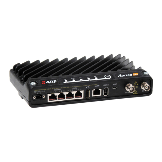
Product Options | 23 Product Options Interface Ports The standard Aprisa SR+ provides multiple interface port options for combinations of Ethernet and RS-232 serial. The product shown below is the two Ethernet ports plus two RS-232 serial ports. Interface Port Option Part Number 4 Ethernet ports and no RS-232 serial ports APSQ-N400-SSC-HD-40-ENAA... -
Page 26: Protected Station
Part Description APSQ-R400-SSC-HD-22-ENAA 4RF SR+, PS, 400-470 MHz, SSC, Half Duplex, 2E2S, EN, AA The Aprisa SR+ Protected Station is comprised of an Aprisa SR+ Protection Switch and two standard Aprisa SR+ radios mounted in a 2U rack mounting chassis. -
Page 27: Operation
Product Options | 25 Operation In hot-standby normal operation, the active radio carries all RS-232 serial and Ethernet traffic over the radio link and the standby radio transmit is on with its transmitter connected to an internal load. Both radios are continually monitored for correct operation including the transmitter and receiver and alarms are raised if an event occurs. -
Page 28: Data Driven Protected Station
Part Description APSQ-D400-SSC-HD-22-ENAA 4RF SR+, PD, 400-470 MHz, SSC, Half Duplex, 2E2S, EN, AA The Aprisa SR+ Data Driven Protected Station shown is comprised of two standard Aprisa SR+ dual antenna port option radios and two external duplexers mounted on 19" rack mounting shelves (as shown above). -
Page 29: Duplexer Kits
2x TNC to SMA right angle 590mm cables Part Number Part Number APSB-KDUP-300-A1 4RF SR+ Acc, Kit, Duplexer, 320-400 MHz, s 5 MHz, p 0.5 MHz, ext APSB-KDUP-400-B1 4RF SR+ Acc, Kit, Duplexer, 400-470 MHz, s 5 MHz, p 0.5 MHz, ext APSB-KDUP-450-M0 4RF SR+ Acc, Kit, Duplexer, 450-520 MHz, s 5 MHz, p 0.5 MHz, ext... -
Page 30: Vhf Duplexer Kits
2x TNC to N type male right angle 590mm cable Part Number Part Number APSB-KDUP-VHF-R2 4RF SR+ Acc, Kit, Duplexer, 152-175 MHz, s4-6 MHz, p100 kHz, High APSB-KDUP-VHF-R3 4RF SR+ Acc, Kit, Duplexer, 152-175 MHz, s6-8 MHz, p100 kHz, High APSB-KDUP-VHF-R4... -
Page 31: Usb Rs-232 Serial Port
Product Options | 29 USB RS-232 Serial Port The Aprisa SR+ USB host port is predominantly used for software upgrade and diagnostic reporting. However, it can also be used to provide an additional RS-232 DCE serial port for customer traffic. This is accomplished with a USB to RS-232 serial converter cable. -
Page 32: Specifications
2 20 -2 22 MHz 220 MHz 2.5 kHz 21 6 -2 2 0 MHz 220 MHz 3.125 kHz 896 MHz 896-902 MHz 6.250 kHz 928 MHz 928-960 MHz 6.250 kHz Note 1: Please consult 4RF for availability. Aprisa SR+ Product Description... -
Page 33: Channel Sizes
Specifications | 31 Channel Sizes ETSI Compliant 135 / 320 / 400 / 450 MHz Bands No Forward Error Correction Channel Size Gross Radio Capacity 64 QAM 16 QAM QPSK 4-CPFSK 12.5 kHz 60.0 kbit/s 40.0 kbit/s 20.0 kbit/s 9.6 kbit/s 25 kHz 120.0 kbit/s 80.0 kbit/s... - Page 34 32 | Specifications FCC / IC Compliant 135 / 400 / 450 MHz Bands No Forward Error Correction Channel Size Gross Radio Capacity 64 QAM 16 QAM QPSK 4-CPFSK 12.5 kHz 54.0 kbit/s 36.0 kbit/s 18.0 kbit/s 9.6 kbit/s 25 kHz 96.0 kbit/s 64.0 kbit/s 32.0 kbit/s...
- Page 35 Specifications | 33 220 / 896 / 928 MHz Bands No Forward Error Correction Channel Size Gross Radio Capacity 64 QAM 16 QAM QPSK 4-CPFSK 12.5 kHz 60.0 kbit/s 40.0 kbit/s 20.0 kbit/s 9.6 kbit/s 25 kHz 96.0 kbit/s 64.0 kbit/s 32.0 kbit/s 19.2 kbit/s 50 kHz...
-
Page 36: Receiver
34 | Specifications Receiver ETSI / FCC / IC Compliant Receiver Sensitivity 12.5 kHz 25 kHz 50 kHz FCC / IC only BER < 10 64 QAM Max coded FEC -106 dBm -102 dBm -99 dBm BER < 10 64 QAM Min coded FEC -105 dBm -101 dBm... - Page 37 Specifications | 35 ETSI / FCC / IC Compliant Adjacent Channel Selectivity 12.5 kHz 25 kHz 50 kHz FCC / IC only Adjacent channel selectivity > -47 dBm > -37 dBm > -37 dBm BER < 10 64 QAM > 43 dB >...
- Page 38 36 | Specifications ETSI / FCC / IC Compliant Spurious Response Rejection 12.5 kHz 25 kHz 50 kHz FCC / IC only Spurious response rejection > -32 dBm > -32 dBm > -32 dBm BER < 10 64 QAM > 58 dB >...
-
Page 39: Transmitter
4-CPFSK 0.01 to 10.0 W (+10 to +40 dBm, in 1 dB steps) Note 1: Please consult 4RF for availability Note: The Aprisa SR+ transmitter contains power amplifier protection which allows the antenna to be disconnected from the antenna port without product damage. -
Page 40: Interface Specifications
38 | Specifications Interface Specifications Ethernet Interface The Aprisa SR+ radio features an integrated 10Base-T/100Base-TX layer-2 Ethernet switch. To simplify network setup, each port supports auto-negotiation and auto-sensing MDI/MDIX. Operators can select from the following preset modes: Auto negotiate 10Base-T half or full duplex 100Base-TX half or full duplex The Ethernet ports are IEEE 802.3-compatible. -
Page 41: Rs-232 Asynchronous Interface
Specifications | 39 RS-232 Asynchronous Interface The Aprisa SR+ radio’s ITU-T V.24 compliant RS-232 interface is configured as a Cisco® pinout DCE. The interface terminates to a DTE using a straight-through cable or to a DCE with a crossover cable (null modem). -
Page 42: Hardware Alarms Interface
40 | Specifications Hardware Alarms Interface The hardware alarms interface supports two alarm inputs and two alarms outputs. Alarm Inputs The alarm connector provides two hardware alarm inputs for alarm transmission to the other radios in the network. Interface RJ45 connector Detector type Non-isolated ground referenced voltage detector... -
Page 43: Power Specifications
Specifications | 41 Power Specifications Power Supply Aprisa SR+ Radio Nominal voltage +13.8 VDC (negative earth) Absolute input voltage range +10 to +30 VDC Maximum power input 35 W Connector Molex 2 pin male screw fitting 39526-4002 Aprisa SR+ Protected Station Nominal voltage +13.8 VDC (negative earth) Absolute input voltage range... -
Page 44: Power Consumption
42 | Specifications Power Consumption Note: The radio power consumption is very dependent on transmitter power, the type of traffic and network activity. Aprisa SR+ Radio Mode Power Consumption (10 W radio with 4-CPFSK modulation) Transmit / Receive < 35 W for 10 W transmit power <... -
Page 45: General Specifications
Specifications | 43 General Specifications Environmental Operating temperature range -40 to +70˚ C (-40 to +158˚ F) Storage temperature range -40 to +80˚ C (-40 to +176˚ F) Operating humidity Maximum 95% non-condensing Acoustic noise emission No audible noise emission Mechanical Aprisa SR+ Radio Dimensions... -
Page 46: Compliance
44 | Specifications Compliance ETSI Radio EN 300 113-2 EMI / EMC EN 301 489 Parts 1 & 5 Safety EN 60950-1:2006 Class 1 div 2 for hazardous locations Environmental ETS 300 019 Class 3.4 Ingress Protection code IP51 Radio 47CFR part 24, part 90 and part 101 Private Land Mobile Radio Services 47CFR part 15 Radio Frequency Devices, EN... -
Page 47: Management
Management | 45 Management SuperVisor The Aprisa SR+ contains an embedded web server application (SuperVisor) to enable element management with any major web browser (such as Mozilla Firefox or Microsoft® Internet Explorer). SuperVisor enables operators to configure and manage the Aprisa SR+ base station radio and repeater / remote station radios over the radio link. -
Page 48: Viewing The Aprisa Sr+ Terminal Settings
46 | Management Viewing the Aprisa SR+ Terminal Settings The SuperVisor software enables operators to view the terminal settings: Aprisa SR+ Product Description... -
Page 49: Configuring The Aprisa Sr+ Terminal Details
Management | 47 Configuring the Aprisa SR+ Terminal Details The SuperVisor software enables operators to set the terminal details including Terminal Name, Location, Contact Name and Contact Details with a maximum of 40 characters. Configuring the Aprisa SR+ RF Network Details The SuperVisor software enables operators to set the RF Network Details including: Network ID Sets the network ID of this base station node and its remote... -
Page 50: Configuring The Aprisa Sr+ Radio Settings
48 | Management Configuring the Aprisa SR+ Radio Settings The SuperVisor software enables operators to set the radio settings including: TX Frequency Sets the transmit frequency in MHz TX Power Sets the transmit Power in dBm RX Frequency Sets the receive frequency in MHz Channel Size Sets the channel size 12.5 kHz, 25 kHz or 50 kHz (depending on variant) -
Page 51: Command Line Interface
Management | 49 Command Line Interface The Aprisa SR+ has a Command Line Interface (CLI) which provides basic product setup and configuration. This interface can be accessed via an Ethernet Port (RJ45) or the Management Port (USB micro type B). The Terminal menu is shown in the following picture: SNMP In addition to web-based management (SuperVisor) and the Command Line Interface, the Aprisa SR... -
Page 52: Led Display Panel
50 | Management LED Display Panel The Aprisa SR+ has an LED Display panel which provides on-site alarms / diagnostics without the need for Normal Operation In normal radio operation, the LEDs indicate the following conditions: MODE Solid Alarm present TX path fail RX path fail with severity... -
Page 53: Single Radio Software Upgrade
Management | 51 Single Radio Software Upgrade During a radio software upgrade, the LEDs indicate the following conditions: Software upgrade started - the OK LED flashes orange Software upgrade progress indicated by running RX to OK LEDs Software upgrade completed successfully - the OK LED solid orange Software upgrade failed - any LED flashing red during the upgrade Network Software Upgrade During a network software upgrade, the MODE LED flashes orange on the base station and all remote... -
Page 54: Applications
52 | Applications Applications This section describes sample Aprisa SR+ radio applications. The following applications are described: Basic point-to-multipoint application Advanced point-to-multipoint application with repeaters Multi-interface point-to-multipoint application Multi-hop Daisy chain repeaters in LBS mode application Pseudo Peer to Peer using base-repeater application Basic point-to-multipoint application Single base station with Ethernet SCADA data inputs to multiple geographically remote sites with Ethernet RTUs requiring control and data acquisition. -
Page 55: Advanced Point-To-Multipoint Application With Repeater
Applications | 53 Advanced point-to-multipoint application with repeater Single base station with Ethernet SCADA data inputs to multiple geographically remote sites with Ethernet RTUs requiring control and data acquisition. A repeater is deployed to service remote sites beyond the reach of the base station. The base station receives Ethernet frames from the SCADA server LAN and broadcasts all Ethernet frames to the repeater and its remote stations. -
Page 56: Multi-Interface Point-To-Multipoint Application
54 | Applications Multi-interface point-to-multipoint application Single base station with Ethernet and RS-232 SCADA data inputs to multiple geographically remote sites with Ethernet and RS-232 RTUs requiring control and data acquisition. The base station receives Ethernet / RS-232 frames from the SCADA servers and broadcasts all frames to all remote stations Each remote site receives Ethernet / RS-232 frames from the RTU and unicasts over the air to the base station. -
Page 57: Multi-Hop Daisy Chain Repeaters In Lbs Mode Application
Applications | 55 Multi-hop Daisy Chain Repeaters in LBS Mode Application This application is used for daisy chain repeaters when remote stations are very far from base station coverage. Daisy chain repeaters can only be used in LBS channel access mode (and future release in AR mode). -
Page 58: Pseudo Peer To Peer Using Base-Repeater Application
56 | Applications Pseudo Peer to Peer using Base-Repeater Application This application is used for remote peer to peer communication via a base-repeater or repeater configuration. In peer to peer, the source RTU will create a message with destination address of the destined RTU in the SCADA layer protocol (and/or IP layer, if applicable). -
Page 59: Product Architecture
Product Architecture | 57 Product Architecture Product Operation There are three components to the wireless interface: the Physical Layer (PHY), the Data Link Layer (DLL) and the Network Layer. These three layers are required to transport data across the wireless channel in the Point-to-multipoint (PMP) configuration. -
Page 60: Hop By Hop Transmission
58 | Product Architecture Access Request This scheme is particularly suited to digital SCADA systems where all data flows through the base station. In this case it is important that the base station has contention-free access as it is involved in every transaction. -
Page 61: Adaptive Coding Modulation
Product Architecture | 59 Adaptive Coding Modulation The Aprisa SR+ provides Adaptive Coding Modulation (ACM) which maximizes the use of the RF path to provide the highest radio capacity available. ACM automatically adjusts the modulation coding and FEC code rate in the remote to base direction of transmission over the defined modulation range based on the signal quality for each individual remote radio. -
Page 62: Network Layer
60 | Product Architecture Network Layer Packet Routing Aprisa SR+ is a standard static IP router which routes and forwards IP packet based on standard IP address and routing table decisions. Aprisa SR+ router mode (see figure below), enables the routing of IP packets within the Aprisa SR+ wireless network and in and out to the external router / IP RTUs devices connected to the Aprisa SR+ wired Ethernet ports. -
Page 63: Static Ip Router
Product Architecture | 61 Static IP Router The Aprisa SR+ works in the point-to-multipoint (PMP) network as a standard static IP router with the Ethernet and wireless / radio as interfaces and serial ports using terminal server as a virtual interface. The Aprisa SR+ static router is semi-automated operation, where the routing table is automatically created in the base station and populated with routes to all remotes and repeater stations in the network during the registration process and vice versa, where the routing table is automatically created in remote... - Page 64 62 | Product Architecture Static IP Router – Human Error Free To ensure correct operation, the Aprisa SR+ router base station alerts when one (or more) of the devices is not configured for router mode or a duplicated IP is detected when manually added. When the user changes the base station IP address / subnet, the base station sends an ARP unsolicited announcement message and the remotes / repeaters auto-update their routing table accordingly.
-
Page 65: Bridge Mode With Vlan Aware
Product Architecture | 63 Bridge Mode with VLAN Aware Ethernet VLAN Bridge / Switch Overview The Aprisa SR+ in Bridge mode of operation is a standard Ethernet Bridge based on IEEE 802.1d or VLAN Bridge based on IEEE 802.1q/p which forward / switch Ethernet packet based on standard MAC addresses and VLANs using FDB (forwarding database) table decisions. -
Page 66: Vlan Bridge Mode Description
64 | Product Architecture VLAN Bridge Mode Description General – Aprisa SR+ VLAN Bridge Aprisa SR+ works in the point-to-multipoint (PMP) network as a standard VLAN bridge with the Ethernet and wireless / radio as interfaces and serial ports using terminal server as a virtual interface. The Aprisa SR+ is a standard IEEE 802.1q VLAN bridge, where the FDB table is created by the bridge learning / aging process. - Page 67 Product Architecture | 65 VLANs – Single, Double and Trunk VLAN ports The Aprisa SR+ supports single VLAN (CVLAN), double VLAN (SVLAN) and trunk VLAN. A single VLAN can be used to segregate traffic type. A double VLAN can be used to distinguish between Aprisa SR+ sub-networks (base-repeater-remote), where the outer SVLAN is used to identify the sub-network and the CVLAN is used to identify the traffic type.
-
Page 68: Avoiding Narrow Band Radio Traffic Overloading
66 | Product Architecture Avoiding Narrow Band Radio Traffic Overloading The Aprisa SR+ supports mechanisms to prevent narrowband radio network overload: L3/L4 Filtering The L3 filtering can be used to block undesired traffic from being transferred on the narrow band channel, occupying the channel and risking the SCADA critical traffic. - Page 69 Product Architecture | 67 Ethernet Data and Management Priority and Background Bulk Data Transfer Rate Alternatively to VLAN priority, users can control the Ethernet traffic priority (vs serial), management priority and rate in order to control the traffic load of the radio network, where important and high priority data (SCADA) will pass-through first assuring SCADA network operation.
-
Page 70: Product Architecture
68 | Product Architecture Product Architecture The following are the key components of the Aprisa SR+ design: Dual high performance ΣΔ fractional-N synthesizers to allow for full duplex operation Wideband design electronically tunes over entire band Proven low noise and spurious technology with over 50dB of SNR easily achieved Power amplifier linearity Unique temperature compensated pre-distortion system improves the efficiency and linearity of the entire transmitter chain for non-constant envelope modulation systems... -
Page 71: Aprisa Sr+ Radio Block Diagram
Product Architecture | 69 Aprisa SR+ Radio Block Diagram Aprisa SR+ Protected Station Block Diagram Aprisa SR+ Product Description... -
Page 72: Contact Us
70 | Contact Us Contact Us For further information or assistance, please contact Customer Support or your local 4RF representative. Our area representative contact details are available from our website: 4RF Limited 26 Glover Street, Ngauranga PO Box 13-506 Wellington 6032...
Need help?
Do you have a question about the Aprisa SR Plus and is the answer not in the manual?
Questions and answers