4RF Aprisa SR+ User Manual
Hide thumbs
Also See for Aprisa SR+:
- User manual (403 pages) ,
- Product description (49 pages) ,
- Manual (12 pages)
Table of Contents
Advertisement
Quick Links
Advertisement
Table of Contents

Related Manuals for 4RF Aprisa SR+


Summary of Contents for 4RF Aprisa SR+
- Page 1 January 2021 Version 1.11.1b...
- Page 3 Copyright © 2021 4RF Limited. All rights reserved. This document is protected by copyright belonging to 4RF Limited and may not be reproduced or republished in whole or part in any form without the prior written permission of 4RF Limited.
- Page 4 Changes or modifications not approved by the party responsible for compliance could void the user’s authority to operate the equipment. Equipment authorizations sought by 4RF are based on the Aprisa SR+ radio equipment being installed at a fixed restricted access location and operated in point-to-multipoint or point-to-point mode within the environmental profile defined by EN 300 019, Class 3.4.
- Page 5 Short Range Device When operating as a short range device under EN 300 220-2 V3.2.1 for Ofcom IR2030/2/6 or IR2030/2/7: 1. The user must operate the Aprisa SR+ radio within all the applicable requirements of IR-2030 2. The transmitter power must not be set above +27 dBm When operating as a short range device, the Aprisa SR+ radio TX power can be adjusted over the range of +10 dBm to +27 dBm (average power).
- Page 6 Compliance United States of America FCC The Aprisa SR+ radio is designed to comply with the Federal Communications Commission (FCC) specifications as follows: Radio 47CFR part 24, part 27, part 90 and part 101 Private Land Mobile Radio Services 47CFR part 15 Radio Frequency Devices (note 1) , EN 301 489-1 and 5...
- Page 7 Compliance Canada ISED The Aprisa SR+ radio is designed to comply with Innovation, Science and Economic Development’ (ISED) specifications as follows: Radio RSS-119 / RSS-134 This Class A digital apparatus complies with Canadian standard ICES-003. Cet appareil numérique de la classe A est conforme à la norme NMB-003 du Canada.
- Page 8 Compliance Hazardous Locations Notice This product is suitable for use in Class 1, Division 2, Groups A - D hazardous locations or non-hazardous locations. A Nationally Recognized Testing Laboratory (NRTL) listed power supply is required to power the equipment. The following text is printed on the Aprisa SR+ fascia: WARNING: EXPLOSION HAZARD - Do not connect or disconnect while circuits are live unless area is known to be non-hazardous.
- Page 9 RF Exposure Warning WARNING: The installer and / or user of Aprisa SR+ radios shall ensure that a separation distance as given in the following table is maintained between the main axis of the terminal’s antenna and the body of the user or nearby persons. Minimum separation distances given are based on the maximum values of the following methodologies: 1.
-
Page 11: Table Of Contents
Who Should Read It ..............19 Contact Us ................. 19 What’s in the Box ................20 About the Radio ............... 21 The 4RF Aprisa SR+ Radio ..............21 Product Features ................22 Functions .................. 22 Security ..................24 Performance ................25 Usability ................... - Page 12 12 | Contents Network Software Upgrade ............. 65 Test Mode ................. 66 Network Management ................67 Hardware Alarm Inputs / Outputs ............68 Alarm Input to SNMP Trap ............... 68 Alarm Input to Alarm Output ............68 Aprisa SR Alarm Input to Aprisa SR+ Alarm Output ........68 Implementing the Network............
- Page 13 Contents | 13 Managing the Radio ..............87 SuperVisor ..................87 Connecting to SuperVisor ............... 88 Management PC Connection ............. 89 PC Settings for SuperVisor ............90 Login to SuperVisor..............94 Logout of SuperVisor .............. 97 SuperVisor Page Layout ............98 SuperVisor Extended Network Management (EXM) ......
- Page 14 14 | Contents Product Options ..............400 Radio Hardware Types ................ 400 Data Interface Ports ................401 Full Duplex Base Station ..............401 Point-To-Point Link ................402 Protected Station ................406 Protected Ports ................. 407 Operation ................407 Switch Over ..............407 Switching Criteria ...............
- Page 15 Contents | 15 10. Maintenance ................437 Spare Fuses ..................437 Radio Spare Fuses ..............437 Additional Spare Fuses ............438 Protected Station Spare Fuses ............439 No User-Serviceable Components ............440 Software Upgrade ................441 Network Software Upgrade ............441 Non-Protected Network Upgrade Process ........
- Page 16 16 | Contents 13. Specifications ................. 463 RF Specifications ................463 Frequency Bands ............... 463 Channel Sizes ................464 Receiver ................. 477 Transmitter ................480 Modem ................... 481 Data Payload Security ..............481 Duplexer Specifications ............... 482 Interface Specifications ..............483 Ethernet Interface ..............
-
Page 17: Getting Started
Getting Started | 17 Getting Started This section is an overview of the steps required to commission an Aprisa SR+ radio network in the field: Phase 1: Pre-installation Confirm path planning. Page 74 Ensure that the site preparation is complete: Page 77 •... - Page 18 18 | Getting Started Phase 3: Establishing the link If radio’s IP address is not the default IP address (169.254.50.10 with a subnet Page 390 mask of 255.255.0.0) and you don’t know the radio’s IP address see ‘Command Line Interface’ on page 390. Connect the Ethernet cable between the radio’s Ethernet port and the PC.
-
Page 19: Introduction
Contact Us If you experience any difficulty installing or using Aprisa SR+ after reading this manual, please contact Customer Support or your local 4RF representative. The 4RF New Zealand head office is: 4RF Limited 26 Glover Street, Ngauranga... -
Page 20: What's In The Box
20 | Introduction What’s in the Box Inside the box you will find: • One Aprisa SR+ radio fitted with a power connector. • One Aprisa SR+ Quick Start Guide: Aprisa SR+ User Manual 1.11.1... -
Page 21: About The Radio
About the Radio The 4RF Aprisa SR+ Radio The 4RF Aprisa SR+ is a Point-To-Multipoint (PMP) and Point-To-Point (PTP) digital radio providing secure narrowband wireless data connectivity for SCADA, infrastructure and telemetry applications. The radios carry a combination of serial data and Ethernet data between the base station, repeater stations and remote radios. -
Page 22: Product Features
22 | About the Radio Product Features Functions • Point-to-Point (PTP) or Point-to-Multipoint (PMP) operation • Licensed frequency bands: VHF 135 135-175 MHz VHF 220 215-240 MHz UHF 320 320-400 MHz UHF 400 400-470 MHz UHF 450 450-520 MHz UHF 700 757-758 MHz and 787-788 MHz UHF 896 896-902 MHz... - Page 23 SuperVisor Extended Network Management (EXM) extending SuperVisor management beyond the single radio network providing configuration and monitoring to other Aprisa SR family products • SNMPv1/2/3 & encryption MIB supports for 4RF SNMP manager or third party SNMP agent network management •...
-
Page 24: Security
SNMPv3 with Encryption for NMS secure access • Secure remote software upgrade using HTTPS protocol • Encrypted and signed software file to prevent the loading of non 4RF software • Secure USB software upgrade • Secure Ethernet port access by user of SCADA / user traffic or management traffic. This is useful to block any management access from unguarded remote sites. -
Page 25: Performance
About the Radio | 25 Performance • Typical deployment of 30 remote radios from one base station with a practical limit of a few hundred remote radios • Long distance operation • High transmit power • Low noise receiver • Forward Error Correction •... -
Page 26: Product Overview
26 | About the Radio Product Overview Network Coverage and Capacity The Aprisa SR+ has a typical link range of up to 120 km, however, geographic features, such as hills, mountains, trees and foliage, or other path obstructions, such as buildings, will limit radio coverage. Additionally, geography may reduce network capacity at the edge of the network where errors may occur and require retransmission. -
Page 27: Store And Forward Repeater
About the Radio | 27 Store and Forward Repeater The Aprisa SR+ in Repeater mode is used to link remote radios to the base station when direct communication is not possible due to terrain, distance, fade margin or other obstructions in the network. The following example depicts a repeater on the hill top to allow communication between the base station and the remote radios on the other side of hilly terrain. - Page 28 28 | About the Radio Multiple Repeater Single Hop The following example depicts an Aprisa SR+ multiple repeater single hop store and forward network supporting both overlapping and non-overlapping coverage repeater networks. An overlapped RF coverage area creates radio interference and might affect network performance and reduce throughput, as show in figure (a), where Remote 1 is in overlapped RF coverage with Repeater 1 and Repeater 2.
- Page 29 About the Radio | 29 Multiple Hop Multiple Repeater Multiple Hop The following example depicts an Aprisa SR+ daisy chain multiple repeater multiple hop store and forward network i.e. multiple hops and multiple repeaters in non-overlapping RF coverage. The Aprisa SR+ daisy chain store and forward repeaters are currently supported in LBS MAC mode only.
-
Page 30: Repeater Messaging
30 | About the Radio Repeater Messaging The Aprisa SR+ uses a routed protocol throughout the network whereby messages contain source and destination addresses. The remote and repeater stations will register with a base station. In networks with a repeater, the repeater must register with the base station before the remotes can register with the base station. -
Page 31: Peer To Peer Communication Between Remote Radios
About the Radio | 31 Peer To Peer Communication Between Remote Radios With the Aprisa SR+ peer to peer communication is possible between remote radios via the repeater or base- repeater. It is useful if the SCADA server or base station fails or when in some industries like the water industry, where a reservoir remote radio might send a direct message to a valve remote radio to close or open the valve without the intervention of the SCADA server. - Page 32 32 | About the Radio The following example depicts peer to peer communication between remote radios via a base-repeater and via a repeater station where remote-1 and remote-2 communicate with each other via the base-repeater station and remote-3 and remote-4 communicate with each other via the repeater station. The repeater, remote-3 and remote-4 radios are configured with packet filtering disabled and all radios in the network are configured with IP header compression ratio disabled.
-
Page 33: Architecture
About the Radio | 33 Architecture The Aprisa SR+ Architecture is based around a layered TCP/IP protocol stack: • Physical Proprietary wireless RS-232 and Ethernet interfaces • Link Proprietary wireless (channel access, ARQ, segmentation) VLAN aware Ethernet bridge • Network Standard IP Proprietary automatic radio routing table population algorithm •... -
Page 34: Data Link Layer / Mac Layer
34 | About the Radio Data Link Layer / MAC layer The Aprisa SR+ PHY enables multiple users to be able to share a single wireless channel; however, a DLL is required to manage data transport. The two key components to the DLL are channel access and hop by hop transmission. -
Page 35: Hop By Hop Transmission
About the Radio | 35 Listen Before Send The Listen Before Send channel access scheme is realized using Carrier Sense Multiple Access (CSMA). In this mode, a pending transmission requires the channel to be clear. This is determined by monitoring the channel for other signals for a set time prior to transmission. -
Page 36: System Gain Vs Fec Coding
36 | About the Radio System Gain vs FEC Coding This table shows the relationship between modulation, FEC coding, system gain, capacity and coverage. • Maximum FEC coding results in the highest system gain, the best coverage but the least capacity •... -
Page 37: Network Layer
About the Radio | 37 Network Layer Packet Routing Aprisa SR+ is a standard static IP router which routes and forwards IP packet based on standard IP address and routing table decisions. Aprisa SR+ router mode (see figure below), enables the routing of IP packets within the Aprisa SR+ wireless network and in and out to the external router / IP RTUs devices connected to the Aprisa SR+ wired Ethernet ports. -
Page 38: Static Ip Router
38 | About the Radio Static IP Router The Aprisa SR+ works in the point-to-multipoint (PMP) network as a standard static IP router with the Ethernet and wireless / radio as interfaces and serial ports using terminal server as a virtual interface. The Aprisa SR+ static router is semi-automated operation, where the routing table is automatically created in the base station and populated with routes to all remotes and repeater stations in the network during the registration process and vice versa, where the routing table is automatically created in remote and repeater... - Page 39 About the Radio | 39 The Radio Network as a Gateway Router The Aprisa SR+ point-to-multipoint radio network can be considered as a gateway router where the ‘network Ethernet interface’ on each radio in the network is the ‘router port’. The routing table for all directly attached devices to the Aprisa SR+ network, at the Base or the Remote radios is automatically built, and no static routes are required to be entered for those device routes.
- Page 40 40 | About the Radio Advanced Gateway Router Mode (AGRM) and Advanced Router Mode (ARM) The Advanced Gateway Router Mode (AGRM) or Advanced Router Mode (ARM) are enabled when either Router or a Gateway Router modes are selected and the Advanced checkbox is ticked (see ‘Terminal > Operating Mode’...
- Page 41 About the Radio | 41 The above figure describes a mixed radio mode network (Bridge-AGRM) where the base station is in Bridge Mode and remote radios are in AGRM. To reach RTU-3 (10.10.1.11), the external router must use a next hop gateway of 192.168.1.4 which is RF Interface address of Remote-2.
- Page 42 42 | About the Radio The following functions supported in AGRM / ARM is the differences between Advanced Router Mode options (AGRM / ARM) and standard Router Mode options Gateway Router Mode (GRM) / Router Mode (RM), such as AGRM vs GRM and/or ARM vs RM: •...
- Page 43 About the Radio | 43 Advanced Gateway Router (AGRM) or Advanced Router Mode (ARM) Static Route – Example The purpose of this example is to determine the static route setting for router R2 in the base station and remote radio in the following AGRM-Bridge, Bridge-AGRM networks. In the above figure, the static route setting for router R2 at the base radio AGRM will be: Destination Address Destination Mask...
- Page 44 44 | About the Radio Static IP Router – Human Error Free To ensure correct operation, the Aprisa SR+ router base station alerts when one (or more) of the devices is not configured for router mode or a duplicated IP is detected when manually added. When the user changes the base station IP address / subnet, the base station sends an ARP unsolicited announcement message and the remotes / repeaters auto-update their routing table accordingly.
- Page 45 About the Radio | 45 Network Address Translation (NAT) Router The NAT functions are only available in Advanced Gateway Router Mode (AGRM) or Advanced Router Mode (ARM). Configuring NAT on the standard router modes will raise a ‘configuration not supported’ alarm. The current implementation of One-to-One NAT and Port Forwarding NAPT supports network configurations of AGRM / ARM mode, such as AGRM / ARM –...
- Page 46 46 | About the Radio Public (External) and Private (Internal/Local) IP Domains The following figure describes the Public (external) and Private (internal/local) IP domains in AGRM / ARM- Bridge network. The NAT IP domains splits at the NAT function enabled device, the AGRM base station. The following figure describes the Public (external) / Private (internal) IP domains in Bridge-AGRM / ARM network.
- Page 47 About the Radio | 47 NAT alarms are supported for any invalid configuration settings, including improper translation entries, invalid timeout, along with any incompatibilities with other feature settings will cause a ‘configuration not supported’ alarm. As shown in the figure of Bridge-AGRM network above, IP addresses used in one NAT internal domain can be reused by any other NAT internal domain.
- Page 48 48 | About the Radio One-to-One NAT Operation The following figure describes an example of a radio network with One-to-One NAT configured at remotes in AGRM mode including the user configuration of NAT Address Map Table and expected session table (a detailed in / outbound session is shown for clarity of explanation, where NAT session table in SuperVisor will show a session in one line which will include inbound / outbound transactions, session duration, statistics, etc).
- Page 49 About the Radio | 49 The NAT session table of remote-1 session ID #1 shows that the public interface RF port address can’t be used in the NAT function or in NAT Address Map Table configuration as it is reserved for the radio access (e.g.
- Page 50 50 | About the Radio Port Forwarding NAT (NAPT) Description Port Forwarding NAT method is based on the remapping (translating) of an external / public TCP/UDP port of a single public IP addresses (e.g. BS radio Eth port-1 IP address) into multiple internal / private IP space (e.g.
- Page 51 About the Radio | 51 Port Forwarding NAT (NAPT) Operation The following figure describes an example of Port Forwarding used for security, hiding the private IP address from the public interface network and it can be used to preserve private IP address even if public IP network subnet might change, reducing operational risk and expense.
- Page 52 52 | About the Radio The configured NAT Address Map Table of the Base Station shows that Port Forwarding NAT will translate; NAT Address Map Table Line 1 configuration will translate public interface Eth-1 IP address 192.168.2.2 port range 8081 - 8087 to private IP address range 10.10.1.1 – 7 and port 80. NAT Address Map Table Line 2 configuration will translate public IP address 192.168.2.2 port range 10,003 –...
-
Page 53: Bridge Mode With Vlan Aware
About the Radio | 53 Bridge Mode with VLAN Aware Ethernet VLAN Bridge / Switch Overview The Aprisa SR+ in Bridge mode of operation is a standard Ethernet Bridge based on IEEE 802.1d or VLAN Bridge based on IEEE 802.1q/p which forward / switch Ethernet packet based on standard MAC addresses and VLANs using FDB (forwarding database) table decisions. -
Page 54: Vlan Bridge Mode Description
54 | About the Radio VLAN Bridge Mode Description General – Aprisa SR+ VLAN Bridge The Aprisa SR+ works in a point-to-multipoint (PMP) network as a standard VLAN bridge with the Ethernet and wireless / radio as interfaces and serial ports using terminal server as a virtual interface. The Aprisa SR+ is a standard IEEE 802.1q VLAN bridge, where the FDB table is created by the bridge learning / aging process. - Page 55 About the Radio | 55 VLANs – Single, Double and Trunk VLAN ports The Aprisa SR+ supports single VLAN (CVLAN), double VLAN (SVLAN) and trunk VLAN. A single VLAN can be used to segregate traffic type. A double VLAN can be used to distinguish between Aprisa SR+ sub-networks (base-repeater-remote), where the outer SVLAN is used to identify the sub-network and the CVLAN is used to identify the traffic type.
-
Page 56: Terminal Server Operational In Bridge And Router Modes
56 | About the Radio Terminal Server Operational in Bridge and Router Modes VLAN and IP address Configuration per Terminal Server in Bridge Mode In all network applications of a converged IP network where serial interfaces are part of an IP network, the remote Terminal Server or IP Terminal Server (generally configured in Base station) associated to a serial interface is part of a SCADA service and as a standalone service. - Page 57 About the Radio | 57 IP and VLAN segregation of IP Terminal Server and radio management The following figure describes the IP and VLAN segregation of IP Terminal Server and radio management. It is the same as the previous example except the IP Terminal Server is configured and used in the Base station with different VLANs and IP addresses from the radio management VLAN and IP.
- Page 58 58 | About the Radio VLAN segregation of IP-Terminal Server and radio management The following figure describes VLAN segregation of the IP Terminal Server and radio management where the IP-Terminal Server in base station is configured with different VLANs from the radio management VLAN and with the same IP address of the radios.
- Page 59 About the Radio | 59 IP address segregation of IP Terminal Server and radio management The following figure describes the IP address segregation of IP Terminal Server and radio management where the IP Terminal Server in Base station is configured with different IP address and subnet from the radio management IP addresses and subnet.
-
Page 60: Avoiding Narrow Band Radio Traffic Overloading
60 | About the Radio Avoiding Narrow Band Radio Traffic Overloading The Aprisa SR+ supports mechanisms to prevent narrowband radio network overload: L3/L4 Filtering The L3 filtering can be used to block undesired traffic from being transferred on the narrow band channel, occupying the channel and risking the SCADA critical traffic. - Page 61 About the Radio | 61 Ethernet Data and Management Priority and Background Bulk Data Transfer Rate Alternatively, to VLAN priority, users can control the Ethernet traffic priority (vs serial), management priority and rate in order to control the traffic load of the radio network, where important and high priority data (SCADA) will pass-through first assuring SCADA network operation.
-
Page 62: Interfaces
62 | About the Radio Interfaces Antenna Interface • 2 x TNC, 50 ohm, female connectors Single or dual antenna ports (with or without the use of external duplexer / filter) Ethernet Interface • 2, 3 or 4 ports 10/100 base-T Ethernet layer 2 switch using RJ45 Used for Ethernet user traffic and radio sub-network management. -
Page 63: Front Panel Connections
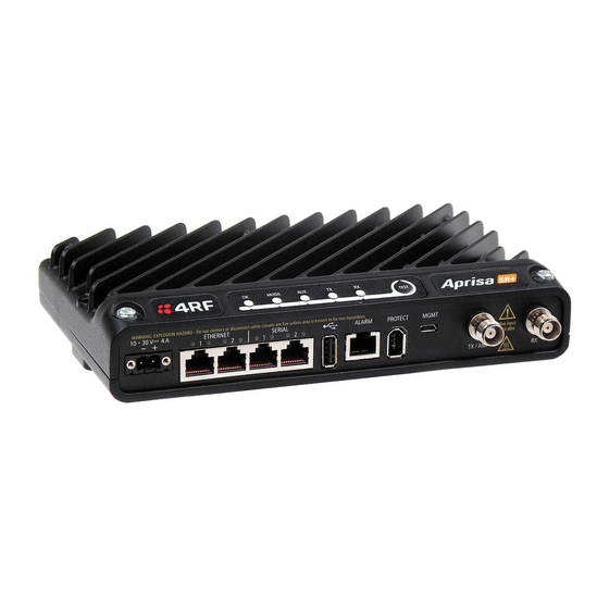
About the Radio | 63 Front Panel Connections Example; 2 Ethernet ports and 2 RS-232 serial ports - see ‘Data Interface Ports’ on page 401 for the other interface port options. Interface Port Option Part Number 2 Ethernet ports and 2 RS-232 serial ports APSQ-N400-SSC-HD-22-ENAA All connections to the radio are made on the front panel. -
Page 64: Led Display Panel
64 | About the Radio LED Display Panel The Aprisa SR+ has an LED Display panel which provides on-site alarms / diagnostics without the need for Normal Operation In normal radio operation, the LEDs indicate the following conditions: MODE Flashing Radio has not registered Alarm present... -
Page 65: Single Radio Software Upgrade
About the Radio | 65 Single Radio Software Upgrade During a radio software upgrade, the LEDs indicate the following conditions: • Software upgrade started - the OK LED flashes orange • Software upgrade progress indicated by running AUX to MODE LEDs •... -
Page 66: Test Mode
66 | About the Radio Test Mode Remote radio and repeater station radios have a Test Mode which presents a real time visual display of the RSSI on the LED Display panel. This can be used to adjust the antenna for optimum signal strength (see ‘Maintenance >... -
Page 67: Network Management
About the Radio | 67 Network Management The Aprisa SR+ contains an embedded web server application (SuperVisor) to enable element management with any major web browser (such as Mozilla Firefox or Microsoft® Internet Explorer). SuperVisor enables operators to configure and manage the Aprisa SR+ base station radio and repeater / remote radios over the radio link. -
Page 68: Hardware Alarm Inputs / Outputs
68 | About the Radio Hardware Alarm Inputs / Outputs The Aprisa SR+ provides two hardware alarm inputs to generate alarm events in the network and two hardware alarm outputs to receive alarm events from the network. The hardware alarm inputs and outputs are part of the event system. All alarm events can be viewed in SuperVisor event history log (see ‘Events >... -
Page 69: Implementing The Network
Implementing the Network | 69 Implementing the Network Network Topologies The following are examples of typical network topologies: Point-To-Point Network Point-to-Multipoint Network Point-to-Multipoint with Repeater 1 Point-to-Multipoint with Repeater 2 Aprisa SR+ User Manual 1.11.1... -
Page 70: Initial Network Deployment
70 | Implementing the Network Initial Network Deployment Install the Base Station To install the base station in your network: 1. Install the base station radio (see ‘Installing the Radio’ on page 80). 2. Set the radio Network ID to a unique ID in your entire network (see ‘Terminal > Device’ on page 111). 3. -
Page 71: Network Changes
Implementing the Network | 71 Network Changes Adding a Repeater Station To add a repeater station to your network: 1. Install the repeater station radio (see ‘Installing the Radio’ on page 80). 2. Set the radio Network ID to the same ID as the other stations in the network (see ‘Terminal > Device’ on page 111). -
Page 73: Preparation
Preparation | 73 Preparation Bench Setup Before installing the links in the field, it is recommended that you bench-test the links. A suggested setup for basic bench testing is shown below: When setting up the equipment for bench testing, note the following: Earthing Each radio should be earthed at all times. -
Page 74: Path Planning
74 | Preparation Path Planning The following factors should be considered to achieve optimum path planning: • Antenna Selection and Siting • Coaxial Cable Selection • Linking System Plan Antenna Selection and Siting Selecting and siting antennas are important considerations in your system design. The antenna choice for the site is determined primarily by the frequency of operation and the gain required to establish reliable links. -
Page 75: Remote Radio
Preparation | 75 Remote radio There are two main types of directional antenna that are commonly used for remote radios, Yagi and corner reflector antennas. Yagi Antennas Factor Explanation Frequency Often used in 350-600 MHz bands Gain Varies with size (typically 11 dBi to 16 dBi) Stackable gain increase 2 Yagi antennas (+ 2.8 dB) -
Page 76: Antenna Siting
76 | Preparation Corner Reflector Antennas Factor Explanation Frequency Often used in 330-960 MHz bands Gain Typically 12 dBi Size Range from 0.36 m to 0.75 m in length Front to back ratio High (typically 30 dB) Beamwidth Broad (up to 60°) Antenna Siting When siting antennas, consider the following points: A site with a clear line of sight to the remote radio is recommended. -
Page 77: Coaxial Feeder Cables
Preparation | 77 Coaxial Feeder Cables To ensure maximum performance, it is recommended that you use good quality low-loss coaxial cable for all feeder runs. When selecting a coaxial cable consider the following: Factor Effect Attenuation Short cables and larger diameter cables have less attenuation Cost Smaller diameter cables are cheaper Ease of installation... -
Page 78: Site Requirements
78 | Preparation Site Requirements Power Supply Ensure a suitable power supply is available for powering the radio. The nominal input voltage for a radio is +13.8 VDC (negative earth) with an input voltage range of +10 to +30 VDC. The maximum power input is 35 W. WARNING: Before connecting power to the radio, ensure that the radio is grounded via the negative terminal of the DC power connection. -
Page 79: Earthing And Lightning Protection
Preparation | 79 Earthing and Lightning Protection WARNING: Lightning can easily damage electronic equipment. To avoid this risk, install primary lightning protection devices on any interfaces that are reticulated in the local cable network. You should also install a coaxial surge suppressor on the radio antenna port. Feeder Earthing Earth the antenna tower, feeders and lightning protection devices in accordance with the appropriate local and national standards. -
Page 80: Installing The Radio
You must comply with the safety precautions in this manual or on the product itself. 4RF does not assume any liability for failure to comply with these precautions. Mounting The Aprisa SR+ has four threaded holes (M4) in the enclosure base and two holes (5.2 mm) through the enclosure for mounting. -
Page 81: Din Rail Mounting
Part Description APSB-MBRK-DIN 4RF SR+ Acc, Mounting, Bracket, DIN Rail The Aprisa SR+ is mounted into the DIN rail mounting bracket using the four M4 threaded holes in the Aprisa SR+ enclosure base. Four 8 mm M4 pan pozi machine screws are supplied with the bracket. -
Page 82: Rack Shelf Mounting
Part Number Part Description APSB-MR19-X1U 4RF SR+ Acc, Mounting, 19" Rack Mount Shelf, 1U WARNING: If the Aprisa SR+ is operated in an environment where the ambient temperature exceeds 50°C, the Aprisa SR+ convection air flow over the heat sinks must be considered. -
Page 83: Wall Mounting
Installing the Radio | 83 Wall Mounting The Aprisa SR+ can be mounted on a wall using the two holes through the enclosure (5.2 mm diameter). Typically, M5 screws longer than 35 mm would be used. Aprisa SR+ User Manual 1.11.1... -
Page 84: Installing The Antenna And Feeder Cable
84 | Installing the Radio Installing the Antenna and Feeder Cable Carefully mount the antenna following the antenna manufacturers’ instructions. Run feeder cable from the antenna to the radio location. Lightning protection must be incorporated into the antenna system (see ‘Earthing and Lightning Protection’ on page 79). -
Page 85: Connecting The Power Supply
Wire your power source to power connector and plug the connector into the radio. The connector screws can be fastened to secure the connector. Spare Molex 2 pin female power connectors can be ordered from 4RF: Part Number Part Description... -
Page 87: Managing The Radio
Managing the Radio | 87 Managing the Radio SuperVisor The Aprisa SR+ contains an embedded web server application (SuperVisor) to enable element management with any major web browser (such as Mozilla Firefox or Microsoft® Internet Explorer). SuperVisor enables operators to configure and manage the Aprisa SR+ base station radio and repeater / remote radios over the radio link. -
Page 88: Connecting To Supervisor
88 | Managing the Radio Connecting to SuperVisor The predominant management connection to the Aprisa SR+ radio is with an Ethernet interface using standard IP networking. There should be only one Ethernet connection from the base station to the management network. The Aprisa SR+ has a factory default IP address of 169.254.50.10 with a subnet mask of 255.255.0.0. -
Page 89: Management Pc Connection
Managing the Radio | 89 Management PC Connection The active management PC must only have one connection to the network as shown by path . There should not be any alternate path that the active management PC can use via an alternate router or alternate LAN that would allow the management traffic to be looped as shown by path . -
Page 90: Pc Settings For Supervisor
90 | Managing the Radio PC Settings for SuperVisor To change the PC IP address: If your PC has previously been used for other applications, you may need to change the IP address and the subnet mask settings. You will require Administrator rights on your PC to change these. Windows XP example: 1. - Page 91 Managing the Radio | 91 To change the PC connection type: If your PC has previously been used with Dial-up connections, you may need to change your PC Internet Connection setting to ‘Never dial a connection’. Windows Internet Explorer 8 example: 1.
- Page 92 92 | Managing the Radio To change the PC pop-up status: Some functions within SuperVisor require Pop-ups enabled e.g. saving a MIB Windows Internet Explorer 8 example: 1. Open Internet Explorer. 2. Open the menu item Tools > Internet Options and click on the ‘Privacy’ tab. 3.
- Page 93 Managing the Radio | 93 To enable JavaScript in the web browser: Some functions within SuperVisor require JavaScript in the web browser to be enabled. Windows Internet Explorer 8 example: 1. Open Internet Explorer. 2. Open the menu item Tools > Internet Options and click on the ‘Security’ tab. 3.
-
Page 94: Login To Supervisor
It is safe to ignore the warning and continue. The valid certificate is ‘Issued By: 4RF-APRISA’ which can be viewed in the browser. 2. Login with the Username and Password assigned to you. - Page 95 Managing the Radio | 95 SuperVisor will display a warning popup upon multiple consecutive failed login attempts on the same account. SuperVisor has login protection options which provide protection against unsuccessful login retries (see Security > Users ‘Login Protection Mode’ on page 240). If login protection is active and a login attempt failed due to temporary lockout of the account (Level 1 or Level 2 lockout), SuperVisor will display an ‘Account Locked’...
- Page 96 96 | Managing the Radio Recover If a login attempt failed due to permanent lockout of the account or the Admin password is unknown, click the ‘Recover’ button to start the recovery process. If the user account is not an ADMIN account, or if the account does not have an associated ‘Standard OPT’ password entered (see ‘One-time Password Recovery’...
-
Page 97: Logout Of Supervisor
Managing the Radio | 97 If the login is successful, the opening Terminal > Summary page will be displayed. Important: After you login for the very first time, it is recommended that you change the default admin password for security reasons (see ‘Security > Users’ on page 240). If there is more than one user logged into the same radio, the Multiple Management Sessions popup will show the usernames and IP addresses of the users. -
Page 98: Supervisor Page Layout
98 | Managing the Radio SuperVisor Page Layout Standard Radio The following shows the components of the SuperVisor page layout for a standard radio: SuperVisor Branding Bar The branding bar at the top of the SuperVisor frame shows the branding of SuperVisor on the left and the product branding on the right. - Page 99 Managing the Radio | 99 SuperVisor Alarm Bar The alarm bar shows the name of the radio terminal that SuperVisor is logged into (the local radio) on the left. If the local radio is a base station, the page shows the name of the current remote / repeater station (the remote radio) on the right.
-
Page 100: Supervisor Extended Network Management (Exm)
Some of the benefits that will be seen from this enhancement include: • Ability to use SuperVisor to manage any 4RF compatible radio units via the ‘closest radio station’ • A user can now simply establish a local connection with the closest radio and navigate to manage another radio down the RF path from the radio logged into. - Page 101 Managing the Radio | 101 Extended Network Management (EXM) Setup 1. Enable Network Extension Mode on all radios required in the extended network radio list including the radio logged into, the remote radio being used to extend management, the destination base station and any remote radios off that base station requiring management.
-
Page 102: Supervisor Menu
102 | Managing the Radio SuperVisor Menu The following is a list of SuperVisor top level menu items: Local Terminal Network Network Table Terminal Summary Radio Exceptions Serial View Ethernet Security Maintenance Events Software Monitoring SuperVisor Parameter Settings Changes to parameters settings have no effect until the ‘Save’ button is clicked. Click the ‘Save’... -
Page 103: Supervisor Menu Access
Managing the Radio | 103 SuperVisor Menu The SuperVisor menu has varying access levels dependent on the login User Privileges. The following is a list of all possible SuperVisor menu items versus user privileges: Terminal Settings Menu Items Menu Item View Technician Engineer... - Page 104 104 | Managing the Radio Menu Item View Technician Engineer Admin Maintenance > Test Mode No Access Read-Write Read-Write Read-Write Maintenance > Modem No Access Read-Write Read-Write Read-Write Maintenance > Defaults No Access No Access No Access Read-Write Maintenance > RF No Access No Access No Access...
-
Page 105: Supervisor Menu Items
Managing the Radio | 105 Network Settings Menu Items Menu Item View Technician Engineer Admin Network Table Read-Only Read-Only Read-Only Read-Only Summary Read-Only Read-Only Read-Only Read-Only Exceptions Read-Only Read-Only Read-Only Read-Only View Read-Only Read-Only Read-Only Read-Only SuperVisor Menu Items As SuperVisor screens are dependent on the Aprisa SR+ configuration deployed, the following section is split into two sections: •... -
Page 106: Standard Radio
106 | Managing the Radio Standard Radio Terminal Terminal > Summary TERMINAL SUMMARY This page displays the current settings for the Terminal parameters. See ‘Terminal > Details’ on page 109, ‘Terminal > Device’ on page 111 and ‘Terminal > Operating Mode’ on page 119 for setting details. OPERATING SUMMARY Operating Mode This parameter displays the current Operating Mode i.e. - Page 107 Managing the Radio | 107 TX Frequency (MHz) This parameter displays the current Transmit Frequency in MHz. TX Power (dBm) This parameter displays the current Transmit Power in dBm. RX Frequency (MHz) This parameter displays the current Receive Frequency in MHz. Channel Size (kHz) This parameter displays the current Channel Size in kHz.
- Page 108 108 | Managing the Radio Repeater Network Segment ID This parameter identifies the repeater network segment this radio belongs to. This allows a remote to communicate only with the correct base/repeater for improved reliability, and also allows improved performance by only forwarding through a repeater when a packet is destined for that repeater segment. The base station and each repeater should be assigned a unique value between 1 and 31.
- Page 109 Managing the Radio | 109 Terminal > Details MANUFACTURING DETAILS Radio Serial Number This parameter displays the Serial Number of the radio (shown on the enclosure label). Sub-Assembly Serial Number This parameter displays the Serial Number of the printed circuit board assembly (shown on the PCB label). Aprisa SR+ User Manual 1.11.1...
- Page 110 110 | Managing the Radio HW Frequency Band This parameter displays the hardware radio frequency operating range. HW Type This parameter displays the radio hardware type (see ’Radio Hardware Types’ on page 400). Radio MAC Address This parameter displays the MAC address of the radio (the management Ethernet MAC address). Active Software Version This parameter displays the version of the software currently operating the radio.
- Page 111 1. Enter the Terminal Name. 2. Enter the Location of the radio. 3. Enter a Contact Name. The default value is ‘4RF Limited’. 4. Enter the Contact Details. The default value is ‘support@4RF.com’. Aprisa SR+ User Manual 1.11.1...
- Page 112 112 | Managing the Radio GPS Coordinates This parameter sets the GPS Coordinates for the radio location. It can be manually entered and saved or if the radio is fitted with a GPS Receiver, it can be set by clicking on the Update GPS button. The entry is two values of latitude and longitude comma delimited;...
- Page 113 Managing the Radio | 113 REGION SETTINGS Time Format This parameter sets the time format for all time based results. The default setting is 24 Hours. Date Format This parameter sets the date format for date based results. The default setting is DD/MM/YYYY. Measurement System This parameter sets the unit type for parameters like temperature readings.
- Page 114 114 | Managing the Radio Network Repeaters Proximity Network Radius > 1 This parameter is set in base stations, remote radios and repeater stations to indicate the proximity of repeaters in the network when the Network Radius is set to greater than 1. All radios in the network must be set the same.
- Page 115 Managing the Radio | 115 Repeater Network Segment ID This parameter identifies the repeater network segment this radio belongs to. This allows a remote to communicate only with the correct base/repeater for improved reliability, and also allows improved performance by only forwarding through a repeater when a packet is destined for that repeater segment. The base station and each repeater should be assigned a unique value between 1 and 31.
- Page 116 116 | Managing the Radio Terminal > Date / Time TERMINAL DATE AND TIME Sets the radio Date and Time. This information is controlled from a software clock. Time Set Method This parameter sets the method for setting the Date and Time. The default setting is Manual. Option Function Manual...
- Page 117 Managing the Radio | 117 Time Zone Offset The Time Zone Offset is the number of hours / minutes offset from UTC time. The default setting is ‘No Offset’. Clicking the Time Zone Offset field brings up a pop-up to enter the offset. After selecting the offset, review the current date and time before saving the changes.
- Page 118 118 | Managing the Radio Date and Time This sets the radio Date and Time. Clicking the Date and Time field brings up a pop-up to enter the date and time. The ‘Set from Browser’ button sets the date and time directly from the browser date and time. If the Set from Browser button is used and the offset for the browser and the radio are different, then SuperVisor will adjust the time displayed in the text box to be the local time for the radio e.g.
- Page 119 Managing the Radio | 119 Terminal > Operating Mode OPERATING MODES Terminal Operating Mode The Terminal Operating Mode can be set to Base, Base Repeater, Repeater, Remote or Point-To-Point station. The default setting is Remote. Option Function Base The base station manages all traffic activity between itself, repeaters and remotes.
- Page 120 120 | Managing the Radio When the Terminal Operating Mode is changed from PMP to PTP or vice versa, the following popup will warn of the ‘restore to factory default settings’. SR Compatible The SR Compatible option enables over-the–air point-to-multipoint interoperation between an Aprisa SR+ network and New Aprisa SR radios.
- Page 121 Managing the Radio | 121 Ethernet Operating Mode The Ethernet Operating Mode defines how Ethernet / IP traffic is processed in the radio. The default setting is Bridge. Option Function Bridge Bridge mode inspects each incoming Ethernet frame source and destination MAC addresses to determine if the frame is forwarded over the radio link or discarded.
- Page 122 122 | Managing the Radio RF Operating Mode The RF Operating Mode defines the operation of the RF over-the-air. The default setting is Standard. Option Function Standard The radio operates normally. Disabled Disables all RF over-the-air communications from the RF port and turns off the transmitter and receiver to save power.
- Page 123 Managing the Radio | 123 Terminal > Sleep Mode Sleep Mode is a feature of Type B Aprisa SR+ radios. This page is only visible when the radio is of Type B hardware see ‘Radio Hardware Types’ on page 400. SLEEP MODE SETTINGS Sleep mode allows the radio to be put to sleep where it consumes very little power (<...
- Page 124 124 | Managing the Radio Sleep Mode The Sleep Mode parameter sets how sleep mode is controlled. The default setting is Automatic. Option Function Automatic If this radio is a remote, it uses the setting from the base station. If this radio is the base station, the external triggers control the radio sleep mode state.
- Page 125 2. Login to the CLI. The default login is Login: ‘admin’ Password: ‘admin’ 3. At the CLI prompt >> type ‘cd APRISASR-MIB-4RF’ enter 4. At the CLI prompt >> type ‘set ethPort1Enabled 1’ enter (for port 1)
- Page 126 126 | Managing the Radio RECEIVE IDLE SETTINGS Radio power consumption in idle mode is lowered by turning off the receiver when remote radios know that packet reception is not possible. This feature only works with the Access Request MAC as the Listen Before Send MAC cannot know that packet reception is not possible.
-
Page 127: Radio
Managing the Radio | 127 Radio Radio > Radio Summary This page displays the current settings for the Radio parameters. See ‘Radio > Radio Setup’ and ‘Radio > Channel Setup’ for setting details. Aprisa SR+ User Manual 1.11.1... - Page 128 128 | Managing the Radio Radio > Channel Summary This page displays the current settings for the Channel parameters. See ‘Radio > Channel Setup’ for setting details. DATA COMPRESSION IP Header Compression Ratio See ‘IP Header Compression Ratio’ on page 147. Payload Compression Ratio The payload is compressed using level 3 QuickLZ data compression.
- Page 129 Managing the Radio | 129 Radio > Radio Setup Transmit frequency, transmit power and channel size would normally be defined by a local regulatory body and licensed to a particular user. Refer to your site license details when setting these fields. RF CONFIGURATION RF configuration profiles allows for two sets of TX Frequency, RX Frequency, TX Power and ATPC.
- Page 130 130 | Managing the Radio The RSSI set point is set per channel size to maintain enough fade margin for typical operation. If there is a change in the RSSI level of >10dB received at the base station, then the remote radio will be instructed to increase its level immediately and not wait the one minute.
- Page 131 Managing the Radio | 131 RADIO HARDWARE The radio hardware displays the radio TX Frequency, RX Frequency and TX Power specifications. TX and RX Frequencies. The TX and RX frequencies entered must be within the frequency tuning range of the product frequency band (see ‘Frequency Bands’...
- Page 132 132 | Managing the Radio Single Frequency Operation The TX and RX frequencies of the base station, repeater station and all the remote radios are on the same frequency. To change the TX and RX frequencies: 1. Change the TX and RX frequencies of the remote radios operating from the repeater station to the new frequency.
- Page 133 Managing the Radio | 133 Dual Frequency No Repeater The TX frequency of all the remote radios matches the RX frequency of the base station. The RX frequency of all the remote radios matches the TX frequency of the base station. To change the TX and RX frequencies: 1.
- Page 134 134 | Managing the Radio Dual Frequency with Repeater The TX frequency of the remote radios associated with the base station matches the RX frequency of the base station. The TX frequency of the repeater station associated with the base station matches the RX frequency of the base station.
- Page 135 Managing the Radio | 135 To change the TX and RX frequencies: 1. For all the remote radios operating from the repeater station, change the RX frequency to frequency A and the TX frequency to frequency B. The radio links to these remote radios will fail. 2.
- Page 136 136 | Managing the Radio MODEM The Radio > Radio Setup screen Modem section is different for a base / repeater / base-repeater station and a remote radio. Modem Mode This parameter sets the Modem Mode in the radio. The Modem Mode option list is dependent on the radio hardware frequency band variant (see ‘Terminal >...
- Page 137 Managing the Radio | 137 HW Variant Option Channel Size Symbol Rate ksps 896 MHz Mode A (FCC / ISED) 12.5 Mode B (FCC Part 24) 12.5 Mode C (ISED RSS-134) 12.5 928 MHz Mode A (FCC) 12.5 Mode B (ISED) 12.5 Mode C (FCC Part 24) 12.5...
- Page 138 138 | Managing the Radio Modulation Type This parameter sets the TX Modulation Type for the radio. Option Function Adaptive Sets the transmit modulation to Adaptive Coding Modulation (ACM). QPSK (High Gain) Sets the modulation to QPSK with Max Coded FEC. QPSK (Low Gain) Sets the modulation to QPSK with Min Coded FEC.
- Page 139 Managing the Radio | 139 ACM Control This parameter enables / disables Adaptive Code Modulation in the receive direction. When ACM is enabled (ACM Control set to Standard or Fast), the radio sends a modulation type recommendation to the peer radio based on the signal quality for each individual radio. Option Function Disabled...
- Page 140 140 | Managing the Radio ADAPTIVE CODING MODULATION Default Modulation This parameter is used when ACM is enabled but the far end of the link has ACM disabled. In repeater networks this parameter is always used as the transmit modulation for base to repeater and repeater to base packets.
- Page 141 Managing the Radio | 141 GENERAL Channel Size (kHz) This parameter sets the Channel Size for the radio (see ‘Channel Sizes’ on page 464 for Radio Capacities). The default setting is 12.5 kHz. Antenna Port Configuration This parameter sets the Antenna Port Configuration for the radio. Option Function Single Antenna...
- Page 142 142 | Managing the Radio Radio > Channel Setup CHANNEL SETTINGS Access Scheme This parameter sets the Media Access Control (MAC) used by the radio for over the air communication. Option Function Access Request Channel access scheme where the base station controls the communication on the channel.
- Page 143 Managing the Radio | 143 Listen Before Send Channel access scheme where network elements listen to ensure the with channel is clear, before trying to access the channel. This mode is Acknowledgement optimized for low load networks and repeated networks. With Acknowledgement, unicast requests from the remote radio are acknowledged by the base station to ensure that the transmission has been successful.
- Page 144 144 | Managing the Radio Packet Filtering Each Aprisa SR+ radio can filter packets not destined for itself. The Packet Filtering parameter controls this functionality. Normally all packets sent by remotes and repeaters are only received at the base station. Setting packet filtering to disabled can provide the ability for remote radios to communicate with each other (peer to peer communication) when connected to a repeater station, particularly useful in the event of losing communication with a SCADA Master, assuming the Aprisa SR+ network is still operational.
- Page 145 Managing the Radio | 145 Serial Data Stream Mode This parameter controls the traffic flow in the radio serial ports. Option Function Broadcast Serial port traffic from the network is broadcast on all serial ports on this radio. This will include the RS-232 port derived from the USB port.
- Page 146 146 | Managing the Radio TRAFFIC SETTINGS Background Bulk Data Transfer Rate This parameter sets the data transfer rate for large amounts of management data. Option Function High Utilizes more of the available capacity for large amounts of management data. Highest impact on user traffic. Medium Utilizes a moderate of the available capacity for large amounts of management data.
- Page 147 Managing the Radio | 147 DATA COMPRESSION IP Header Compression Ratio The IP Header Compression implements TCP/IP ROHC v2 (Robust Header Compression v2. RFC4995, RFC5225, RFC4996) to compress the IP header. IP header compression allows for faster point-to-point transactions, but only in a star network. IP Header Compression module comprises of two main components, compressor and decompressor.
- Page 148 148 | Managing the Radio Radio > Advanced Setup This page is only visible when the Channel Setup > Network Traffic Type is set to User Defined. ADVANCED CHANNEL SETTINGS Default Packet Time to Live (ms) This parameter sets the time packets that are neither Serial nor Ethernet (such as registration, inter-unit messaging, firmware distribution etc).
-
Page 149: Serial
Managing the Radio | 149 Serial Serial > Summary RS-232 Hardware Ports This page displays the current settings for the serial port parameters. Note: This screen is dependent on the Data Port product option purchased (see ‘Data Interface Ports’ on page 401). - Page 150 150 | Managing the Radio USB Serial Ports This page displays the current settings for the USB serial port parameters. Type This parameter displays the Serial Port interface type. If the Name is USB Serial Port: Option Function RS-232 Indicates that a RS-232 USB device is plugged into the radio. RS-485 Indicates that a RS-485 USB device is plugged into the radio.
- Page 151 Managing the Radio | 151 Serial > Port Setup RS-232 Hardware Ports This page provides the setup for the serial port settings. SERIAL PORTS SETTINGS Note: This screen is dependent on the Data Port product option purchased (see ‘Data Interface Ports’ on page 401).
- Page 152 152 | Managing the Radio Mode This parameter defines the mode of operation of the serial port. The default setting is Standard. Option Function Disabled The serial port is not required. Standard The serial port is communicating with serial ports on other stations.
- Page 153 Managing the Radio | 153 Parity This parameter sets the parity to Even, Odd or None. The default setting is None. Stop Bits (bits) This parameter sets the number of stop bits to 1 or 2 bits. The default setting is 1 bit. Flow Control This parameter sets the flow control of the serial port.
- Page 154 154 | Managing the Radio Bit Oriented This menu item is only applicable if the serial port has an operating mode of Bit Oriented. This mode allows support for legacy protocols that are not compatible with standard UARTs. Examples are VANCOMM, REDAC, CONITEL, and CDC, although others will work as well.
- Page 155 Managing the Radio | 155 Mirrored Bits® This menu item is only applicable if the serial port has an operating mode of Mirrored Bits. Introduction Mirrored Bits® is a serial communications protocol used to exchange internal logic status messages directly between relays and devices used in line protection, remote control and monitoring, relay remote tripping, sectionalizing and other such applications.
- Page 156 • 321 series relays 4RF is working with customers to confirm support for other devices as they are identified. The remainder of this document details the configuration settings and general process to optimize the radio to support additional devices, in addition to listing expected latencies under different configurations.
- Page 157 Two key serial port parameters will be adjusted during optimization. The following initial values have been determined as a suitable for the SEL 2505 device which is the fastest device 4RF has lab tested. It is a suitable start point to carry out optimization for other devices.
- Page 158 Note if the serial baud rate intended to be used is not 9600 then repeat for each different rate and clearly identify the screen prints by baud rate before forwarding to 4RF Note there are additional low level configurations which can improve performance. 4RF will detail these if required based on the information received.
- Page 159 Managing the Radio | 159 Baud rate and Latency Table The following table is arranged by serial baud rate followed by Aprisa SR+ channel size and modulation. It lists the optimized MTU and IFG and resulting latency for the SEL 2505 device, one of the faster devices available so serves as an ideal starting point when introducing new devices.
- Page 160 160 | Managing the Radio Terminal Server This menu item is only applicable if the serial port has an operating mode of Terminal Server. The Terminal Server operating mode provides encapsulation of serial data from a local serial port into an IP packet (over TCP or UDP).
- Page 161 Managing the Radio | 161 Inactivity Timeout (seconds) This specifies the duration (in seconds) to automatically terminate the connection with the remote TCP server if no data has been received from either the remote TCP server or its associated serial port for the duration of the configured inactivity time.
- Page 162 162 | Managing the Radio Local Port This parameter sets the TCP or UDP port number of the local serial port. The valid port number range is less than or equal to 49151 but with exclusions of 0, 20, 21, 23, 80, 161, 162, 443, 5445, 6445, 9930 or 9931.
- Page 163 Managing the Radio | 163 Serial Line Interface Protocol (SLIP) This menu item is only applicable if the serial port has an operating mode of SLIP. The SLIP operating mode provides IP packet encapsulation over RS-232 serial interface as per the SLIP protocol RFC 1055.
- Page 164 164 | Managing the Radio USB Serial Ports This page provides the setup for the USB serial port settings. SERIAL PORTS SETTINGS Mode This parameter defines the mode of operation of the serial port. The default setting is Disabled. Option Function Disabled The serial port is not required.
- Page 165 Managing the Radio | 165 MTU Size (bytes) This parameter sets the size of the packet in bytes received before it is transmitted if an inter-frame gap is not detected. Setting a smaller MTU may reduce latency, but this should only be done with streaming mode or else if serial protocol is known to allow gaps at the receiver.
- Page 166 166 | Managing the Radio Inter-Frame Gap (chars) This parameter defines the gap between successive serial data frames. It is used to delimit the serial data to define the end of a packet. Smaller values give better serial latency, however if this value is too small then packets may be incorrectly split and serial speed may be much slower.
- Page 167 Managing the Radio | 167 GPS Receiver This menu item is only applicable if a GPS Receiver device is plugged into the radio USB port. The radio USB port supports NMEA 0183 - a combined electrical and data specification for communication between electronics systems and GPS receivers.
-
Page 168: Ethernet
168 | Managing the Radio Ethernet Ethernet > Summary This page displays the current settings for the Ethernet port parameters and the status of the ports. See ‘Ethernet > Port Setup’ for configuration options. Aprisa SR+ User Manual 1.11.1... - Page 169 Managing the Radio | 169 Ethernet > Port Setup This page provides the setup for the Ethernet ports settings. ETHERNET PORT SETTINGS Note: This screen is dependent on the Data Port product option purchased (see ‘Data Interface Ports’ on page 401). The Data Port product option shown is a 2E2S – two Ethernet ports and two Serial ports Mode This parameter controls the Ethernet traffic flow.
- Page 170 170 | Managing the Radio Speed (Mbit/s) This parameter controls the traffic rate of the Ethernet port. The default setting is Auto. Option Function Auto Provides auto selection of Ethernet Port Speed 10/100 Mbit/s The Ethernet Port Speed is manually set to 10 Mbit/s The Ethernet Port Speed is manually set to 100 Mbit/s Duplex This parameter controls the transmission mode of the Ethernet port.
- Page 171 Managing the Radio | 171 Ethernet > L2 Filtering This page is only available if the Ethernet traffic option has been licensed (see ‘Maintenance > Licence’ on page 270). FILTER DETAILS L2 Filtering provides the ability to filter (white list) radio link user traffic based on specified Layer 2 MAC addresses.
- Page 172 172 | Managing the Radio Protocol Type This parameter sets the EtherType accepted ARP, VLAN, IPv4, IPv6 or Any type. Example: In the screen shot, the rules are configured in the base station which controls the Ethernet traffic to the radio link.
- Page 173 Managing the Radio | 173 Ethernet > VLAN This page is only available if the Ethernet traffic option has been licensed (see ‘Maintenance > Licence’ on page 270). VLAN PORT SETTINGS – All Ports This page specifies the parameters that relate to all Ethernet ports when working in Bridge Mode. Three parameters are global parameters for the Ethernet Bridge;...
- Page 174 174 | Managing the Radio Double Tag Egress S-VLAN Priority This parameter sets the S-VLAN egress traffic priority. The default is Priority 1 (Best Effort). Option Egress Priority High / Low Classification Priority Priority 0 Background Lowest Priority Priority 1 (Best Effort) Priority 2 (Excellent Effort) Priority 3 (Critical Applications) Priority 4 (Video)
- Page 175 Managing the Radio | 175 VLAN PORT SETTINGS – Port 1 This example is shown for the product option of 2E2S i.e. two Ethernet ports. PORT PARAMETERS Ingress Filtering Enabled This parameter enables ingress filtering. When enabled, if ingress VLAN ID is not included in its member set (inner tagged), the frame will be discarded.
- Page 176 176 | Managing the Radio If double tagging is enabled on the port, incoming frames should always be double tagged. • If the incoming frame is untagged, then the PVID (port VLAN ID) is used and forwarded with the Port Ingress priority provided the PVID is configured in the Port VLAN Membership of any of the Ethernet ports.
- Page 177 Managing the Radio | 177 Egress Action This parameter sets the action taken on the frame on egress from the Ethernet port. The default is Untag and forward. Option Function Untag and forward Removes the tagged information and forwards the frame.
- Page 178 178 | Managing the Radio IP > IP Summary > Bridge / Gateway Router Modes This page displays the current settings for the Networking IP Settings for an Ethernet Operating Mode of ‘Bridge’ or ‘Gateway Router’. See ‘IP > IP Setup > Bridge / Gateway Router Modes’ on page 183 for configuration options. Aprisa SR+ User Manual 1.11.1...
- Page 179 Managing the Radio | 179 IP > IP Summary > Router Mode This page displays the current settings for the Networking IP Settings for an Ethernet Operating Mode of ‘Router’. See ‘IP > IP Setup > Router Mode’ on page 184 for configuration options. Aprisa SR+ User Manual 1.11.1...
- Page 180 180 | Managing the Radio IP > IP Summary > Advanced Gateway Router Mode This page displays the current settings for the Networking IP Settings for an Ethernet Operating Mode of ‘Gateway Router’ with Advanced. See ‘Advanced Gateway Router Mode (AGRM) and Advanced Router Mode (ARM)’ on page 40 for a detailed explanation of advanced router modes.
- Page 181 Managing the Radio | 181 IP > IP Summary > Advanced Router Mode This page displays the current settings for the Networking IP Settings for an Ethernet Operating Mode of ‘Router’ with Advanced. See ‘Advanced Gateway Router Mode (AGRM) and Advanced Router Mode (ARM)’ on page 40 for a detailed explanation of advanced router modes.
- Page 182 182 | Managing the Radio IP > Terminal Server Summary This page displays the current IP Terminal Server settings. TERMINAL SERVER SUMMARY IP Terminal Server converts local incoming IP packets to a local physical serial port and to OTA serial packets. This function is typically used on a base station to convert traffic to serial OTA for transmission to all remote radios.
- Page 183 Managing the Radio | 183 IP > IP Setup > Bridge / Gateway Router Modes This page provides the setup for the IP Settings for an Ethernet Operating Mode of ‘Bridge’ or ‘Gateway Router’. NETWORKING IP SETTINGS IP Address Set the static IP Address of the radio (Management and Ethernet ports) assigned by your site network administrator using the standard format xxx.xxx.xxx.xxx.
- Page 184 184 | Managing the Radio IP > IP Setup > Router Mode This page provides the setup for the IP Settings for and Ethernet Operating Mode of ‘Router’. PORT SETTINGS – port (n) Note: This screen is dependent on the Data Port product option purchased (see ‘Data Interface Ports’ on page 401).
- Page 185 Managing the Radio | 185 IP MTU Size (bytes) Sets the IP Maximum Transmission Unit (MTU). The IP MTU can be configured on each IP interface to improve compatibility and/or performance when integrating with devices using smaller than standard MTU sizes. The default setting is 1500. RADIO INTERFACE IP SETTINGS The RF interface IP address is the address that traffic is routed to for transport over the radio link.
- Page 186 186 | Managing the Radio IP > Terminal Server Setup This page provides the setup for the IP Terminal Server settings. TERMINAL SERVER Enabled This parameter enables IP terminal server. IP terminal server converts local incoming IP packets to a local physical serial port and to OTA serial packets as well.
- Page 187 Managing the Radio | 187 Serial Port This parameter selects the serial port to use IP terminal server. Option Function Serial Port This is the normal RS-232 serial ports provided with the RJ45 connector. USB Serial Port This is the optional RS-232 / RS-485 serial port provided with the USB host port connector with a USB to RS-232 / RS-485 RJ45 converter cable (see ‘USB RS-232 / RS-485 Serial Port’...
- Page 188 188 | Managing the Radio PVID This parameter sets the PVID (port VLAN ID) for each of the terminal servers on the radio. Protocol Conversion This parameter defines the mode of operation of the terminal server connection. The default setting is None.
- Page 189 Managing the Radio | 189 Protocol This parameter sets the L4 TCP / IP or UDP / IP protocol used for terminal server operation. The default setting is TCP. Gateway IP Address This Terminal Server parameter sets the Gateway IP address of a router in the network that serves as the forwarding router to other networks when no other route specification matches the destination IP address of a packet.
- Page 190 190 | Managing the Radio IP > L3 Filtering This page is only available if the Ethernet traffic option has been licensed (see ‘Maintenance > Licence’ on page 270). The filter operates in either Bridge Mode or Router Mode (see 'Terminal > Operating Mode’ on page 119).
- Page 191 Managing the Radio | 191 Source Wildcard Mask This parameter defines the mask applied to the source IP address. 0 means that it must be a match. If the source wildcard mask is set to 0.0.0.0, the complete source IP address will be evaluated for the filter criteria.
- Page 192 192 | Managing the Radio IP > IP Routes This page is only available if the Ethernet traffic option has been licensed (see ‘Maintenance > Licence’ on page 270) and Router Mode selected. It is not valid for Bridge Mode (see 'Terminal > Operating Mode’ on page 119).
- Page 193 Managing the Radio | 193 Gateway Address This parameter sets the gateway address where packets will be forwarded to. • If the gateway interface is set to Ethernet Ports, the gateway address is the IP address of the device connected to the Ethernet port. •...
- Page 194 194 | Managing the Radio IP > NAT This page is only available if the Ethernet traffic option has been licensed (see ‘Maintenance > Licence’ on page 270) and Router Mode selected. It is not valid for Bridge Mode (see 'Terminal > Operating Mode’ on page 119).
- Page 195 Managing the Radio | 195 One To One The One-to-One Network Address Translation (NAT) remaps one public interface IP address space into another private interface IP address space and vice versa by modifying the IP network address information in IP datagram packet headers. The NAT function is only available in Advanced Gateway Router Mode (AGRM) or Advanced Router Mode (ARM).
- Page 196 196 | Managing the Radio One To One > RF Port The RF Port configures the inbound NAT translation rules (public to private interface translation direction) for the selected public interface which in this case is the RF port. NAT will perform the IP address translation on the inbound direction whenever there is a matching rule in the public IP address and protocol fields translating it to the private IP address.
- Page 197 Managing the Radio | 197 One To One > Ethernet Ports The Ethernet Ports configures the inbound NAT translation rules (public to private interface translation direction) for the selected public interface which in this case is the Ethernet port. NAT will perform the IP address translation on the inbound direction whenever there is a matching rule in the public IP address and protocol fields translating it to the private IP address.
- Page 198 198 | Managing the Radio Port Forwarding Port Forwarding NAT (NAPT) remaps the public TCP/UDP port (or ICMP query ID) of a single public IP address into multiple private IP address spaces and vice versa via AGRM/ARM router. Public Interface This parameter sets the Global external /public interface.
- Page 199 Managing the Radio | 199 Session Idle Timeout This time defines the NAT session period in the NAT session table. The session will be automatically removed once the idle timer expires. The Time is common for ‘ANY’ protocol. This timer will be reset to 0 in session table when a matching packet hits the NAT rule.
- Page 200 200 | Managing the Radio Port Forwarding > RF Port When the RF Port is selected as the public interface, then the inbound NAT session is from the radio RF port to the Ethernet private network side of the network (public to private interface), commonly used in remotes. NAT will perform the translation on the inbound direction whenever there is a matching rule in the public TCPU/UDP port, the single IP address of RF port and protocol fields translating it to the multiple private IP address space.
- Page 201 Managing the Radio | 201 Private Destination Port Start The start of the private destination port range between 0 to 65535. Private Destination Port End The end of the private destination port range between 0 to 65535. Active If checked the rule becomes active, if unchecked the rule is inactive. Aprisa SR+ User Manual 1.11.1...
- Page 202 202 | Managing the Radio Port Forwarding > Ethernet Ports When the Ethernet Port is selected as the public interface, then the inbound NAT session is from the Ethernet port to the RF port private network side of the network (public to private interface), commonly used in Base station.
- Page 203 Managing the Radio | 203 Private Destination Port Start The start of the private destination port range between 0 to 65535. Private Destination Port End The end of the private destination port range between 0 to 65535. Active If checked the rule becomes active, if unchecked the rule is inactive. Aprisa SR+ User Manual 1.11.1...
-
Page 204: Qos
204 | Managing the Radio QoS > Summary This page provides a summary of the QoS Settings. See ‘QoS > Traffic Priority’ and ‘QoS > Traffic Classification’ for configuration options. Aprisa SR+ User Manual 1.11.1... - Page 205 Managing the Radio | 205 QoS > Traffic Priority TRAFFIC PRIORITY Default Management Data Priority The Default Management Data Priority controls the priority of the Ethernet management traffic relative to Ethernet customer traffic. It can be set to Very High, High, Medium and Low. The default setting is Medium. This priority is also used for traffic if the remote serial port is not available for the radio hardware data port option e.g.
- Page 206 206 | Managing the Radio ETHERNET PRIORITY This parameter controls the per port priority of the Ethernet customer traffic relative to the serial customer traffic. If equal priority is required to serial traffic, this setting must be the same as the Serial Data Priority setting.
- Page 207 Managing the Radio | 207 PRIORITY DEFINITIONS PCP (Priority Code Point) These settings provide priority translation / mapping between the external radio LAN VLAN priority network and the radio internal VLAN priority network, using the VLAN tagged PCP (Priority Code Point) priority field in the Ethernet/VLAN frame.
- Page 208 208 | Managing the Radio This is done by mapping the external radio network VLAN priority to the internal radio CoS / priority using the ‘PCP priority definition’ tab. The radio support 4 queues, thus at maximum an 8 -> 4 VLAN priority / CoS mapping is done.
- Page 209 Managing the Radio | 209 DSCP (Differentiated Services Code Point) These settings provide translation / mapping between the external radio IP priority network and the radio internal IP priority network, using the DSCP (DiffServ Code Point) priority field in the IP packet header. Differentiated Services (DiffServ) is a new model in which traffic is treated by routers with relative priorities based on the IPv4 type of services (ToS) field.
- Page 210 210 | Managing the Radio This is done by mapping the external radio network DSCP priority to the internal radio CoS / priority levels using the ‘DSCP priority definition’ tab. The radio support four queues, thus at maximum a 64 -> 4 CoS / priority mapping is done.
- Page 211 Managing the Radio | 211 QoS > Traffic Classification These settings provide multiple traffic classification profiles based on classification rules. Profiles for a specific traffic type, protocol or application can be assigned to a particular VLAN and CoS / priority in bridge mode or to CoS / priority in router mode to provide the appropriate QoS treatment.
- Page 212 212 | Managing the Radio Bridge Mode Traffic Classification Settings TRAFFIC CLASSIFICATION VLAN bridge mode traffic classification settings provide mapping / assigning of profiles (set by rules to match a specific traffic type) to a VLAN ID and VLAN CoS / priority. The profile which is used to match to a specific traffic type will be identified in the radio network by its associated VLAN ID and VLAN CoS / priority to provide the appropriate QoS treatment.
- Page 213 Managing the Radio | 213 Assigned VLAN ID Traffic packets that match the applied profile rules will be assigned to the selected ‘assigned VLAN ID’ setting of VLAN ID in the range of 0 to 4095. A VLAN ID of an ingress packet matching the classification rule (see ‘VLAN ID’ rule in next page) shall be changed to the ‘assigned VLAN ID’...
- Page 214 214 | Managing the Radio To edit a traffic classification, select the profile and click on the Edit button ETHERNET PORT CRITERIA Ethernet Port Set the layer 1 Ethernet port number or all Ethernet ports in the selected profile classification rule. VLAN ID Sets the layer 2 packet Ethernet header VLAD ID field in the selected profile classification rule.
- Page 215 Managing the Radio | 215 PRIORITY CRITERIA Priority Type Set the layer 2 Ethernet or layer 3 IP packet header priority type fields in the selected profile classification rules. Priority Type Description None Do not use any layer 2 / 3 Ethernet or IP header priority fields in the selected profile classification rules.
- Page 216 216 | Managing the Radio The following table shows the layer 3 packet IP header DSCP priority field values DSCP Value DSCP Priority (Decimal) EF (Expedited Forwarding) AF11 (Assured Forwarding) AF12 AF13 AF21 AF22 AF23 AF31 AF32 AF33 AF41 AF42 AF43 CS0/Best Effort (BE) CS1 (Class Selector )
- Page 217 Managing the Radio | 217 Click on More Options if more Layer 2/3/4 (Ethernet / IP / TCP or UDP) packet header fields are required for the selected profile classification rule. This page describes all the possible fields that can be used for the classification rules in bridge mode.
- Page 218 218 | Managing the Radio EtherType (Hex) This parameter sets the Layer 2 Ethernet packet header EtherType field in the selected profile classification rule. EtherType is a 16 bit (two octets) field in an Ethernet frame. It is used to indicate which protocol is encapsulated in the payload of an Ethernet Frame.
- Page 219 Managing the Radio | 219 IP Protocol Number This parameter sets the Layer 3 IP packet header ‘Protocol’ field in the selected profile classification rule. This field defines the protocol used in the data portion of the IP datagram. Protocol number Examples: Protocol Protocol value (decimal)
- Page 220 220 | Managing the Radio Router Mode Traffic Classification Settings TRAFFIC CLASSIFICATION Router Mode traffic classification settings provide mapping / assigning of profiles (set by rules to match a specific traffic type) to a CoS / priority. The profile which is used to match to a specific traffic type will be identified in the radio network by its associated CoS / priority to provide the appropriate QoS treatment.
- Page 221 Managing the Radio | 221 Controls The Save button saves all profiles to the radio. The Cancel button removes all changes since the last save or first view of the page if there has not been any saves. This button will un-select all the Select radio buttons. The Edit button will show the next screen for the selected profile where the profile can be configured.
- Page 222 222 | Managing the Radio To edit a traffic classification, select the profile and click on the Edit button ETHERNET PORT CRITERIA Ethernet Port Set the layer 1 Ethernet port number or all Ethernet ports in the selected profile classification rules. PRIORITY CRITERIA DSCP Range Sets the DSCP priority value/s field in the selected profile classification rule.
- Page 223 Managing the Radio | 223 The following table shows the layer 3 packet IP header DSCP priority field values DSCP Value DSCP Priority (Decimal) EF (Expedited Forwarding) AF11 (Assured Forwarding) AF12 AF13 AF21 AF22 AF23 AF31 AF32 AF33 AF41 AF42 AF43 CS0/Best Effort (BE) CS1 (Class Selector )
- Page 224 224 | Managing the Radio Click on More Options if more Layer 3/4 packet header fields are required for the selected profile classification rule. This page describes all the possible fields that can be used for the classification rules in router mode.
- Page 225 Managing the Radio | 225 Destination IP Wildcard Mask This parameter sets the wildcard mask applied to the ‘Destination IP Address’. This parameter is written in the standard IPv4 format of ‘xxx.xxx.xxx.xxx’. 0 means that it must be a match. If the wildcard mask is set to 0.0.0.0, the complete Destination IP Address will be evaluated for the classification rules.
-
Page 226: Security
226 | Managing the Radio Security Security > Summary This page displays the current settings for the Security parameters. See ‘Security > Setup’ and ‘Security > Manager’ for configuration options. View Public Key Button This button displays the current pubic SSH key which can then be copied to the SSH client. Aprisa SR+ User Manual 1.11.1... - Page 227 Managing the Radio | 227 Security > Setup PAYLOAD SECURITY PROFILE SETTINGS Security Profile Name This parameter enables the user to predefine a security profile with a specified name. Security Scheme This parameter sets the security scheme to one of the values in the following table: Security Scheme Disabled (No encryption and no Message Authentication Code) AES Encryption + CCM Authentication 128 bit...
- Page 228 228 | Managing the Radio Payload Encryption Key Type This parameter sets the Payload Encryption Key Type: Option Function Pass Phrase Use the Pass Phrase password format for standard security. Raw Hexadecimal Use the Raw Hexadecimal key format for better security. It must comply with the specified encryption key size e.g.
- Page 229 Managing the Radio | 229 Payload Encryption Mode This parameter sets the Payload Encryption Mode: Option Function Encrypt All Packets Encrypts all payload packets Exclude IPSEC Packet Re- Excludes radio encryption of already encrypted IPSec encryption packets. This improves throughput for already encrypted traffic because the radio encryption overhead is not added to each packet.
- Page 230 A USB flash drive is plugged into the radio host port. Note: 4RF radios only support the FAT32 file system for flash drives. If the flash drive is a different format such as exFAT or NTFS, you will need to reformat it to FAT32.
- Page 231 Managing the Radio | 231 Controls The ‘Save’ button saves the Key Encryption Key settings to the radio. If the Security Level is set to Strong (see ‘Security Level’ on page 237), this button will be grayed out. The ‘Load From USB’ button loads the Key Encryption Key settings from the USB flash drive. If a USB flash drive is not detected, this button will be grayed out The ‘Copy To USB’...
- Page 232 232 | Managing the Radio PROTOCOL SECURITY SETTINGS Telnet option This parameter option determines if you can manage the radio via a Telnet session. The default setting is disabled. ICMP option (Internet Control Message Protocol) This parameter option determines whether the radio will respond to a ping. The default setting is enabled. HTTPS option This parameter option determines if you can manage the radio via a HTTPS session (via a Browser).
- Page 233 Managing the Radio | 233 SNMP Protocol This parameter sets the SNMP Protocol: Option Function Disabled All SNMP functions are disabled. All Versions Allows all SNMP protocol versions. SNMPv3 Only Only SNMPv3 transactions will be accepted. SNMPv3 With Only SNMPv3 transactions authenticated using HMAC-MD5 or Authentication Only HMAC-SHA will be accepted (as per table below).
- Page 234 234 | Managing the Radio SNMPv3 Authentication Passphrase The SNMPv3 Authentication Passphrase can be changed via the SNMPv3 secure management protocol interface (not via SuperVisor). When viewing / managing the details of the users via SNMPv3, the standard SNMP-USER-BASED-SM-MIB interface is used. This interface can be used to change the SNMPv3 Authentication Passphrase of the users. The SNMPv3 Authentication Passphrase of a user required to be changed cannot be changed by the same user i.e.
- Page 235 Managing the Radio | 235 c:\usr\bin>snmpusm -v 3 -u desUserMD5 -n priv -l authPriv -a MD5 -A desUserMD5 -x DES -X desUserMD5 -Cx 172.17.70.17 passwd desUserMD5 desUserMD5New Changing the desUserMD5 user authentication key / password from desUserMD5 to desUserMD5New: c:\usr\bin>snmpusm -v 3 -u desUserMD5 -n priv -l authPriv -a MD5 -A desUserMD5 -x DES -X desUserMD5New -Ca 172.17.70.17 passwd desUserMD5 desUserMD5New Changing the authUserSHA user authentication key / password from authUserSHA to authUserSHANew:...
- Page 236 236 | Managing the Radio Reset SNMPv3 Unknown Passphrases with a CLI command As it is not possible for users to read previously set passphrases, a CLI command is available from Aprisa SR+ software release 1.4.0 to ‘reset’ the SNMPv3 USM users back to defaults. Note: USM users are not related to CLI and SuperVisor users.
- Page 237 Managing the Radio | 237 SECURITY LEVEL SETTINGS Security Level This parameter sets the Security Level active security features. The default setting is Standard. Option Payload HTTPS SNMPv3 USB KEK Only Encryption ✓ ✓ ✓ Standard ✓ ✓ ✓ ✓ Strong If the Security Level is reduced, there will be a pop up message warning that Key Encryption Key will be reset to the default value.
- Page 238 SNMPv3/2c Context Addressing This ‘SNMP Context Addressing’ technique is an implementation that compresses and utilizes a more efficient mechanism of managing communications with 4RF radios over the air within the same radio network. SNMPv3 is not user configurable and user can use this option with any NMS. The radio SNMP management interface supports SNMPv3/2c context addressing.
- Page 239 Managing the Radio | 239 Example 6: SNMPWALK using retry and timeout parameters snmpwalk -r1 -t5 -v2c -c public.runit_10.30.56.81 10.30.56.80 1.3.6.1.4.1.14817.7 Aprisa SR+ User Manual 1.11.1...
- Page 240 240 | Managing the Radio Security > Users Settings Login Protection Mode This parameter sets the Login Protection Mode. They provide user account lockout mechanisms to mitigate brute force password guessing attacks. Option Function Disabled Disables login protection Attack Slowdown In this mode, the user account will be locked out for the duration specified in Level 1 Lockout Duration and Level 2 Lockout Duration, cycling between the two.
- Page 241 Managing the Radio | 241 Attack Slowdown The Attack Slowdown login protection lockout mechanism will be processed as follows: • When the number of login failure attempts is less than the setting of the ‘Login Failure Attempts’ field, the login attempt is processed. •...
- Page 242 242 | Managing the Radio Level 1 Lockout Duration (min) When Login Protection Mode is active and the user account is in the state of ‘locked level 1’, the user account will be locked out for the duration specified. This field can be set from 1 to 15 minutes and the default value is 1 minute.
- Page 243 Managing the Radio | 243 Accounts Note: You must login with ‘admin’ privileges to add, disable, delete a user or change a password. Shows a list of the current user accounts setup in the radio. To add a new user: 1.
- Page 244 244 | Managing the Radio 3. Enter the Password. A password can be 8 to 32 printable characters but cannot contain tabs. Passwords are case sensitive. Good password policy: • contains at least one upper case letter, and • contains at least one lower case letter, and •...
- Page 245 Managing the Radio | 245 Status The Status indicates whether a user account is active or locked out. Option Function ACTIVE The user account is currently active. PENDING The user account has been entered but not saved. LOCKED (Level 1) Login Protection Mode is active and the user account has been locked out due to repeated unsuccessful login attempts.
- Page 246 246 | Managing the Radio One-time Password Recovery The One-time Password Recovery is a future proofing mechanism that allows an Admin user access to change the Admin password if the Admin user is permanently locked out or the Admin password is unknown. OTP passwords can be entered on this page and then saved in a text file for future use.
- Page 247 Managing the Radio | 247 The Copy button copies the generated passwords to the clipboard, for storage in a text file for future use. Aprisa SR+ User Manual 1.11.1...
- Page 248 248 | Managing the Radio Security > SNMP In addition to web-based management (SuperVisor), the network can also be managed using the Simple Network Management Protocol (SNMP) using any version of SNMP v1/2/3. MIB files are supplied, and these can be used by a dedicated SNMP Manager, such as Castle Rock’s SNMPc, to access most of the radio’s configurable parameters.
- Page 249 Managing the Radio | 249 SNMP Manager Setup The SNMP manager community strings must be setup to access the base station and remote / repeater stations. To access the base station, a community string must be setup on the SNMP manager the same as the community string setup on the radio (see ‘Security >...
- Page 250 250 | Managing the Radio Security > RADIUS This page displays the current settings for the Security RADIUS. RADIUS - Remote Authentication Dial In User Service RADIUS is a client / server system that secures the radio link against unauthorized access. It is based on open standard RFCs: RFC 2865/6, 5607, 5080 and 2869.
- Page 251 Managing the Radio | 251 RADIUS AUTHENTICATION SETTINGS Authentication Mode This parameter sets the Authentication Mode. Option Function Local Authentication No radius Authentication – allows any local user privilege Radius Authentication Only radius Authentication – no local user privilege Radius Authentication Uses radius Authentication if it is available.
- Page 252 252 | Managing the Radio Maximum Retries Duration (MRD) (seconds) This parameter sets the maximum duration it will attempt retries when the server is not responding. Unknown Transaction Attributes This parameter sets the radio’s response to unknown attributes received from the radius server. Option Function Ignore and Authenticate...
- Page 253 Managing the Radio | 253 Security > Manager CURRENT PAYLOAD SECURITY PROFILE Profile Name This parameter shows the predefined security profile active on the radio. Status This parameter displays the status of the predefined security profile on the radio (always active). PREVIOUS PAYLOAD SECURITY PROFILE Profile Name This parameter displays the security profile that was active on the radio prior to the current profile being...
- Page 254 254 | Managing the Radio Activate This parameter activates the previous security profile (restores to previous version). PREDEFINED PAYLOAD SECURITY PROFILE Profile Name This parameter displays the new security profile that could be activated on the radio or distributed to all remote radios with Security >...
- Page 255 Managing the Radio | 255 Security > Distribution REMOTE PAYLOAD SECURITY PROFILE DISTRIBUTION Predefined Profile Name This parameter displays the predefined security profile available for distribution to remote radios. Status This parameter shows if a predefined security profile is available for distribution to remote radios. Option Function Unavailable...
- Page 256 256 | Managing the Radio To distribute the payload security profile to remote radios: This process assumes that a payload security profile has been setup (see ‘Security > Setup’ on page 227). 1. Tick Start Transfer and click Apply. Note: This process could take up to 1 minute per radio depending on channel size, Ethernet Management Priority setting and the amount of customer traffic on the network.
- Page 257 Managing the Radio | 257 REMOTE PAYLOAD SECURITY PROFILE ACTIVATION When the security profile has been distributed to all the remote radios, the security profile is then activated in all the remote radios with this command. The base station will always attempt to distribute the profile successfully. This broadcast distribution has its own retry mechanism.
-
Page 258: Maintenance
258 | Managing the Radio Maintenance Maintenance > Summary This page displays the current settings for the Maintenance parameters. GENERAL Local Status Polling Period (sec) This parameter displays the rate at which SuperVisor refreshes the Local Radio alarm LED states and RSSI value. - Page 259 Managing the Radio | 259 NETWORK Node Registration Retry (sec) This parameter displays the base station poll time at startup or the remote / repeater station time between retries until registered. Announcement Period (min) This parameter displays the period between base station announcement messages. The announcement messages are used to distribute the base station date and time to remote radios.
- Page 260 260 | Managing the Radio LICENCE Remote Management This parameter displays if Remote Management is enabled or disabled. The default setting is enabled. Ethernet OTA (over the air) This parameter displays if Ethernet traffic is enabled or disabled. The Ethernet OTA will be enabled if the Ethernet feature licence has been purchased (see ‘Maintenance >...
- Page 261 Managing the Radio | 261 Maintenance > General GENERAL Local Status Polling Period (sec) This parameter sets the rate at which SuperVisor refreshes the Local Radio alarm LED states and RSSI value. The default setting is 10 seconds. Network View Polling Period (sec) This parameter sets the rate at which SuperVisor polls all remote radios for status and alarm reporting.
- Page 262 262 | Managing the Radio REBOOT To reboot the radio: 1. Select Maintenance > General. 2. Tick the ‘Reboot’ checkbox. 3. Click ‘Save’ to apply the changes or ‘Cancel’ to restore the current value. 4. Click ‘OK’ to reboot the radio or ‘Cancel’ to abort. All the radio LEDs will flash repeatedly for 1 second.
- Page 263 Managing the Radio | 263 Maintenance > Test Mode TRANSMITTER PRBS Test Enabled When active, the transmitter outputs a continuous PRBS signal. This can be used for evaluating the output spectrum of the transmitter and verifying adjacent channel power and spurious emission products. Deviation Test Enabled When active, the transmitter outputs a sideband tone at the deviation frequency used by the modem.
- Page 264 264 | Managing the Radio Test Mode Timeout (s) This parameter sets the Transmitter Test Mode timeout period. The radio MODE LED flashes when this Test Mode is active. The radio will automatically exit Transmitter Test Mode after the Timeout period. The default setting is 10 seconds and the maximum value is 43200 seconds (12 hours).
- Page 265 Managing the Radio | 265 Maintenance > Modem ADAPTIVE CODING AND MODULATION ACM Lock This parameter sets whether adaptive modulation can be locked or not. Option Function Disable Disables manual locking of the adaptive modulation i.e. allows for automatic adaptive modulation. Enable Allows the adaptive modulation to be manually locked Timer...
- Page 266 266 | Managing the Radio FEC DISABLE FEC Disable This diagnostic function allows the user to temporarily disable forward error correction on the channel when diagnosing problems on the link. Therefore, enabling this diagnostic function would temporarily disable FEC on the channel and the associated maintenance mode alarm would activate.
- Page 267 Managing the Radio | 267 Maintenance > Defaults DEFAULTS The Maintenance Defaults page is only available for the local terminal. Restore Factory Defaults When activated, all radio parameters will be set to the factory default values. This includes resetting the radio IP address to the default of 169.254.50.10.
- Page 268 268 | Managing the Radio Maintenance > RF RF PROFILE MANUAL LOCK The RF Profile Manual Lock controls the manual locking of the RF Profile. Profile Lock This parameter enables / disables the RF Profile manual lock. Option Function Disable Disables the RF Profile manual lock so it can be changed by any predefined Event Action.
- Page 269 Managing the Radio | 269 ATPC DISABLE ATPC Disable This parameter enables / disables ATPC. Option Function Enables ATPC for all RF Profiles that have it set. Disables ATPC for all RF Profiles. Timer Disables ATPC for all RF Profiles but only for a period defined in Duration.
- Page 270 Remote Management, Ethernet Traffic, and SNMP Management e.g. Part Number Part Description APSQ-N400-SSC-HD-22-ENAA 4RF SR+, BR, 400-470 MHz, SSC, Half Duplex, 2E2S, EN, STD In this software version, Remote Management, Ethernet Traffic and SNMP management are enabled by default. Aprisa SR+ User Manual 1.11.1...
- Page 271 • Performance History Log Note: 4RF radios only support the FAT32 file system for flash drives. If the flash drive is a different format such as exFAT or NTFS, you will need to reformat it to FAT32. Also, some brands of USB flash drives may not work with 4RF radios.
- Page 272 272 | Managing the Radio File - Configuration Settings This feature enables the configuration of a radio to be saved to a file for configuration backup or for copying to another radio, however the target radio being restored must be operating on the same software version as the source radio the configuration file was saved from e.g.
- Page 273 11). The file should be renamed to be able to identify the radio it was saved from. The ‘tar.gz’ file is normally for sending back to 4RF Limited for analysis but can be opened with widely available archive tools e.g.
- Page 274 Up to 31 days of data for each RF path is stored in this file. 4RF has developed templates for viewing the data from the Performance Log files. These templates include the instructions for importing and graphing the log data.
- Page 275 Load and Execute This loads and executes configuration script files. There are sample Master Configuration script files available from the 4RF website https://www.4rf.com/secure. The purpose of these files is to use as templates to create your own configuration scripts. Note: Be careful using this feature as incompatible configurations will change the radios settings and break radio connectivity.
- Page 276 276 | Managing the Radio Maintenance > Advanced NETWORK Node Registration Retry (sec) This parameter sets the base station poll time at startup or the remote / repeater station time between retries until registered. The default setting is 10 seconds. Announcement Period (min) This parameter displays the period between base station announcement messages.
- Page 277 Managing the Radio | 277 Decommission Node(s) This parameter when activated resets the network registrations to remove the entire network from service. Note: Take care using this option. Individual nodes can be decommissioned using the ‘registration’ CLI commands see page 395. Broadcast Time This parameter when activated sends the base station Date / Time setting to all the remote and repeater stations in the network and sets their Date / Time.
-
Page 278: Events
278 | Managing the Radio Events The Events menu contains the setup and management of the alarms, alarm events and traps. Events > Alarm Summary There are two types of events that can be generated on the Aprisa SR+ radio. These are: 1. - Page 279 Managing the Radio | 279 Events > Event History EVENT HISTORY The last 1500 events are stored in the radio. The complete event history list can be downloaded to a USB flash drive (see ‘File - Event History Log’ on page 273). The Event History can display the last 50 events stored in the radio in blocks of 8 events.
- Page 280 280 | Managing the Radio Events > Events Setup EVENTS SETUP Alarm event parameters can be configured for all alarm events (see ‘Alarm Events’ on page 455). All active alarms for configured alarm events will be displayed on the Monitoring pages (see ‘Monitoring’ on page 308).
- Page 281 Managing the Radio | 281 Suppress This parameter determines if the action taken by an alarm. Option Function None Alarm triggers an event trap and is logged in the radio Traps Alarm is logged in the radio but does not trigger an event trap Traps and Log Alarm neither triggers an event trap nor is logged in the radio Lower Limit / Upper Limit...
- Page 282 282 | Managing the Radio Events > Traps Setup TRAPS SETUP All events can generate SNMP traps. The types of traps that are supported are defined in the ‘Notification Mode’. Destination Address This parameter sets the IP address of the server running the SNMP manager. Port This parameter sets the port number the server running the SNMP manager.
- Page 283 Managing the Radio | 283 Notification Type This parameter sets the type of event notification: Option Function Standard Trap Provides a standard SNMP trap event Inform Request Provides a SNMP v2 Inform Request trap event including trap retry and acknowledgement Notification Type set to Inform Request: Timeout (second) This parameter sets the time interval to wait for an acknowledgement before sending another retry.
- Page 284 284 | Managing the Radio Events > Alarm I/O Setup ALARM PORTS This page provides control of the two hardware alarm inputs and two hardware alarm outputs provided on the alarm connector. The alarm inputs are used to transport alarms to the other radios in the network. The alarm outputs are used to receive alarms from other radios in the network.
- Page 285 Managing the Radio | 285 Active State The Active State parameter sets the alarm state when the alarm is active. Alarm Input Option Function The alarm is active low i.e. a ground contact on the port will cause an active alarm state High The alarm is active high i.e.
- Page 286 286 | Managing the Radio Events > Event Action Setup EVENT ACTION SETUP This page provides control of the mapping of events to specific actions. Specific alarm events can setup to trigger outputs. Action Definition This parameter shows the number of the event action setup and the maximum number of setups stored. Action Destination IP Address This parameter sets the IP address of the radio that will output the action type.
- Page 287 Managing the Radio | 287 Action Threshold Criteria This parameter sets the radio event that will trigger the action output. Option Function None No action output. Radio Severity Equal Critical Activates the action output when a radio alarm is critical alarm Radio Severity Equal Major Activates the action output when a radio alarm is a major...
- Page 288 288 | Managing the Radio Events > Defaults EVENT DEFAULTS Restore Defaults This parameter when activated restores all previously configured event parameters using ‘Events > Events Setup’ to the factory default settings. Aprisa SR+ User Manual 1.11.1...
-
Page 289: Software
Managing the Radio | 289 Software The Software menu contains the setup and management of the system software including network software distribution and activation. The distribution of the system software to the remote radios is encrypted by the AES session key over-the-air. Single Radio Software Upgrade The radio software can be upgraded on a single Aprisa SR+ radio (see ‘Single Radio Software Upgrade’... - Page 290 290 | Managing the Radio Software > Summary This page provides a summary of the software versions installed on the radio, the setup options and the status of the File Transfer. SOFTWARE VERSIONS Current Version This parameter displays the software version running on the radio. Previous Version This parameter displays the software version that was running on the radio prior to the current software being activated.
- Page 291 Managing the Radio | 291 FILE TRANSFER Transfer Activity This parameter shows the status of the transfer, ‘Idle’, ‘In Progress’ or ‘Completed’. Method This parameter shows the file transfer method. When the software distribution is in progress, this parameter will change to ‘Over the Air’ (from xx.xx.xx.xx) to show that the interface is busy and the transfer is in progress.
- Page 292 292 | Managing the Radio Software > Setup This page provides the setup of the USB flash drive containing a Software Pack. USB SETUP USB Boot Upgrade This parameter determines the action taken when the radio power cycles and finds a USB flash drive in the Host port.
- Page 293 Managing the Radio | 293 Software > File Transfer This page provides the mechanism to transfer new software from a file source into the radio. SETUP FILE TRANSFER Direction This parameter sets the direction of file transfer. In this software version, the only choice is ‘To the Radio’. Method This parameter sets the method of file transfer.
- Page 294 294 | Managing the Radio FILE TRANSFER STATUS Transfer Activity This parameter shows the status of the transfer, ‘Idle’, ‘In Progress’ or ‘Completed’. Direction This parameter shows the direction of file transfer. In this software version, the only choice is ‘To The Radio’.
- Page 295 If the file transfer fails, check the Event History page (see ‘Events > Event History’ on page 279) for more details of the transfer. Note: 4RF radios only support the FAT32 file system for flash drives. If the flash drive is a different format such as exFAT or NTFS, you will need to reformat it to FAT32.
- Page 296 296 | Managing the Radio HTTP / HTTPS Method 1. Unzip the software release files into a temporary directory. 2. Click on ‘Start Transfer’. 3. Browse to the *.swpack file in the temporary directory and open the file. Go to Supervisor > Software > Manager and activate the Software Pack (see ‘Software > Manager’ on page 297).
- Page 297 Managing the Radio | 297 Software > Manager This page summarises and manages the software versions available in the radio. The manager is predominantly used to activate new software on single radios. Network activation is performed with ‘Software > Remote Activation’. Both the previous software (if available) and Software Pack versions can be activated on the radio from this page.
- Page 298 298 | Managing the Radio PREVIOUS SOFTWARE Version This parameter displays the software version that was running on the radio prior to the current software being activated. Status This parameter displays the status of the software version that was running on the radio prior to the current software being activated.
- Page 299 Managing the Radio | 299 Activation Date & Time This parameter sets the Date & Time when the software pack activation will occur. This setting can be any future date and 24 hour time. If the network base station radio date / time is not synchronized, you will get the following popup: You can manually enter the base station radio date / time or use the Date And Time Synchronization from a SNTP server feature (see ‘Terminal >...
- Page 300 300 | Managing the Radio To activate a software version: 1. Tick the software version required to be activated (previous software or software pack). 2. Click ‘Apply’. The page will display a Status of ‘Activating’. Once started, activation cannot be cancelled. When the activation is completed, the radio will reboot.
- Page 301 Managing the Radio | 301 Software > Remote Distribution This page provides the mechanism to distribute software to all remote radios into the Aprisa SR+ network (network) and then activate it. The Software Pack that was loaded into the base station with the file transfer process (see ‘Software > File Transfer’...
- Page 302 302 | Managing the Radio Start Transfer This parameter when activated distributes (broadcasts) the new Software Pack to all remote radios in the network. Note: The distribution of software to remote radios does not stop customer traffic from being transferred. However, due to the volume of traffic, the software distribution process may affect customer traffic.
- Page 303 Managing the Radio | 303 Software > Remote Activation This page provides the mechanism to activate software on all remote radios. The Software Pack was loaded into the base station with the file transfer process (see ‘Software > File Transfer’ on page 293) and was distributed via the radio link to all remote radios. This page is used to manage the activation of that software pack on all remote radios on the network.
- Page 304 304 | Managing the Radio Activation Date & Time This parameter sets the Date & Time when the software pack activation will occur. This setting can be any future date and 24 hour time. Skip Confirmation Step This parameter when enabled skips the confirmation step during the activation process. Normally, the confirmation step will require use intervention to accept the confirmation which will halt the activation process.
- Page 305 Managing the Radio | 305 The remote radios will be polled to determine which radios require activation: Result Function (X of Y) Remote Radios Polled for X is the number of radios polled to determine the number of Partners protected stations in the network. Y is the number of remote radios registered with the base station.
- Page 306 306 | Managing the Radio The page will display the progress of the activation. The example shows that during the activation process there were exceptions that may need to be investigated. When all the remote radios have been activated, the base station radio must now be activated with (see ‘Software >...
- Page 307 Managing the Radio | 307 Activation Type This parameter sets when the remote software activation will occur. Option Function Activates the remote software now. Date & Time Activates the remote software at the Date & Time set in the following parameter. Skip Confirmation Step This parameter when enabled skips the confirmation step during the activation process.
-
Page 308: Monitoring
308 | Managing the Radio Monitoring The Terminal, Serial, Ethernet, Radio and User Selected Monitored Parameter results have history log views for both Quarter Hourly and Daily. Monitored parameter data is accumulated into 2 sets: • 15 minutes of data, for 96 readings for the last 24 hours •... - Page 309 Managing the Radio | 309 Controls The History Quarter Hourly button presents a log of results every quarter of an hour. The History Daily button presents a log of results every day. Aprisa SR+ User Manual 1.11.1...
- Page 310 310 | Managing the Radio Monitoring > Serial This page displays the current radio performance monitoring parameters per serial port in packet and byte level granularity, for serial port high level statistics and troubleshooting. The results shown are since the page was opened and are updated automatically every 12 seconds. SERIAL PORT PARAMETERS All Serial Ports Monitored Parameter...
- Page 311 Managing the Radio | 311 Monitoring > Ethernet This page displays the current radio performance monitoring parameters per Ethernet port transmission (TX) out of the radio in packet and byte level granularity, for Ethernet port high level statistics and troubleshooting. The results shown are since the page was opened and are updated automatically every 12 seconds.
- Page 312 312 | Managing the Radio Controls The Reset button clears the current results. The History QHourly button presents a graph of results every quarter of an hour. The History Daily button presents a graph of results every day. Aprisa SR+ User Manual 1.11.1...
- Page 313 Managing the Radio | 313 This page displays the current radio performance monitoring parameters per Ethernet port received (RX) data in packet and byte level granularity, for Ethernet port high level statistics and troubleshooting. The results shown are since the page was opened and are updated automatically every 12 seconds. ETHERNET PORT PARAMETERS All Ethernet Ports RX (in) Monitored Parameter...
- Page 314 314 | Managing the Radio Monitored Parameter Function Broadcast Packets Parameter to show the number of broadcast packets received from the customer into the Ethernet port. Broadcast packets are good packets received that were directed to the broadcast address. Note that this does not include multicast packets. Multicast Packets Parameter to show the number of multicast packets received from the customer into the Ethernet port.
- Page 315 Managing the Radio | 315 Controls The Reset button clears the current results. The History QHourly button presents a log of results every quarter of an hour. The History Daily button presents a log of results every day. Aprisa SR+ User Manual 1.11.1...
- Page 316 316 | Managing the Radio The Graph QHourly button presents a graph of results every quarter of an hour. The Graph Daily button presents a graph of results every day. Aprisa SR+ User Manual 1.11.1...
- Page 317 Managing the Radio | 317 The Graph Current button presents a graph of current results. Aprisa SR+ User Manual 1.11.1...
- Page 318 318 | Managing the Radio Monitoring > Radio This page displays the current radio diagnostic and performance monitoring parameters of the radio transmitter. The results shown are since the page was opened and are updated automatically every 12 seconds. RADIO PARAMETERS Transmitter Monitored Parameter Function...
- Page 319 Managing the Radio | 319 Monitored Parameter Function Normal Operating Limits Last TX Packet Forward Parameter to show the actual transmitter This value will be dependent on the output power in dBm. The value is stored from the power, the ATPC setting, the temperature Power last time the transmitter was active and and the VSWR of the antenna.
- Page 320 320 | Managing the Radio This page displays the current radio performance monitoring parameters of radio receiver. The results shown are since the page was opened and are updated automatically every 12 seconds. Receiver Monitored Parameter Function Packets Received Parameter to show the number of packets received over the air without errors Bytes Received Parameter to show the number of bytes received over the air Packets Received In Error...
- Page 321 Managing the Radio | 321 This page displays the current radio RF transmit path modulation setting to single or multiple destination radios that the radio is transmitting to. The results shown are since the page was opened and are updated automatically every 12 seconds. Transmit Path Result Function...
- Page 322 322 | Managing the Radio This page displays the current radio RF receive path parameters from single or multiple source radios that the radio is receiving from. The results shown are since the page was opened and are updated automatically every 12 seconds. Receive Path Result Function...
- Page 323 Managing the Radio | 323 Monitoring > Interface This page displays the current radio Network Address Translation statistics. The results shown are since the page was opened and are updated automatically every 12 seconds. Ethernet Ports INTERFACE PARAMETERS Ethernet Ports Monitored Parameter Function NAT In Translations...
- Page 324 324 | Managing the Radio Radio Path Radio Path Monitored Parameter Function NAT In Translations The number of translated packets received on the radio interface NAT Out Translations The number of translated packets transmitted on the radio interface NAT Discards The number of translated packets rejected / discarded on the radio interface due to the lack of resource or other reason Aprisa SR+ User Manual 1.11.1...
- Page 325 Managing the Radio | 325 Monitoring > User Selected This page displays the ‘User’ parameters setup in all the other Monitoring screens e.g. in the Monitoring > Radio > Transmitter, the User checkbox is ticked for the Dropped Packets (congestion) and Dropped Bytes (congestion).
- Page 326 326 | Managing the Radio Monitoring > TCP Connections This page displays the list of active TCP connections on the radio. TCP CONNECTIONS TABLE Result Function Local Address The local radio IP address Local Port The local radio TCP port number Remote Address The remote host IP address (in most case a host PC connected to radio / network)
- Page 327 Managing the Radio | 327 Monitoring > Routing Table This page displays the list of active routes on the radio. ROUTING TABLE Result Function Index The routing table index Destination The target destination IP address of the route Mask The subnet mask of the destination IP address of the route Next Hop The next hop IP address on the path to the destination IP address of the route...
- Page 328 328 | Managing the Radio Monitoring > Address Tables ARP Table This page displays the current Address Resolution Protocols (ARP) on the radio. The radio implemented ARP protocol is used for resolution of network layer addresses into link layer addresses. It is used to map a IPv4 address to an Ethernet MAC address.
- Page 329 Managing the Radio | 329 Ethernet MAC Learning Table This page displays the current Ethernet Media Access Control (MAC) Address table on the radio LAN network. In order for the radio to switch frames between Ethernet LAN ports efficiently, the radio layer 2 bridge maintains a MAC address table.
- Page 330 330 | Managing the Radio Monitoring > NAT Session This page displays the number of NAT sessions. The maximum number of sessions is 250. NETWORK ADDRESS TRANSLATION SESSIONS Title Function Idle Time (s) The total duration where the session has been idle. Traffic on this session will reset the Idle Time to zero.
-
Page 331: Network Status
Managing the Radio | 331 Network Status Network Status > Network Table This page displays a list of all the registered nodes in the network. NETWORK TABLE This Network Table is only available when the local radio is the base station i.e. SuperVisor is logged into the base station. - Page 332 332 | Managing the Radio Controls Search The Search button brings up a search form. Filtering The first row of the table in the pop up window is the search filter. There are two types of filters: 1. Drop down lists with a finite set of options to select from 2.
- Page 333 Managing the Radio | 333 Network Table Refreshes the Network table from the currently selected IP address. External Access Sets the IP address of an extended network radio for SuperVisor management. Recent The Recent dropdown list shows the IP addresses that have been managed recently with the extended network radio.
- Page 334 334 | Managing the Radio Network Status > Summary Network View is an overview of the health of the network providing the ability to investigate issues directly within SuperVisor. This page provides an overall summary view of the alarm status of all registered remote radios for the base station.
- Page 335 Managing the Radio | 335 NETWORK SUMMARY A network poll will start when any of the Network Status pages are opened (Summary, Exceptions or View). The network poll will only continue to poll the remote radios if one of the Network Status pages is open (SuperVisor can lose PC focus).
- Page 336 336 | Managing the Radio Network Status > Exceptions This page provides a list of all registered remote radios that are in an alarmed state or have stopped responding to the SuperVisor polling. When open, it provides a continuous monitor of the network. NETWORK EXCEPTIONS A network poll will start when any of the Network Status pages are opened (Summary, Exceptions or View).
- Page 337 Managing the Radio | 337 If a remote radio does not respond to a poll request within 10 seconds, the previous readings from that radio will be presented. Connectivity to a remote radio will be show as ‘lost’ if the remote radio has not responded to 3 consecutive poll requests.
- Page 338 338 | Managing the Radio Network Status > View This page provides a complete list of all registered remote radios. It is similar to the Exceptions page but it shows all radios, not limited to the radios with alarms. When open, it provides a continuous monitor of the network.
- Page 339 Managing the Radio | 339 If a remote radio does not respond to a poll request within 10 seconds, the previous readings from that radio will be presented. Connectivity to a remote radio will be show as ‘lost’ if the remote radio has not responded to 3 consecutive poll requests.
-
Page 340: Protected Station
340 | Managing the Radio Protected Station The majority of SuperVisor screens are the same for the standard radio and the protected station. The following screens are specific to the protected station. Logging into a Protected Station When SuperVisor detects a protected station, it operates in Single Session Management operation mode. When in Single Session Management mode, SuperVisor will automatically detect the two individual Aprisa SR+ radios configured to pair together for protection and manage the two units in a single browser session. -
Page 341: Terminal
Managing the Radio | 341 Terminal Protected Station: Terminal > Summary TERMINAL SUMMARY This page displays the current settings for the Terminal parameters. PROTECTION INFORMATION Protection Type This parameter shows the type of protection: Option Function Serial Data Driven Switching Provides radio and RS-232 serial port user interface protection for Aprisa SR+ radios. - Page 342 342 | Managing the Radio Switch Count This parameter shows the number of protection switch-overs since the last radio reboot (volatile). Primary Address This parameter shows the IP address of the primary radio (usually the left side radio A). Secondary Address This parameter shows the IP address of the secondary radio (usually the right side radio B).
- Page 343 Managing the Radio | 343 Protected Station: Terminal > Details PRIMARY UNIT / SECONDARY UNIT MANUFACTURING DETAILS See ‘Terminal > Details’ on page 109 for parameter settings. Aprisa SR+ User Manual 1.11.1...
- Page 344 344 | Managing the Radio Terminal > Date / Time TERMINAL DATE AND TIME See ‘Terminal > Date / Time’ on page 116 for details. Aprisa SR+ User Manual 1.11.1...
- Page 345 Managing the Radio | 345 Terminal > Device TERMINAL DETAILS See ‘Terminal > Device’ on page 111 for details. Aprisa SR+ User Manual 1.11.1...
- Page 346 346 | Managing the Radio Protected Station: Terminal > Operating Mode OPERATING MODES Terminal Operating Mode The Terminal Operating Mode can be set to Base, Base Repeater, Repeater, Remote or Point-To-Point station. The default setting is Remote. Option Function Base The base station manages all traffic activity between itself, repeaters and remotes.
- Page 347 Managing the Radio | 347 SR Compatible The SR Compatible option enables over-the–air point-to-multipoint interoperation between an Aprisa SR+ network and New Aprisa SR radios. The default setting is unticked. When the Aprisa SR+ ‘SR Compatible’ option is activated, the Aprisa SR+ locks its modulation to QPSK (as per the New Aprisa SR modulation) and disables functionality which is not available in the New Aprisa SR for full compatibility / interoperability operation.
- Page 348 348 | Managing the Radio TERMINAL PROTECTION Protection Type The Protection Type defines if a radio is a stand-alone radio or part of an Aprisa SR+ Protected Station. The default setting is None. Option Function None The SR+ radio is a stand-alone radio (not part of an Aprisa SR+ Protected Station).
-
Page 349: Radio
Managing the Radio | 349 Radio Protected Station: Radio > Radio Setup Transmit frequency, transmit power and channel size would normally be defined by a local regulatory body and licensed to a particular user. Refer to your site license details when setting these fields. Antenna Port Configuration This parameter sets the Antenna Port Configuration for the radio. - Page 350 350 | Managing the Radio Dual Antenna Dual Select Dual Antenna Dual Port for a dual antenna protected station Port (duplexer) using: (1) One or two frequency in half duplex transmission with two external duplexer (for filtering) connected to the A and B ANT/TX and RX antenna ports and single antenna connected to the duplexer.
-
Page 351: Ethernet
Managing the Radio | 351 Ethernet Protected Station: Ethernet > Summary This page displays the current settings for the Protected Station Ethernet port parameters. See ‘Ethernet > Port Setup’ for configuration options. Aprisa SR+ User Manual 1.11.1... - Page 352 352 | Managing the Radio Protected Station: IP > IP Summary This page displays the current settings for the Protected Station Networking IP settings. See ‘IP > IP Summary > Bridge / Gateway Router Modes’ on page 178 for configuration options. Aprisa SR+ User Manual 1.11.1...
- Page 353 Managing the Radio | 353 Protected Station: IP > IP Setup This page provides the setup for the Protected Station Networking IP setup. NETWORKING IP SETTINGS Changes in these parameters are automatically changed in the partner radio. Primary IP Address Set the static IP Address of the primary radio assigned by your site network administrator using the standard format xxx.xxx.xxx.xxx.
- Page 354 354 | Managing the Radio Protected Station Virtual IP Address (PVIP) The Protected Station Virtual IP Address (PVIP) is the IP Address of the active radio whether it is the primary radio or the secondary radio. The PVIP is available in both bridge and router modes. In router mode, the PVIP can be used as ‘next hop’...
- Page 355 Managing the Radio | 355 RADIO INTERFACE IP SETTINGS The RF interface IP address is the address that traffic is routed to for transport over the radio link. This IP address is only used when Router Mode is selected i.e. not used in Bridge Mode. Radio Interface IP Address Set the IP Address of the RF interface using the standard format xxx.xxx.xxx.xxx.
-
Page 356: Security
356 | Managing the Radio Security Protected Station: Security > Setup This page displays the current settings for the Security parameters. KEY ENCRYPTION KEY SETTINGS USB Transaction Status This parameter shows if a USB flash drive is plugged into the radio host port Option Function USB Storage Disconnected A USB flash drive is not plugged into the radio host port. - Page 357 Managing the Radio | 357 Protected Station: Security > Users This page provides the management and control of the Protected Station Security Users accounts. In a protected station, the ‘Accounts’ tab will indicate any differences between the user account configuration of the primary radio and the secondary radio. •...
- Page 358 358 | Managing the Radio Protected Station: Security > Manager This page provides the management and control of the Protected Station Networking Security manager. PRIMARY / SECONDARY SECURITY PROFILE See ‘Security > Manager’ on page 253 for parameter details. Aprisa SR+ User Manual 1.11.1...
-
Page 359: Maintenance
Managing the Radio | 359 Maintenance Protected Station: Maintenance > General This page provides the management and control of the Protected Station Maintenance General settings. See ‘Maintenance > General’ on page 261 for parameter details. Aprisa SR+ User Manual 1.11.1... - Page 360 360 | Managing the Radio Protected Station: Maintenance > Defaults This page provides the management and control of the Protected Station Maintenance Protection settings DEFAULTS The Maintenance Defaults page is only available for the local terminal. Restore Factory Defaults When a radio is restored to factory defaults while installed in a protected station, the radio will default to its preconfigured protection configuration.
- Page 361 Managing the Radio | 361 Save User Defaults When activated, all current radio parameter settings will be saved to non-volatile memory within the radio. Restore User Defaults When activated, all radio parameters will be set to the settings previously saved using ‘Save User Defaults’. Aprisa SR+ User Manual 1.11.1...
- Page 362 362 | Managing the Radio Protected Station: Maintenance > Protection This page provides the management and control of the Protected Station Maintenance Protection settings. SOFTWARE MANUAL LOCK The software Manual Lock is a software implementation of the Hardware Manual Lock switch on the Protection Switch.
- Page 363 Managing the Radio | 363 CURRENT PROTECTION INFORMATION Switch Control This parameter shows the status of the switch control i.e. which mechanism is in control of the protection switch. Option Function Automatic The protection is automatic and switching will be governed by normal switching and blocking criteria.
- Page 364 364 | Managing the Radio Protected Station: Maintenance > Protection Copy This page provides the management and control of the Protected Station Maintenance Protection Copy. COPY CONFIGURATION When common parameters are changed in one radio, they are automatically changed in the partner radio but if one radio has been replaced in the protected station, common parameters will need to be updated in the new radio.
- Page 365 Managing the Radio | 365 2. To continue, click OK. Copy from Secondary to Primary This parameter copies all common parameters from the secondary to the primary radio. Copy Status This parameter displays the status of the Copy Configuration. Option Function Available The Copy Configuration feature can be used (but not necessarily...
- Page 366 366 | Managing the Radio Protected Station: Maintenance > Licence This page provides the management and control of the Protected Station Maintenance Licence settings. PRIMARY / SECONDARY LICENCE See ‘Maintenance > Licence’ on page 270 for parameter details. Aprisa SR+ User Manual 1.11.1...
- Page 367 Managing the Radio | 367 Protected Station: Maintenance > Advanced This page provides the management and control of the Protected Station Maintenance Advanced settings. NETWORK See ‘Maintenance > Advanced’ on page 276 for parameter details. Discover Nodes This parameter when activated triggers the base station to poll the network with Node Missed Poll Count and Node Registration Retry values.
- Page 368 368 | Managing the Radio Protection Switch MAC address This parameter is only applicable when the radio is part of a Protected Station. This Protection Switch MAC address is used to define the MAC address of the Protection Switch. This address is entered in the factory.
-
Page 369: Events
Managing the Radio | 369 Events The Events menu contains the setup and management of the alarms, alarm events and traps. Protected Station: Events > Alarm Summary There are two types of events that can be generated on the Aprisa SR+ radio. These are: 1. - Page 370 370 | Managing the Radio Protected Station: Events > Primary History PRIMARY EVENT HISTORY See ‘Events > Event History’ on page 279 for parameter details. Aprisa SR+ User Manual 1.11.1...
- Page 371 Managing the Radio | 371 Protected Station: Events > Secondary History SECONDARY EVENT HISTORY See ‘Events > Event History’ on page 279 for parameter details. Aprisa SR+ User Manual 1.11.1...
- Page 372 372 | Managing the Radio Protected Station: Events > I/O Setup SECONDARY EVENT HISTORY See ‘Events > Alarm I/O Setup’ on page 284 for parameter details. Aprisa SR+ User Manual 1.11.1...
-
Page 373: Software
Managing the Radio | 373 Software The Software menu contains the setup and management of the system software including network software distribution and activation on a protected station. Single Radio Software Upgrade The radio software can be upgraded on a single radio single Aprisa SR+ radio (see ‘Single Radio Software Upgrade’... - Page 374 374 | Managing the Radio Protected Station: Software > Summary This page provides a summary of the software versions installed on the radio, the setup options and the status of the File Transfers. PRIMARY / SECONDARY SOFTWARE VERSIONS See ‘Protected Station: Software > Primary File Transfer’ and ‘Protected Station: Software > Secondary File Transfer’...
- Page 375 Managing the Radio | 375 Protected Station: Software > Primary File Transfer This page provides the mechanism to transfer new software from a file source into the primary radio. SETUP FILE TRANSFER FOR PRIMARY UNIT Direction This parameter sets the direction of file transfer. In this software version, the only choice is ‘To Primary Radio’.
- Page 376 376 | Managing the Radio To transfer software into the Aprisa SR+ primary radio: Primary USB Transfer Method 1. Unzip the software release files in to the root directory of a USB flash drive. 2. Insert the USB flash drive into the primary radio host port 3.
- Page 377 Managing the Radio | 377 Transfer from Secondary Unit 1. Select Transfer from Secondary Unit. 2. Click on ‘Start Transfer’. 3. Go to ‘Protected Station: Software > Manager’ on page 381 to activate the Software Pack. The radio will reboot automatically. If the file transfer fails, check the Event History page (see ‘Protected Station: Events >...
- Page 378 378 | Managing the Radio Protected Station: Software > Secondary File Transfer This page provides the mechanism to transfer new software from a file source into the secondary radio. SETUP FILE TRANSFER FOR SECONDARY UNIT Direction This parameter sets the direction of file transfer. In this software version, the only choice is ‘To Secondary Radio’.
- Page 379 Managing the Radio | 379 To transfer software into the Aprisa SR+ secondary radio: Secondary USB Transfer Method 1. Unzip the software release files in to the root directory of a USB flash drive. 2. Insert the USB flash drive into the secondary radio host port 3.
- Page 380 380 | Managing the Radio Transfer from Primary Unit 1. Select Transfer from Primary Unit. 2. Click on ‘Start Transfer’. 3. Go to ‘Protected Station: Software > Manager’ on page 381 to activate the Software Pack. The radio will reboot automatically. If the file transfer fails, check the Event History page (see ‘Protected Station: Events >...
- Page 381 Managing the Radio | 381 Protected Station: Software > Manager This page summaries and manages the software versions available in the primary and secondary radios. The manager is predominantly used to activate new software on single radios. Network activation is performed with ‘Protected Station: Software >...
- Page 382 382 | Managing the Radio PRIMARY / SECONDARY SOFTWARE PACK Version This parameter displays the software pack version available for distribution on base station and activate on all stations. Status This parameter displays the status of the software pack version. Option Function Available...
- Page 383 Managing the Radio | 383 Protected Station: Software > Remote Distribution This page provides the mechanism to distribute software to all remote protected stations into the Aprisa SR+ network (network) and then activate it. The Software Pack loaded into the base station with the file transfer process (see ‘Protected Station: Software >...
- Page 384 384 | Managing the Radio Start Transfer This parameter when activated distributes (broadcasts) the new Software Pack to all remote radios in the network. Note: The distribution of software to remote radios does not stop customer traffic from being transferred. However, due to the volume of traffic, the software distribution process may affect customer traffic.
- Page 385 Managing the Radio | 385 Pause Transfer This parameter when activated, pauses the Over the Air Transfer Process and shows the distribution status. The distribution process will continue from where it was paused with Resume Transfer. Cancel Transfer This parameter when activated, cancels the Over the Air Transfer Process immediately. During the distribution process, it is possible to navigate away from this page and come back to it to check progress.
- Page 386 386 | Managing the Radio Protected Station: Software > Remote Activation This page provides the mechanism to activate software on all remote protected stations. The Software Pack has been loaded into the base station with the file transfer process (see ‘Protected Station: Software >...
- Page 387 Managing the Radio | 387 Activation Date & Time This parameter sets the Date & Time when the software pack activation will occur. This setting can be any future date and 24 hour time. Skip Confirmation Step This parameter when enabled skips the confirmation step during the activation process. Normally, the confirmation step will require use intervention to accept the confirmation which will halt the activation process.
- Page 388 388 | Managing the Radio The remote radios will be polled to determine which radios require activation: Result Function (X of Y) Remote Radios Polled for X is the number of radios polled to determine the number of Partners protected stations in the network. Y is the number of remote radios registered with the base station.
- Page 389 Managing the Radio | 389 When all the remote radios have been activated, the base station radio must now be activated with (see ‘Software > Manager’ on page 297). 4. Click on ‘OK’ to start the activation on the base station. Aprisa SR+ User Manual 1.11.1...
-
Page 390: Command Line Interface
390 | Managing the Radio Command Line Interface The Aprisa SR+ has a Command Line Interface (CLI) which provides basic product setup and configuration. This can be useful if you need to confirm the radio’s IP address, for example. You can password-protect the Command Line Interface to prevent unauthorized users from modifying radio settings. - Page 391 Managing the Radio | 391 3. Go to your computer device manager (Win 7: Control Panel > Administrative Tools > Computer Management > Device Manager) 4. Click on ‘Ports (COM & LPT)’ 5. Make a note of the COM port which has been allocated to the ‘Silicon Labs CP210x USB to UART Bridge’ (COM3 in the example below) 6.
- Page 392 392 | Managing the Radio 8. Select the COM port from the Connect Using drop-down box that was allocated to the UART USB. 9. Set the COM port settings as follows: 10. Click OK. The HyperTerminal window will open. 11. Press the enter key to initiate the session. 12.
-
Page 393: Connecting To The Cli Via Telnet
Managing the Radio | 393 Connecting to the CLI via Telnet 1. Connect the PC Ethernet to the radio Ethernet port (assuming a compatible IP address range). 2. Open the PC Command Prompt. 3. Type Telnet and the IP address of the radio ‘Telnet xx.xx.xx.xx’. 4. - Page 394 394 | Managing the Radio The Aprisa radio SSH server uses the following algorithms to secure the connection: • Key exchange: diffie-hellman-group14-sha1, diffie-hellman-group1-sha1 • Data Integrity: hmac-sha2-256, hmac-sha1-96, hmac-sha1 • Encryption: aes128-cbc • Host key: RSA 1. Connect the PC Ethernet to the radio Ethernet port (assuming a compatible IP address range). 2.
-
Page 395: Cli Commands
Managing the Radio | 395 CLI Commands The cd and ls commands can be used to navigate the MIBs in the CLI however, 4RF recommends the use of the get and set commands in conjunction with the distributed MIB files. - Page 396 [-p <password>] [-c <password confirmation>] [-i <role>] <userName> editpasswd editpasswd <old password> <new password> <password confirmation> Shows the users currently logged into the radio debug Used by 4RF for detailed debug list list <tablename> e.g. list user reboot Reboots the radio...
-
Page 397: Viewing The Cli Terminal Summary
Managing the Radio | 397 Viewing the CLI Terminal Summary At the command prompt, type: cd APRISASR-MIB-4RF MPA APRISASR-MIB-4RF >>ls Terminal Changing the Radio IP Address At the command prompt, type: cd APRISASR-MIB-4RF MPA APRISASR-MIB-4RF >>ls EthernetController set ethController1IpAddress xxx.xxx.xxx.xxx set ethController1SubnetMask 255.255.0.0... -
Page 398: In-Service Commissioning
398 | In-Service Commissioning In-Service Commissioning Before You Start When you have finished installing the hardware, RF and the traffic interface cabling, the system is ready to be commissioned. Commissioning the radio is a simple process and consists of: 1. Powering up the radios. 2. -
Page 399: Antenna Alignment
In-Service Commissioning | 399 Antenna Alignment A base station omni-directional collinear antenna has a vertical polarization. The remote radio yagi antennas must also have vertical polarization. Aligning the Antennas Align the remote radio yagi antennas by making small adjustments while monitoring the RSSI. The Aprisa SR+ has a Test Mode which presents a real time visual display of the RSSI on the front panel LEDs. -
Page 400: Product Options
400 | Product Options Product Options Radio Hardware Types Currently there are three hardware variants of the Aprisa SR+ radio. Option Function HW Type A Standard Aprisa SR+ radio. HW Type B Power optimized radio including Sleep Modes. HW Type C 100 kHz channel size. -
Page 401: Data Interface Ports
The base station can transmit while simultaneously receiving from the repeater /remote radios. Example of a 400 MHz full duplex Aprisa SR+. Part Number Part Description APSQ-N400-SSC-FD-22-ENAA 4RF SR+, BR, 400-470 MHz, SSC, Full Duplex, 2E2S, EN, STD Aprisa SR+ User Manual 1.11.1... -
Page 402: Point-To-Point Link
402 | Product Options Point-To-Point Link The Aprisa SR+ can be configured for Point-To-Point (PTP) operation transporting a combination of serial data and Ethernet data between the local and remote radio (see ‘Terminal Operating Mode’ on page 119). SuperVisor Point-To-Point The following shows the components of the SuperVisor page layout for a standard Point-To-Point radio: SuperVisor Branding Bar The branding bar at the top of the SuperVisor frame shows the branding of SuperVisor on the left and the... - Page 403 Product Options | 403 SuperVisor Control Bar The control bar is used for: Position Function Left Local Provides full configuration and supervision of the local radio Remote Provides full configuration and supervision of the remote radio Link Provides configuration and supervision of the common local and remote radio parameters Right The access level logged into SuperVisor.
- Page 404 404 | Product Options Terminal > Summary The following is the SuperVisor Terminal Summary opening screen for a standard Point-To-Point radio: Aprisa SR+ User Manual 1.11.1...
- Page 405 Product Options | 405 Link > Details > Summary The following is the SuperVisor Link Details screen for a standard Point-To-Point radio: Aprisa SR+ User Manual 1.11.1...
-
Page 406: Protected Station
Part Description APSQ-R400-SSC-HD-22-ENAA 4RF SR+, PS, 400-470 MHz, SSC, Half Duplex, 2E2S, EN, STD The Aprisa SR+ Protected Station is comprised of an Aprisa SR+ Protection Switch and two standard Aprisa SR+ radios mounted in a 2U rack mounting chassis. -
Page 407: Protected Ports
Product Options | 407 Protected Ports The protected ports are located on the protected station front panel. Switching occurs between the active radio ports and the standby radio ports based on the switching criteria described below. The protected ports include: •... -
Page 408: Switching Criteria
408 | Product Options Switching Criteria The Protected Station will switch-over operation from the active to the standby radio if any of the configurable alarm events occur, or if there is a loss of the ‘keep alive’ signal from the active radio. It is possible to configure the alarm events which will trigger the switch-over. -
Page 409: Monitored Alarms
Product Options | 409 Monitored Alarms The following alarms are monitored by default on the active / standby radio. The monitored alarms are dependent on the Protection Type selected. All Protection Protection Type Redundant Monitored Hot Standby Types Monitored on Monitored on Monitored on Monitored on... -
Page 410: Configuration Management
410 | Product Options All Protection Protection Type Redundant Monitored Hot Standby Types Monitored on Monitored on Monitored on Monitored on Alarm Type Active Radio Standby Radio Standby Radio TX Standby Radio RX Modem ACM Lock ... -
Page 411: Hardware Manual Lock
Product Options | 411 Hardware Manual Lock The Hardware Manual Lock switch on the Protection Switch provides a manual override of the active / standby radio. When this lock is activated, the selected radio (A or B) becomes the active radio regardless of the Software Manual Lock and the current switching or block criteria. -
Page 412: L2 / L3 Protection Operation
412 | Product Options L2 / L3 Protection Operation The Aprisa SR+ Protected Station has selectable L2 Bridge or L3 Router modes, with VLAN, QoS and L2/3/4 address filtering attributes. Each Radio is configured with its own unique IP and MAC address and partner radio address. -
Page 413: Antenna And Duplexer Options
Product Options | 413 Antenna and Duplexer Options Option 1 - single antenna without a duplexer In this configuration, a single antenna is used and connected directly to the Aprisa SR+ Protected Station TX/ANT (A/B side) TNC port on the front panel. In this option Protected Station can operate in: •... - Page 414 414 | Product Options Option 3 - dual antenna without a duplexer In this configuration, antenna redundancy is supported with dual antennas connected to the Aprisa SR+ Protected Station TX/ANT (A/B side) and TX/ANT (B side) TNC ports on the front panel. In this option, the Protected Station can operate in: •...
-
Page 415: Installation
Product Options | 415 Installation Mounting The Aprisa SR+ Protected Station is designed to mount in a standard 19 inch rack. Aprisa SR+ User Manual 1.11.1... -
Page 416: Cabling
2. Dual Antenna Protected Station- suitable for options #3 and #4 (dual antenna operation) Part Number Part Description APSQ-R400-SSC-HD-22-ENDA 4RF SR+, PS, 400-470 MHz, SSC, Half Duplex, 2E2S, EN, Dual Ant Each option (per ordered part number) is pre-cable configured as the following: Protected Station Wiring Internal pre-cabled Protected Station wiring setting... - Page 417 Product Options | 417 Users can change an existing Protected Station from one option to the other option by following the procedure: To change a pre-cabled Protected Station from one option to the other option: 1. Disconnect the power supply, antenna/s, interface cables and any other connections 2.
-
Page 418: Power
Part Number Part Description APSQ-R400-SSC-HD-22-ENAA 4RF SR+, PS, 400-470 MHz, SSC, Half Duplex, 2E2S, EN, STD 48 VDC The 48 VDC nominal external power source can operate over the voltage range of 18 to 60 V DC (floating). An example of the 48 VDC option part number is:... -
Page 419: Maintenance
Creating a Protected Station When a Protected Station is ordered from 4RF, it will be delivered complete with radios installed, pre- cabled and pre-configured for Redundant operation. The following process will not be required. This process is to create a protected station from two individual SR+ radios and a new spare Aprisa SR+ Protection Switch. -
Page 420: Replacing A Protected Station Faulty Radio
420 | Product Options Replacing a Protected Station Faulty Radio Replacing a faulty radio in a Protected Station can be achieved without disruption to traffic. Assuming that the primary radio is active and the secondary radio is faulty and needs replacement: 1. -
Page 421: Replacing A Faulty Power Supply
Product Options | 421 Replacing a Faulty Power Supply Replacing one of the power supplies can be achieved without disruption to traffic. If a power supply has failed, the associated radio will have failed which will have caused the protection switch to switch-over to the other radio. -
Page 422: Spares
The Aprisa SR+ Protection Switch is available as spare parts for the three radio interface port options: Part Number Part Description APST-XPSW-X22 4RF SR+ Spare, Protection Switch, 2E2S APST-XPSW-X31 4RF SR+ Spare, Protection Switch, 3E1S APST-XPSW-X40 4RF SR+ Spare, Protection Switch, 4E0S... -
Page 423: Data Driven Protected Station
Part Description APSQ-D400-SSC-HD-22-ENAA 4RF SR+, PD, 400-470 MHz, SSC, Half Dup, 2E2S, EN, STD The Aprisa SR+ Data Driven Protected Station shown is comprised of two standard Aprisa SR+ setup as ‘dual antenna port’, ‘half duplex’ radios and two external duplexers mounted on 19" rack mounting shelves. -
Page 424: Switch Over
424 | Product Options Switch Over The active radio is determined explicitly by which radio receives data on its RS-232 serial port. The switching and blocking criteria used for the standard Protected Station do not apply. This means that events and alarms on the unit are not used as switching criteria. Configuration Management The Primary and Secondary radios are managed with the embedded web-based management tool, SuperVisor (see ‘Managing the Radio’... -
Page 425: Installation
The Aprisa SR+ Data Driven Protected Station is delivered with the radios, duplexers, rack mounting shelves and interconnect cables. The set of interconnect cables is available as a spare part. Part Number Part Description APST-XPSC-ST6 4RF SR+ Spare, Protection Switch Cables, Set Of 6 Aprisa SR+ User Manual 1.11.1... -
Page 426: Duplexer Kits
426 | Product Options Duplexer Kits The Aprisa SR+ product range contains Duplexer Kit accessories for use with Aprisa SR+ radios configured for Single Antenna Dual Port operation. Radio Duplexer Kits Example of part number: APSB-KDUP-400-B1-BR Part Number Description Aprisa SR+ Duplexer Kit for a Aprisa SR+ Radio containing: 1x 1U 19"... - Page 427 Product Options | 427 Part Number Description Aprisa SR+ Duplexer Kit for a Aprisa SR+ radio containing: 1x 1U 19" rack front mount shelf with duplexer mounting brackets and screws to mount 1 or 2 Aprisa SR+ radios and 1 duplexer APSB-KDUP-700-E0-BR 1x E0 Duplexer 700 MHz, min s 30 MHz, p 7.0 MHz, N type female antenna connector...
- Page 428 428 | Product Options Part Number Description Aprisa SR+ Duplexer Kit for a Aprisa SR+ radio containing: 1x 1U 19" rack mid mount shelf with duplexer mounting brackets and screws to mount 1x SR+ radio and 1x duplexer APSB-KDUP-928-G3-BR-MM 1x G3 Duplexer 900 MHz, s5.5 MHz, p0.5 MHz, N type female antenna connector 2x TNC to SMA right angle 640mm cables Aprisa SR+ User Manual 1.11.1...
-
Page 429: Protected Station Duplexer Kits
Product Options | 429 Protected Station Duplexer Kits Example of part number: APSB-KDUP-928-G2-PS Part Number Description Aprisa SR+ Duplexer Kit for a Aprisa SR+ Protected Station containing: 1x N0 Duplexer 135 MHz, s4.6 MHz, p0.5 MHz, N type female antenna APSB-KDUP-135-N0-PS connector 2x right angle TNC to SMA right angle 640mm cables... - Page 430 430 | Product Options Part Number Description Aprisa SR+ Duplexer Kit for a Aprisa SR+ Protected Station containing: 1x 1U 19" rack front mount shelf with duplexer mounting brackets and screws APSB-KDUP-400-B1-PS 1x B1 Duplexer 400 MHz, s 5 MHz, p 0.5 MHz, N type female antenna connector 2x right angle TNC to SMA right angle 640mm cables Aprisa SR+ Duplexer Kit for a Aprisa SR+ Protected Station containing:...
- Page 431 Product Options | 431 Part Number Description Aprisa SR+ Duplexer Kit for a dual antenna SR+ Protected Station containing: 1x 1U 19" rack front mount shelf with duplexer mounting brackets and screws to mount 2x E1 duplexers APSB-KDUP-700-E1-PS-DA 2x E1 Duplexers 700 MHz, min split 30 MHz, p 1.0 MHz, N type female antenna connector 4x TNC to SMA right angle 640mm cables Aprisa SR+ Duplexer Kit for a single antenna SR+ Protected Station...
- Page 432 432 | Product Options Part Number Description Aprisa SR+ Duplexer Kit for a SR+ Protected Station containing: 1x 2U 19" rack front mount shelf with duplexer mounting brackets and screws APSB-KDUP-928-G3-PS 1x G3 Duplexer 900 MHz, s5.5 MHz, p0.5 MHz, N type female antenna connector 2x TNC to SMA right angle 640mm cables Aprisa SR+ Duplexer Kit for a SR+ Protected Station containing:...
-
Page 433: Protected Station With Duplexer Kit
Option Example for 700 MHz: Part Number Part Description APSQ-F700-KE0-HD-22-ENAB 4RF SR+, PS+D, 757-788 MHz, E0 Kit, Half Dup, 2E2S, EN, 48VDC This part includes: Aprisa SR+ Protected Station, half duplex RF option 2 Ethernet ports and 2 Serial ports... -
Page 434: Usb Rs-232 / Rs-485 Serial Port
434 | Product Options USB RS-232 / RS-485 Serial Port The Aprisa SR+ USB host port is predominantly used for software upgrade and diagnostic reporting. However, it can also be used to provide an additional RS-232 DCE or RS-485 serial port for customer traffic. This is accomplished with a USB to RS-232 / RS-485 serial converter cable. -
Page 435: Usb Rs-232 Cabling Options
2. USB converter to RJ45 female kit for USB to RS-232 DCE conversion. Part Number Part Description APSB-KFCA-USB-23-45-MF18 4RF SR+ Acc, Kit, Interface, USB Conv, RS-232, RJ45, Female, 1.8m 3. USB converter to DB9 female kit for USB to RS-232 DCE conversion. Part Number Part Description APSB-KFCA-USB-23-D9-MF18 4RF SR+ Acc, Kit, Interface, USB Conv, RS-232, DB9, Female, 1.8m... -
Page 436: Usb Retention Clip
436 | Product Options USB Retention Clip The USB Retention Clip attaches to the underside of the Aprisa SR+ enclosure adjacent to the USB connector. To attach the USB Retention Clip: 1. Clean the enclosure surface where the retention clip will attach with an alcohol based cleaner e.g. Isopropanol. -
Page 437: 10. Maintenance
Maintenance | 437 10. Maintenance Spare Fuses Radio Spare Fuses The Aprisa SR+ radio PBA contains two fuses in the power input with designators F1 and F2. Both the positive and negative power connections are fused. The fuse type is a Littelfuse 0454007 NANO Slo-Blo 7 A. Two spare fuses are located inside the enclosure. -
Page 438: Additional Spare Fuses
Additional spare fuses can be ordered from 4RF: Part Number Part Description APST-FNAN-454-07-02 4RF SR+ Spare, Fuse, Nano SMF, 454 Series, 7A, 2 items APST-FNAN-454-07-10 4RF SR+ Spare, Fuse, Nano SMF, 454 Series, 7A, 10 items APST-FNAN-454-07-50 4RF SR+ Spare, Fuse, Nano SMF, 454 Series, 7A, 50 items... -
Page 439: Protected Station Spare Fuses
Maintenance | 439 Protected Station Spare Fuses The Aprisa SR+ Protected Station contains two fuses in the power inputs to the Protection Switch. If the protected station power supplies are connected and operating but the radios are not operating, it may be that a power supply input fuse is blown. -
Page 440: No User-Serviceable Components
No User-Serviceable Components Apart from changing the fuses, there are no user-serviceable components within the radio. All hardware maintenance must be completed by 4RF or an authorized service centre. Do not attempt to carry out repairs to any boards or parts. -
Page 441: Software Upgrade
Maintenance | 441 Software Upgrade A software upgrade can be performed on a single Aprisa SR+ radio or an entire Aprisa SR+ network. Network Software Upgrade This process allows customers to upgrade their Aprisa SR+ network from the central base station location without need for visiting remote sites. - Page 442 442 | Aprisa SR+ User Manual 5. When the new software has been activated, remote radios will re-register with the base station. The remote radios software version can verified with ‘Network Status > Network Table’ on page 331. 6. When the base station restarts with the new software, rediscover the nodes (see ‘Discover Nodes’ on page 276).
-
Page 443: Protected Network Upgrade Process
Maintenance | 443 Protected Network Upgrade Process This upgrade process is for upgrading the software on an entire Aprisa SR+ network from a protected base station. This software upgrade can be achieved without disruption to traffic. Transferring the new software to the radios The software can be transferred to the radio via an FTP transfer, HTTP transfer or from a USB flash drive. - Page 444 444 | Aprisa SR+ User Manual Confirm that the new software version is now running on the radios 1. Re-login into the Protection Station and navigate to SuperVisor > Software>Summary. 2. Confirm that the Primary and Secondary radio current software version is now up to date 3.
-
Page 445: Single Radio Software Upgrade
Maintenance | 445 Single Radio Software Upgrade This upgrade process is for upgrading the software on a single Aprisa SR+ radio. Note: If a radio has been configured for a Protection Type of ‘Redundant’, and that radio is no longer part of a Protected Station, the Protection Type must be changed to ‘None’... -
Page 446: Usb Boot Upgrade Method
446 | Aprisa SR+ User Manual USB Boot Upgrade Method A single Aprisa SR+ radio can also be upgraded simply by plugging a USB flash drive containing the new software into the USB A host port on the Aprisa SR+ front panel and power cycling the radio. To upgrade the Aprisa SR+ radio software: 1. -
Page 447: Protected Station Software Upgrade
Maintenance | 447 Protected Station Software Upgrade This upgrade process is for upgrading the software on a single Aprisa SR+ Protected Station. USB Boot Upgrade Method Assuming the Primary radio is active and the Secondary radio is standby 1. Using the Hardware Manual Lock switch, force the primary radio to active. 2. -
Page 448: Routine Maintenance
448 | Aprisa SR+ User Manual Routine Maintenance Power Supply Check Check that power supply is within limits; 13.8 VDC Nominal 48 VDC Nominal +10 to +30 VDC 18 to 60 VDC Temperature Test Check the transmitter temperature (see Monitoring > Radio ‘Transmitter Current Temperature’... -
Page 449: Transmit Power
Maintenance | 449 Transmit Power Check the transmitter output power (see Monitoring > Radio ‘Transmitter Last TX Packet Forward Power’ on page 318). This value will be dependent on the output power setting, the ATPC setting, the temperature and the VSWR of the antenna. The actual average transmit power can be measured by using a spectrum analyser with average power measurement capability. -
Page 450: 11. Interface Connections
450 | Aprisa SR+ User Manual 11. Interface Connections RJ45 Connector Pin Assignments RJ45 pin numbering Ethernet Interface Connections Pin Number Pin Function Direction TIA-568A Wire TIA-568B Wire Colour Colour Transmit Output Green/white Orange/white Transmit Output Green Orange Receive Input Orange/white Green/white Not used... -
Page 451: Rs-232 Serial Interface Connections
Interface Connections | 451 RS-232 Serial Interface Connections RS-232 Pinout The Aprisa RS-232 Serial Interface is always configured as a DCE: RJ45 Pin Function Direction TIA-568A Wire TIA-568B Wire Pin Number Colour Colour Input Green / white Orange/white DTR / Sleep Input Green Orange... -
Page 452: Rs-232 Bit Oriented Mode Wiring
452 | Aprisa SR+ User Manual RS-232 Bit Oriented Mode Wiring RS-232 Bit Oriented mode uses non-standard RS-232 wiring: Aprisa BOP Interface - DCE DTE Customer Interface DCE Customer Interface RJ45 Pin Pin Function Direction Pin Function DB9 Male Pin Function DB9 Female Number Pinout... -
Page 453: Alarm Interface Connections
Interface Connections | 453 Alarm Interface Connections RJ45 Pin Function Direction TIA-568A Wire TIA-568B Wire Pin Number Colour Colour Alarm 1 Input / Input Green / white Orange/white sleep control Ground Green Orange Alarm 2 Input Input Orange / white Green/white Ground Blue... -
Page 454: 12. Alarm Types And Sources
454 | Aprisa SR+ User Manual 12. Alarm Types and Sources Alarm Types There are three types of alarm event configuration types: 1. Threshold Type These alarm events have lower and upper limits. An alarm is raised if current reading is outside the limits. Note: the limits for PA Current, TX AGC, TX Reverse Power and Thermal shutdown are not user configurable. -
Page 455: Alarm Events
Alarm Types and Sources | 455 Alarm Events Transmit Path Alarm Events Event Event Display Default Configuration Function Recommended Actions Text Severity Type Alarm to indicate that the Check antenna is not open or PA Current critical(1) Threshold Type current drawn by the shorted, check duplexer transmitter power amplifier correctly connected and... - Page 456 456 | Aprisa SR+ User Manual Receive Path Alarm Events Event Event Display Default Configuration Function Recommended Actions Text Severity Type RSSI Threshold warning(4) Threshold Type Alarm to indicate that the Check antenna is not open or receiver RSSI reading taken shorted.
- Page 457 Alarm Types and Sources | 457 Modem Alarm Events Event Event Display Default Configuration Function Recommended Actions Text Severity Type Modem FEC Alarm to indicate that FEC Alarm to indicate that FEC warning(4) Not Configurable disable has been disabled. This could has been disabled.
- Page 458 458 | Aprisa SR+ User Manual Event Event Display Default Configuration Function Recommended Actions Text Severity Type Port 3 Eth Data warning(4) Error Ratio Type Alarm to indicate that Check Ethernet cable and Transmit Errors Ethernet port 3 transmitted connector. Check switch output signal contains errors port or RTU is active.
- Page 459 Alarm Types and Sources | 459 Component Failure Alarm Events Event Event Display Default Configuration Function Recommended Actions Text Severity Type Component Alarm to indicate that a Power off and restart radio. major(2) Not Configurable Failure hardware component has If fault persists replace failed.
- Page 460 460 | Aprisa SR+ User Manual Hardware Alarm Input Alarm Events Event Event Display Default Configuration Function Recommended Actions Text Severity Type Alarm Input 1 warning(4) Not Configurable Alarm to indicate that there Action depends on nature of is an active alarm on third-party alarm.
-
Page 461: Informational Events
Alarm Types and Sources | 461 Informational Events Event Event Display Default Function Recommended Actions Text Severity User information Event to indicate that a user is Information authentication successfully authenticated on the radio No action required unless unexpected succeeded during login. The information on the user that was successfully authenticated is provided in the eventHistoryInfo object of the Event... - Page 462 462 | Aprisa SR+ User Manual Event Event Display Default Function Recommended Actions Text Severity Date And Time information Events related to the date and time Refer to the event history logs for Activity settings of the radio. This may include details of the events.
-
Page 463: 13. Specifications
Specifications | 463 13. Specifications RF Specifications Blocking (desensitization), intermodulation, spurious response rejection, and adjacent channel selectivity values determined according to the methods introduced in V1.7.1 of ETSI standards EN 300 113. Frequency Bands ETSI Compliant Broadcast Band Frequency Band Frequency Tuning Synthesizer Step Range... -
Page 464: Channel Sizes
464 | Aprisa SR+ User Manual Channel Sizes ETSI Compliant ETSI: 135 MHz Band No Forward Error Correction Channel Size Gross Radio Capacity 64 QAM 16 QAM QPSK 4-CPFSK 12.5 kHz 60.0 kbit/s 40.0 kbit/s 20.0 kbit/s 9.6 kbit/s 25 kHz 120.0 kbit/s 80.0 kbit/s 40.0 kbit/s... - Page 465 Specifications | 465 ETSI: 320 / 400 MHz Bands No Forward Error Correction Channel Size Gross Radio Capacity 64 QAM 16 QAM QPSK 4-CPFSK 12.5 kHz 60.0 kbit/s 40.0 kbit/s 20.0 kbit/s 9.6 kbit/s 20 kHz 84.0 kbit/s 56.0 kbit/s 28.0 kbit/s 9.6 kbit/s 25 kHz...
- Page 466 466 | Aprisa SR+ User Manual ETSI: 450 MHz Band No Forward Error Correction Channel Size Gross Radio Capacity 64 QAM 16 QAM QPSK 4-CPFSK 12.5 kHz 60.0 kbit/s 40.0 kbit/s 20.0 kbit/s 9.6 kbit/s 25 kHz 120.0 kbit/s 80.0 kbit/s 40.0 kbit/s 19.2 kbit/s 50 kHz...
- Page 467 Specifications | 467 FCC Compliant FCC: 135 MHz Band No Forward Error Correction Channel Size Gross Radio Capacity 64 QAM 16 QAM QPSK 4-CPFSK 15 kHz 54.0 kbit/s 36.0 kbit/s 18.0 kbit/s 9.6 kbit/s 30 kHz 96.0 kbit/s 64.0 kbit/s 32.0 kbit/s 19.2 kbit/s 50 kHz...
- Page 468 468 | Aprisa SR+ User Manual FCC: 220 MHz Band No Forward Error Correction Channel Size Gross Radio Capacity 64 QAM 16 QAM QPSK 4-CPFSK 12.5 kHz 54.0 kbit/s 36.0 kbit/s 18.0 kbit/s 9.6 kbit/s 15 kHz 60.0 kbit/s 40.0 kbit/s 20.0 kbit/s 9.6 kbit/s 25 kHz...
- Page 469 Specifications | 469 FCC: 400 MHz Band No Forward Error Correction Channel Size Gross Radio Capacity 64 QAM 16 QAM QPSK 4-CPFSK 12.5 kHz 54.0 kbit/s 36.0 kbit/s 18.0 kbit/s 9.6 kbit/s 25 kHz 96.0 kbit/s 64.0 kbit/s 32.0 kbit/s 19.2 kbit/s 50 kHz 216.0 kbit/s...
- Page 470 470 | Aprisa SR+ User Manual FCC: 450 MHz Band No Forward Error Correction Channel Size Gross Radio Capacity 64 QAM 16 QAM QPSK 4-CPFSK 12.5 kHz 54.0 kbit/s 36.0 kbit/s 18.0 kbit/s 9.6 kbit/s 25 kHz 96.0 kbit/s 64.0 kbit/s 32.0 kbit/s 19.2 kbit/s 50 kHz...
- Page 471 91.2 kbit/s 34.6 kbit/s 17.3 kbit/s 8.3 kbit/s 50 kHz 182.4 kbit/s 69.3 kbit/s 34.6 kbit/s 16.5 kbit/s 100 kHz 328.3 kbit/s 124.7 kbit/s 62.4 kbit/s 33.0 kbit/s Note 1: Please consult 4RF for availability. Aprisa SR+ User Manual 1.11.1...
- Page 472 472 | Aprisa SR+ User Manual FCC: 896 / 928 MHz Bands No Forward Error Correction Channel Size Gross Radio Capacity 64 QAM 16 QAM QPSK 4-CPFSK 12.5 kHz 48.0 kbit/s 32.0 kbit/s 16.0 kbit/s 9.6 kbit/s Part 24 12.5 kHz 60.0 kbit/s 40.0 kbit/s 20.0 kbit/s...
- Page 473 Specifications | 473 ISED Compliant ISED: 135 MHz Band No Forward Error Correction Channel Size Gross Radio Capacity 64 QAM 16 QAM QPSK 4-CPFSK 15 kHz 54.0 kbit/s 36.0 kbit/s 18.0 kbit/s 9.6 kbit/s 30 kHz 96.0 kbit/s 64.0 kbit/s 32.0 kbit/s 19.2 kbit/s 50 kHz...
- Page 474 474 | Aprisa SR+ User Manual ISED: 220 MHz Band No Forward Error Correction Channel Size Gross Radio Capacity 64 QAM 16 QAM QPSK 4-CPFSK 12.5 kHz 54.0 kbit/s 36.0 kbit/s 18.0 kbit/s 9.6 kbit/s 15 kHz 60.0 kbit/s 40.0 kbit/s 20.0 kbit/s 9.6 kbit/s 25 kHz...
- Page 475 Specifications | 475 ISED: 400 MHz Band No Forward Error Correction Channel Size Gross Radio Capacity 64 QAM 16 QAM QPSK 4-CPFSK 12.5 kHz 54.0 kbit/s 36.0 kbit/s 18.0 kbit/s 9.6 kbit/s 25 kHz 96.0 kbit/s 64.0 kbit/s 32.0 kbit/s 19.2 kbit/s 50 kHz 216.0 kbit/s...
- Page 476 476 | Aprisa SR+ User Manual ISED: 896 / 928 MHz Bands No Forward Error Correction Channel Size Gross Radio Capacity 64 QAM 16 QAM QPSK 4-CPFSK 12.5 kHz 48.0 kbit/s 32.0 kbit/s 16.0 kbit/s 9.6 kbit/s RSS-134 12.5 kHz 60.0 kbit/s 40.0 kbit/s 20.0 kbit/s...
-
Page 477: Receiver
Specifications | 477 Receiver Receiver Sensitivity 12.5 kHz 20 / 25 kHz 50 kHz 100 kHz BER < 10 64 QAM Max coded FEC -106 dBm -102 dBm -99 dBm -96 dBm BER < 10 64 QAM Min coded FEC -105 dBm -101 dBm -98 dBm... - Page 478 478 | Aprisa SR+ User Manual Adjacent Channel Selectivity 12.5 kHz 20 / 25 kHz 50 kHz 100 kHz Adjacent channel selectivity > -47 dBm > -37 dBm > -37 dBm > -37 dBm BER < 10 64 QAM > 43 dB >...
- Page 479 Specifications | 479 Spurious Response Rejection 12.5 kHz 20 / 25 kHz 50 kHz 100 kHz Spurious response rejection > -32 dBm > -32 dBm > -32 dBm > -32 dBm BER < 10 64 QAM > 58 dB > 58 dB >...
-
Page 480: Transmitter
4-CPFSK 0.01 to 10.0 W (+10 to +40 dBm, in 1 dB steps) Note 1: Please consult 4RF for availability Note: The Aprisa SR+ transmitter contains power amplifier protection which allows the antenna to be disconnected from the antenna port without product damage. -
Page 481: Modem
Specifications | 481 Modem Forward Error Correction Variable length concatenated Reed Solomon plus convolutional code Adaptive Burst Support Adaptive FEC Adaptive Coding and Modulation Data Payload Security Data payload security CCM* Counter with CBC-MAC Data encryption Counter Mode Encryption (CTR) using Advanced Encryption Standard (AES) 128, 192 or 256 Data authentication Cipher Block Chaining Message Authentication... -
Page 482: Duplexer Specifications
482 | Aprisa SR+ User Manual Duplexer Specifications The specifications for the duplexers in the duplexer kits are: Frequency Code TX / RX Split Passband Tuning Lo Band Tuning Hi Band Band 135 MHz 4.6 MHz min split 0.5 MHz 135 - 175 MHz 135 - 175 MHz 300 MHz... -
Page 483: Interface Specifications
Specifications | 483 Interface Specifications Ethernet Interface The Aprisa SR+ radio features an integrated 10Base-T/100Base-TX layer-2 Ethernet switch. To simplify network setup, each port supports auto-negotiation and auto-sensing MDI/MDIX. Operators can select from the following preset modes: • Auto negotiate •... -
Page 484: Rs-232 Asynchronous Interface
484 | Aprisa SR+ User Manual RS-232 Asynchronous Interface The Aprisa SR+ radio’s ITU-T V.24 compliant RS-232 interface is configured as a Cisco® pinout DCE. The interface terminates to a DTE using a straight-through cable or to a DCE with a crossover cable (null modem). The interface uses two handshaking control lines between the DTE and the DCE. -
Page 485: Hardware Alarms Interface
Specifications | 485 Hardware Alarms Interface The hardware alarms interface supports two alarm inputs and two alarms outputs. Alarm Inputs The alarm connector provides two hardware alarm inputs for alarm transmission to the other radios in the network. Interface RJ45 connector Detector type Non-isolated ground referenced voltage detector... -
Page 486: Power Specifications
486 | Aprisa SR+ User Manual Power Specifications Power Supply Aprisa SR+ Radio Nominal voltage +13.8 VDC (negative earth) Absolute input voltage range +10 to +30 VDC Maximum power input 35 W Connector Molex 2 pin male screw fitting 39524-0002 Aprisa SR+ Protected Station Power Input 13.8 VDC... -
Page 487: Power Consumption
Specifications | 487 Power Consumption Note: The radio power consumption is very dependent on transmitter power, the type of traffic and network activity. Aprisa SR+ Radio Mode Hardware Type Frequency Band Power Consumption Transmit / Receive Standard < 35 W for 10 W transmit peak power <... -
Page 488: Power Dissipation
488 | Aprisa SR+ User Manual Power Dissipation Aprisa SR+ Radio Hardware Type Transmit Power Power Dissipation Standard 10 W transmit power < 25 W 5 W transmit power < 25 W 1 W transmit power < 24 W Power Optimized 10 W transmit power <... -
Page 489: General Specifications
Specifications | 489 General Specifications Environmental Operating temperature range -40 to +70˚ C (-40 to +158˚ F) Storage temperature range -40 to +85˚ C (-40 to +185˚ F) Operating humidity Maximum 95% non-condensing Acoustic noise emission No audible noise emission Mechanical Aprisa SR+ Radio Dimensions... -
Page 490: Compliance
490 | Aprisa SR+ User Manual Compliance ETSI Radio 12.5 kHz Channel EN 300 113 25 kHz / 50 kHz EN 302 561 Channel EMI / EMC EN 301 489-1 and 5 Safety EN 60950-1:2006 Class 1 division 2 for hazardous locations Environmental ETS 300 019 Class 3.4 IEEE 1613 Class 2... -
Page 491: 14. Product End Of Life
Under the Directive, used equipment must be marked, collected separately, and disposed of properly. 4RF has implemented an end-of-life recycling programme to manage the reuse, recycling, and recovery of waste in an environmentally safe manner using processes that comply with the WEEE Directive (EU Waste Electrical and Electronic Equipment 2002/96/EC). -
Page 492: 15. Copyrights
492 | Aprisa SR+ User Manual 15. Copyrights Mirrored Bits® is a registered trademark of Schweitzer Engineering Laboratories, Inc Aprisa SR+ User Manual 1.11.1...
Need help?
Do you have a question about the Aprisa SR+ and is the answer not in the manual?
Questions and answers