Table of Contents
Advertisement
Quick Links
Quick Start Guide
Aprisa SRi Radio
Aprisa SRi Quick Start Guide 1.3.0 © 2021 4RF Limited. All rights reserved. This document is protected by copyright belonging to 4RF
Limited and may not be reproduced or republished in whole or part in any form without the prior written permission of 4RF Limited.
While every precaution has been taken in the preparation of this literature, 4RF Limited assumes no liability or errors and omissions,
or from any damages resulting from use of this information. The contents and any product specifications within it are subject to
revision due to ongoing product improvements and may change without notice. Aprisa and the 4RF logo are trademarks of 4RF
Limited. All other marks are the property of their respective owners.
Advertisement
Table of Contents

Related Manuals for 4RF Aprisa SRi


Summary of Contents for 4RF Aprisa SRi
- Page 1 Aprisa SRi Radio Aprisa SRi Quick Start Guide 1.3.0 © 2021 4RF Limited. All rights reserved. This document is protected by copyright belonging to 4RF Limited and may not be reproduced or republished in whole or part in any form without the prior written permission of 4RF Limited.
-
Page 2: Table Of Contents
2.1. Install the Aprisa SRi Radio and Connect the Protection Earth ....... 5 2.2. Connect the Antenna and Apply Power to the Aprisa SRi Radio ......6 2.3. Connect to the Aprisa SRi Radio (via SuperVisor or CLI) ........7 Setup the Aprisa SRi Radio ................ -
Page 3: Introduction
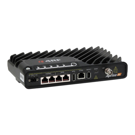
A single Aprisa SRi is configurable as a Point-To-Multipoint base station or remote radio. This guide provides a quick startup and basic installation instructions for the Aprisa SRi radio shown in the next figure below. A more detailed User Manual is also available. Refer to the User Manual for important warning, cautions and notes and any detailed management relating to fault, configuration, maintenance, performance monitoring, and security. -
Page 4: Led Display Panel
Page 4 LED Display Panel The Aprisa SRi has an LED Display panel which provides on-site alarms / diagnostics without the need for The LEDs indicate the following conditions: MODE Flashing Radio has not registered Alarm present Solid with severity... -
Page 5: Installation
The following figure shows a typical installation of the unit. The following sub-section describe the main requirements for installation. 2.1. Install the Aprisa SRi Radio and Connect the Protection Earth The Aprisa SRi has four threaded holes (M4) in the base and two holes (for M5 screws) through the enclosure for mounting. Mounting options include: •... -
Page 6: Connect The Antenna And Apply Power To The Aprisa Sri Radio
Turn your power source on. The radio LEDs will flash orange for one second and then the OK, MODE, AUX LEDs will light solid green and the TX and RX LEDs will flash red. This is because the factory default Terminal Operating Mode for all Aprisa SRi radios is set to Remote Station. -
Page 7: Connect To The Aprisa Sri Radio (Via Supervisor Or Cli)
If the IP address of the radio is unknown, it can be changed via the Command Line Interface on the radio MGMT USB port: • Connect your PC USB port to the Aprisa SRi MGMT USB port. USB to UART Bridge VCP Drivers are required to connect radio... -
Page 8: Setup The Aprisa Sri Radio
The zone frequencies are spaced at the hop frequency of 62.5 kHz. You can now configure the remaining terminal and network parameters and settings. Please refer to the Aprisa SRi User Manual for detailed instructions, such as the radio security settings and more. -
Page 9: Monitoring And Troubleshooting The Aprisa Sri Radio
4.2. Fault Management and Troubleshooting The Aprisa SRi support extensive alarms for every section and building block of the device including the interfaces. SuperVisor allows user to view the main summary alarm at the top of the SuperVisor page which mimic the device LEDs and in addition all the detailed alarms of the device (see SuperVisor >... -
Page 10: Performance Monitoring (Rf And Data Traffic)
4.3. Performance Monitoring (RF and Data Traffic) The Aprisa SRi support extensive performance monitoring statistics and diagnostic per the device and per data ports. The Aprisa SRi Terminal, Serial, Ethernet, Radio and User Selected Monitored Parameter results have history log views for both Quarter Hourly and Daily. -
Page 11: Compliance Considerations
+30 dBm The Aprisa SRi has a maximum mean output power of +26 dBm into a 50 ohm antenna which equates to a maximum peak power of +30 dBm PEP. To determine the maximum power to be set on the Aprisa SRi, the following installation parameters must be... - Page 12 Page 12 Canada This radio transmitter Aprisa SRi ISED: 6772A-SI902M160 has been approved by Industry Canada to operate with the antenna types listed below with the maximum permissible gain indicated. Antenna types not included in this list, having a gain greater than the maximum gain indicated for that type, are strictly prohibited for use with this device.
Need help?
Do you have a question about the Aprisa SRi and is the answer not in the manual?
Questions and answers