4RF Aprisa SR User Manual
Hide thumbs
Also See for Aprisa SR:
- User manual (233 pages) ,
- User manual (162 pages) ,
- Quick start manual (2 pages)

Subscribe to Our Youtube Channel
Related Manuals for 4RF Aprisa SR


Summary of Contents for 4RF Aprisa SR
- Page 1 This User Manual refers to the new Aprisa SR (part number SRx) February 2015 Version 1.3.0...
- Page 3 Copyright © 2015 4RF Limited. All rights reserved. This document is protected by copyright belonging to 4RF Limited and may not be reproduced or republished in whole or part in any form without the prior written permission of 4RF Limited.
- Page 4 / or license conditions. The term ‘Radio’ with reference to the Aprisa SR User Manual, is a generic term for one end station of a point-to-multipoint Aprisa SR network and does not confer any rights to connect to any public network or to operate the equipment within any territory.
- Page 5 Compliance Federal Communications Commission The Aprisa SR radio is designed to comply with the Federal Communications Commission (FCC) specifications as follows: Radio 47CFR part 24, part 90 and part 101 Private Land Mobile Radio Services 47CFR part 15 Radio Frequency Devices, EN 301 489 Parts 1 &...
- Page 6 WARNING: EXPLOSION HAZARD - Do not connect or disconnect while circuits are live unless area is known to be non-hazardous. The following text is printed on the Aprisa SR where the end user is in Canada: AVERTISSEMENT: RISQUE D'EXPLOSION - Ne pas brancher ou débrancher tant que le circuit est sous...
-
Page 7: Rf Exposure Warning
RF Exposure Warning WARNING: The installer and / or user of Aprisa SR radios shall ensure that a separation distance as given in the following table is maintained between the main axis of the terminal’s antenna and the body of the user or nearby persons. -
Page 9: Table Of Contents
Aprisa SR CD Contents ..............16 Software ................16 Documentation ..............16 About the Radio ............... 17 The 4RF Aprisa SR Radio ................ 17 Product Overview ................18 Network Coverage and Capacity ............18 Automatic Registration ..............18 Remote Messaging ................ 18 Store and Forward Repeater ............ - Page 10 8 | Contents Network Software Upgrade ............. 40 Test Mode ................. 41 Network Management ................42 Hardware Alarm Inputs / Outputs ............43 Alarm Input to SNMP Trap ............... 43 Alarm Input to Alarm Output ............43 Implementing the Network............44 Network Topologies ................
- Page 11 Contents | 9 Managing the Radio ..............63 SuperVisor ..................63 PC Requirements for SuperVisor ............64 Connecting to SuperVisor ............... 65 Management PC Connection ............. 66 PC Settings for SuperVisor ............67 Login to SuperVisor..............71 Logout of SuperVisor .............. 72 SuperVisor Page Layout ............
- Page 12 10 | Contents Product Options ..............266 Dual Antenna Port ................266 Full Duplex Base Station ..............266 Protected Station ................267 Protected Ports ................. 268 Operation ................268 Switch Over ..............268 Switching Criteria ............... 269 Monitored Alarms ..............270 Configuration Management ............
- Page 13 Contents | 11 11. Interface Connections ............... 296 RJ45 Connector Pin Assignments ............296 Ethernet Interface Connections ............. 296 RS-232 Serial Interface Connections ............297 Alarm Interface Connections ..............298 Protection Switch Remote Control Connections .......... 298 12. Alarm Types and Sources ............299 Alarm Types ..................
-
Page 15: Getting Started
Getting Started | 13 Getting Started This section is an overview of the steps required to commission an Aprisa SR radio network in the field: Phase 1: Pre-installation Confirm path planning. Page 48 Ensure that the site preparation is complete: Page 51 ... - Page 16 14 | Getting Started Phase 3: Establishing the link If radio’s IP address is not the default IP address (169.254.50.10 with a subnet Page 259 mask of 255.255.0.0) and you don’t know the radio’s IP address see ‘Command Line Interface’ on page 259. Connect the Ethernet cable between the radio’s Ethernet port and the PC.
-
Page 17: Introduction
Contact Us If you experience any difficulty installing or using Aprisa SR after reading this manual, please contact Customer Support or your local 4RF representative. Our area representative contact details are available from our website:... -
Page 18: Aprisa Sr Accessory Kit
Web browsers - Mozilla Firefox and Internet Explorer are included for your convenience Adobe™ Acrobat® Reader® which you need to view the PDF files on the Aprisa SR CD Documentation User manual - an electronic (PDF) version for you to view online or print ... -
Page 19: About The Radio
The radios carry a combination of serial data and Ethernet data between the base station, repeater stations and remote stations. A single Aprisa SR is configurable as a point-to-multipoint base station, a remote station or a repeater station. Aprisa SRx User Manual 1.3.0... -
Page 20: Product Overview
Product Overview Network Coverage and Capacity The Aprisa SR has a typical link range of up to 120 km, however, geographic features, such as hills, mountains, trees and foliage, or other path obstructions, such as buildings, will limit radio coverage. -
Page 21: Store And Forward Repeater
About the Radio | 19 Store and Forward Repeater The Aprisa SR in Repeater mode is used to link remote stations to the base station when direct communication is not possible due to terrain, distance, fade margin or other obstructions in the network. - Page 22 20 | About the Radio Multiple Repeater Single Hop The following example depicts an Aprisa SR multiple repeater single hop store and forward network supporting both overlapping and non-overlapping coverage repeater networks. An overlapped RF coverage area creates radio interference and might affect network performance and reduce throughput, as show in figure (a), where Remote 1 is in overlapped RF coverage with Repeater 1 and Repeater 2.
- Page 23 About the Radio | 21 Multiple Repeater Multiple Hop The following example depicts an Aprisa SR daisy chain multiple repeater multiple hop store and forward network i.e. multiple hops and multiple repeaters in non-overlapping RF coverage. The Aprisa SR daisy chain store and forward repeaters are currently supported in LBS MAC mode only.
-
Page 24: Repeater Messaging
22 | About the Radio Repeater Messaging The Aprisa SR uses a routed protocol throughout the network whereby messages contain source and destination addresses. The remote and repeater stations will register with a base station. In networks with a repeater, the repeater must register with the base station before the remotes can register with the base station. -
Page 25: Product Features
50 kHz QPSK Modulation Half duplex RF operation (full duplex provided with Aprisa SR+ in 'SR compatible' mode) Ethernet data interface and RS-232 / RS-485 asynchronous multiple port options Hardware options of dual / single antenna port options (dual antenna port for external duplexers or filters) ... -
Page 26: Security
24 | About the Radio Security The Aprisa SR provides security features to implement the key recommendations for industrial control systems. The security provided builds upon the best in class from multiple standards bodies, including: IEC/TR 62443 (TC65) ‘Industrial Communications Networks – Network and System Security’... -
Page 27: Performance
About the Radio | 25 Performance Typical deployment of 30 remote stations from one base station with a practical limit of a few hundred remote stations Long distance operation High transmit power Low noise receiver Forward Error Correction ... -
Page 28: Architecture
Remote nodes are predominantly in receive mode with only sporadic bursts of transmit data. This reduces power consumption. The Aprisa SR is a packet based radio. Data is sent over the wireless channel in discrete packets / frames, separated in time. The PHY demodulates data within these packets with coherent detection. -
Page 29: Data Link Layer / Mac Layer
Data Link Layer / MAC layer The Aprisa SR PHY enables multiple users to be able to share a single wireless channel; however a DLL is required to manage data transport. The two key components to the DLL are channel access and hop by hop transmission. -
Page 30: Network Layer
Aprisa SR router mode (see figure below), enables the routing of IP packets within the Aprisa SR wireless network and in and out to the external router / IP RTUs devices connected to the Aprisa SR wired Ethernet ports. -
Page 31: Static Ip Router
The Aprisa SR works as a static IP router without using any routing protocol and therefore does not have the overhead of a routing protocol for better utilization of the narrow bandwidth network. - Page 32 Ethernet interface’ on each radio in the network is the ‘router port’. The routing table for all directly attached devices to the Aprisa SR network, at the Base or the Remote stations is automatically built and no static routes are required to be entered for those device routes.
- Page 33 Static IP Router – Human Error Free To ensure correct operation, the Aprisa SR router base station alerts when one (or more) of the devices is not configured for router mode or a duplicated IP is detected when manually added.
-
Page 34: Bridge Mode With Vlan Aware
Ethernet VLAN Bridge / Switch Overview The Aprisa SR in Bridge mode of operation is a standard Ethernet Bridge based on IEEE 802.1d or VLAN Bridge based on IEEE 802.1q/p which forward / switch Ethernet packet based on standard MAC addresses and VLANs using FDB (forwarding database) table decisions. -
Page 35: Vlan Bridge Mode Description
VLAN management can be used to manage with external NMS all the Aprisa SR devices on the radio network and is automatically created with a VLAN ID = 1 default value. The VLAN ID can be changed by the user later on. - Page 36 VLANs carry 3 priority bits (PCP field) in the VLAN tag allowing prioritization of VLAN tagged traffic types with 8 levels of priority (where 7 is the highest priority and 0 is the lowest priority). The Aprisa SR supports QoS (Quality of Service) where the priority bits in the VLAN tagged frame are evaluated and mapped to four priority levels and four queues supported by the Aprisa SR radio.
-
Page 37: Avoiding Narrow Band Radio Traffic Overloading
SCADA traffic transmission relative to any other unimportant traffic. In this case, traffic based on VLAN priority (priority 0 to 7) enters one of the four priority queues of the Aprisa SR (Very High, High, Medium and Low). Traffic leaves the queues (to the radio network) from highest priority to lowest in a strict priority fashion. - Page 38 Robust Header Compression (ROHC) and Payload Compression Aprisa SR supports ROHC (Robust Header Compression RFC3095). ROHC is a standard way to compress IP, UDP and TCP headers and this significantly increases IP traffic throughput especially in narrow band network.
-
Page 39: Interfaces
About the Radio | 37 Interfaces Antenna Interface 2 x TNC, 50 ohm, female connectors Hardware option of single or dual antenna ports (with or without the use of external duplexer/filter) Ethernet Interface 2 ports 10/100 base-T Ethernet layer 2 switch using RJ45 Used for Ethernet user traffic and radio sub-network management. -
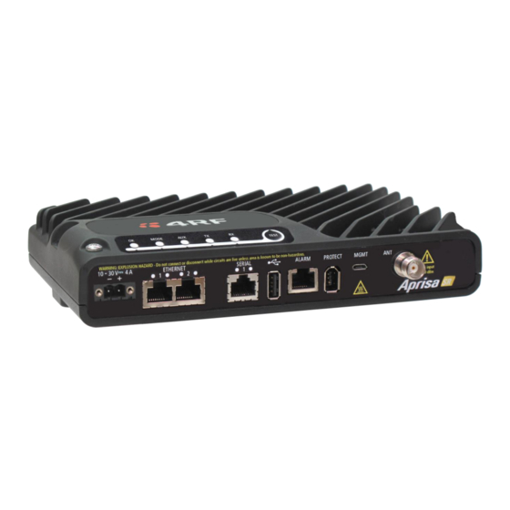
Page 40: Front Panel Connections
38 | About the Radio Front Panel Connections All connections to the radio are made on the front panel. The functions of the connectors are (from left to right): Designator Description 10 - 30 VDC; 4A +10 to +30 VDC (negative ground) DC power input using Molex 2 pin male screw fitting connector. -
Page 41: Led Display Panel
About the Radio | 39 LED Display Panel The Aprisa SR has an LED Display panel which provides on-site alarms / diagnostics without the need for Normal Operation In normal radio operation, the LEDs indicate the following conditions: MODE Flashing... -
Page 42: Single Radio Software Upgrade
40 | About the Radio Single Radio Software Upgrade During a radio software upgrade, the LEDs indicate the following conditions: Software upgrade started - the OK LED flashes orange Software upgrade progress indicated by running AUX to MODE LEDs ... -
Page 43: Test Mode
About the Radio | 41 Test Mode Remote station and repeater station radios have a Test Mode which presents a real time visual display of the RSSI on the LED Display panel. This can be used to adjust the antenna for optimum signal strength (see ‘Maintenance >... -
Page 44: Network Management
The Aprisa SR contains an embedded web server application (SuperVisor) to enable element management with any major web browser (such as Mozilla Firefox or Microsoft® Internet Explorer). SuperVisor enables operators to configure and manage the Aprisa SR base station radio and repeater / remote station radios over the radio link. -
Page 45: Hardware Alarm Inputs / Outputs
SuperVisor event history log (see ‘Events > Event History’ on page 166). These include the alarm events generated by the hardware alarm inputs. Alarm Input to SNMP Trap An alarm event from an Aprisa SR hardware alarm input can be sent over the air to any SNMP Manager using SNMP traps. Alarm Input to Alarm Output An alarm event from an Aprisa SR hardware alarm input can be mapped to an hardware alarm output of another Aprisa SR using an event action setup (see ‘Events >... -
Page 46: Implementing The Network
44 | Implementing the Network Implementing the Network Network Topologies The following are examples of typical network topologies: Point-To-Point Network Point-to-Multipoint Network Point-to-Multipoint with Repeater 1 Point-to-Multipoint with Repeater 2 Aprisa SRx User Manual 1.3.0... -
Page 47: Initial Network Deployment
Implementing the Network | 45 Initial Network Deployment Install the Base Station To install the base station in your network: 1. Install the base station radio (see ‘Installing the Radio’ on page 54). 2. Set the radio Network ID to a unique ID in your entire network (see ‘Terminal > Device’ on page 82). 3. -
Page 48: Network Changes
46 | Implementing the Network Network Changes Adding a Repeater Station To add a repeater station to your network: 1. Install the repeater station radio (see ‘Installing the Radio’ on page 54). 2. Set the radio Network ID to the same ID as the other stations in the network (see ‘Terminal > Device’ on page 82). -
Page 49: Preparation
Preparation | 47 Preparation Bench Setup Before installing the links in the field, it is recommended that you bench-test the links. A suggested setup for basic bench testing is shown below: When setting up the equipment for bench testing, note the following: Earthing Each radio should be earthed at all times. -
Page 50: Path Planning
48 | Preparation Path Planning The following factors should be considered to achieve optimum path planning: Antenna Selection and Siting Coaxial Cable Selection Linking System Plan Antenna Selection and Siting Selecting and siting antennas are important considerations in your system design. The antenna choice for the site is determined primarily by the frequency of operation and the gain required to establish reliable links. -
Page 51: Remote Station
Preparation | 49 Remote station There are two main types of directional antenna that are commonly used for remote stations, Yagi and corner reflector antennas. Yagi Antennas Factor Explanation Frequency Often used in 350-600 MHz bands Gain Varies with size (typically 11 dBi to 16 dBi) Stackable gain increase 2 Yagi antennas (+ 2.8 dB) -
Page 52: Antenna Siting
50 | Preparation Corner Reflector Antennas Factor Explanation Frequency Often used in 330-960 MHz bands Gain Typically 12 dBi Size Range from 0.36 m to 0.75 m in length Front to back ratio High (typically 30 dB) Beamwidth Broad (up to 60°) Antenna Siting When siting antennas, consider the following points: A site with a clear line of sight to the remote radio is recommended. -
Page 53: Coaxial Feeder Cables
Preparation | 51 Coaxial Feeder Cables To ensure maximum performance, it is recommended that you use good quality low-loss coaxial cable for all feeder runs. When selecting a coaxial cable consider the following: Factor Effect Attenuation Short cables and larger diameter cables have less attenuation Cost Smaller diameter cables are cheaper Ease of installation... -
Page 54: Site Requirements
DC power connection. Equipment Cooling If the Aprisa SR is operated in an environment where the ambient temperature exceeds 50°C, the Aprisa SR convection air flow over the heat sinks must be considered. The environmental operating conditions are as follows: Operating temperature -40 to +70˚... -
Page 55: Earthing And Lightning Protection
Radio Earthing The Aprisa SR has an earth connection point on the top left and the top right of the enclosure. M4 8mm pan pozi machine screws and M4 lock washers are supplied fitted to the radio. These screws can be used to earth the enclosure to a protection earth. -
Page 56: Installing The Radio
4RF does not assume any liability for failure to comply with these precautions. Mounting The Aprisa SR has four threaded holes (M4) in the enclosure base and two holes (5.2 mm) through the enclosure for mounting. Mounting options include: ... -
Page 57: Din Rail Mounting
4RF SR+ Acc, Mounting, Bracket, DIN Rail The Aprisa SR is mounted into the DIN rail mounting bracket using the four M4 threaded holes in the Aprisa SR enclosure base. Four 8 mm M4 pan pozi machine screws are supplied with the bracket. -
Page 58: Rack Shelf Mounting
Rack Shelf Mounting The Aprisa SR can be mounted on a rack mount shelf using the four M4 threaded holes in the Aprisa SR enclosure base. The following picture shows Aprisa SR mounted on a 1 RU rack mounted shelf. -
Page 59: Wall Mounting
Installing the Radio | 57 Wall Mounting The Aprisa SR can be mounted on a wall using the two holes through the enclosure (5.2 mm diameter). Typically, M5 screws longer than 35 mm would be used. Aprisa SRx User Manual 1.3.0... -
Page 60: Installing The Antenna And Feeder Cable
Connect the antenna and feeder cable. Weatherproof the connection with a boot, tape or other approved method. The Aprisa SR antenna connection is a TNC female connector so the feeder / jumper must be fitted with a TNC male connector. -
Page 61: Connecting The Power Supply
The power connector required is a Molex 2 pin female screw fitting part. This connector is supplied fitted to the radio. The negative supply of the Aprisa SR power connection is internally connected to the Aprisa SR enclosure. Power must be supplied from a Negative Earthed power supply. -
Page 62: Spare Fuses
Spare Fuses The Aprisa SR PBA contains two fuses in the power input with designators F1 and F2. Both the positive and negative power connections are fused. The fuse type is a Littelfuse 0454007 with a rating of 7 A, 125 V, very fast acting. -
Page 63: Additional Spare Fuses
Additional Spare Fuses Additional spare fuses can be ordered from 4RF: Part Number Part Description APST-FNAN-454-07-02 4RF SR+ Spare, Fuse, Nano SMF, 454 Series, 7A, 2 items Aprisa SRx User Manual 1.3.0... -
Page 65: Managing The Radio
The Aprisa SR contains an embedded web server application (SuperVisor) to enable element management with any major web browser (such as Mozilla Firefox or Microsoft® Internet Explorer). SuperVisor enables operators to configure and manage the Aprisa SR base station radio and repeater / remote station radios over the radio link. -
Page 66: Pc Requirements For Supervisor
1 GB Ram Pentium 4 and above (4RF does not support retina displays) Note: 4RF does not support Google Chrome, Opera browser or Apple Safari but when they have been used they have worked correctly. Aprisa SRx User Manual 1.3.0... -
Page 67: Connecting To Supervisor
IP networking. There should be only one Ethernet connection from the base station to the management network. The Aprisa SR has a factory default IP address of 169.254.50.10 with a subnet mask of 255.255.0.0. This is an IPv4 Link Local (RFC3927) address which simplifies the connection to a PC. -
Page 68: Management Pc Connection
66 | Managing the Radio Management PC Connection The active management PC must only have one connection to the network as shown by path . There should not be any alternate path that the active management PC can use via an alternate router or alternate LAN that would allow the management traffic to be looped as shown by path . -
Page 69: Pc Settings For Supervisor
Managing the Radio | 67 PC Settings for SuperVisor To change the PC IP address: If your PC has previously been used for other applications, you may need to change the IP address and the subnet mask settings. You will require Administrator rights on your PC to change these. Windows XP example: 1. - Page 70 68 | Managing the Radio To change the PC connection type: If your PC has previously been used with Dial-up connections, you may need to change your PC Internet Connection setting to ‘Never dial a connection’. Windows Internet Explorer 8 example: 1.
- Page 71 Managing the Radio | 69 To change the PC pop-up status: Some functions within SuperVisor require Pop-ups enabled e.g. saving a MIB Windows Internet Explorer 8 example: 1. Open Internet Explorer. 2. Open the menu item Tools > Internet Options and click on the ‘Privacy’ tab. 3.
- Page 72 70 | Managing the Radio To enable JavaScript in the web browser: Some functions within SuperVisor require JavaScript in the web browser to be enabled. Windows Internet Explorer 8 example: 1. Open Internet Explorer. 2. Open the menu item Tools > Internet Options and click on the ‘Security’ tab. 3.
-
Page 73: Login To Supervisor
‘Command Line Interface’ on page 259). Note: The Aprisa SR has a Self Signed security certificate which may cause the browser to prompt a certificate warning. It is safe to ignore the warning and continue. The valid certificate is ‘Issued By: 4RF- APRISA’... -
Page 74: Logout Of Supervisor
72 | Managing the Radio If the login is successful, the opening page will be displayed. If there is more than one user logged into the same radio, the Multiple Management Sessions popup will show the usernames and IP addresses of the users. This popup message will display until 5 seconds after the cursor is moved. -
Page 75: Supervisor Page Layout
Managing the Radio | 73 SuperVisor Page Layout Standard Radio The following shows the components of the SuperVisor page layout for a standard radio: SuperVisor Branding Bar The branding bar at the top of the SuperVisor frame shows the branding of SuperVisor on the left and the product branding on the right. - Page 76 74 | Managing the Radio SuperVisor Summary Bar The summary bar at the bottom of the page shows: Position Function Left Busy - SuperVisor is busy retrieving data from the radio that SuperVisor is logged into. Ready - SuperVisor is ready to manage the radio. Middle Displays the name of the radio terminal that SuperVisor is currently managing.
-
Page 77: Supervisor Menu
Managing the Radio | 75 SuperVisor Menu The following is a list of SuperVisor top level menu items: Local Terminal Network Network Table Terminal Summary Radio Exceptions Serial View Ethernet Security Maintenance Events Software Monitoring SuperVisor Parameter Settings Changes to parameters settings have no effect until the ‘Save’ button is clicked. Click the ‘Save’... -
Page 78: Supervisor Menu Access
76 | Managing the Radio SuperVisor Menu Access The SuperVisor menu has varying access levels dependent on the login User Privileges. The following is a list of all possible SuperVisor menu items versus user privileges: Terminal Settings Menu Items Menu Item View Technician Engineer... -
Page 79: Supervisor Menu Items
View Read-Only Read-Only Read-Only Read-Only SuperVisor Menu Items As SuperVisor screens are dependent on the Aprisa SR configuration deployed, the following section is split into two sections: Standard Radio Protected Station All SuperVisor menu item descriptions assume full access ‘Admin’ user privileges:... -
Page 80: Standard Radio
78 | Managing the Radio Standard Radio Terminal Terminal > Summary TERMINAL SUMMARY This page displays the current settings for the Terminal parameters. See ‘Terminal > Details’ on page 80, ‘Terminal > Device’ on page 82 and ‘Terminal > Operating Mode’ on page 87 for setting details. OPERATING SUMMARY Operating Mode This parameter displays the current Operating Mode i.e. - Page 81 Managing the Radio | 79 TX Frequency (MHz) This parameter displays the current Transmit Frequency in MHz. TX Power (dBm) This parameter displays the current Transmit Power in dBm. RX Frequency (MHz) This parameter displays the current Receive Frequency in MHz. Channel Size (kHz) This parameter displays the current Channel Size in kHz.
- Page 82 80 | Managing the Radio Terminal > Details MANUFACTURING DETAILS Radio Serial Number This parameter displays the Serial Number of the radio (shown on the enclosure label). Sub-Assembly Serial Number This parameter displays the Serial Number of the printed circuit board assembly (shown on the PCB label). Aprisa SRx User Manual 1.3.0...
- Page 83 Managing the Radio | 81 Hardware Variant Type This parameter displays the hardware variant radio frequency operating range. Radio MAC Address This parameter displays the MAC address of the radio (the management Ethernet MAC address). Active Software Version This parameter displays the version of the software currently operating the radio. Previous Software Version This parameter displays the software version that was running on the radio prior to the current software being activated.
- Page 84 1. Enter the Terminal Name. 2. Enter the Location of the radio. 3. Enter a Contact Name. The default value is ‘4RF Limited’. 4. Enter the Contact Details. The default value is ‘support@4RF.com’. Aprisa SRx User Manual 1.3.0...
- Page 85 Managing the Radio | 83 RF NETWORK DETAILS Network ID (network) This parameter sets the network ID of this base station node and its remote / repeater stations in the network. The entry is four hexadecimal chars (not case sensitive). The default setting is CAFE.
- Page 86 84 | Managing the Radio The Network Repeaters Proximity options are dependent on the Terminal Operating Mode and the Terminal Network Radius settings: Operating Mode Network Radius Network Repeaters Proximity Options Default Base No Repeater No Repeater Base Single Repeater Only, Overlapping Single Repeater Only Coverage, Separated Coverage Remote...
- Page 87 Managing the Radio | 85 Terminal > Date / Time TERMINAL DATE AND TIME Sets the Time and Date. This information is controlled from a software clock. Date and Time Synchronization This Date and Time Synchronization feature allows a radio to synchronize its date and time from an SNTP server.
- Page 88 86 | Managing the Radio Auto Synchronization Period (s) This parameter sets the number of seconds between the end of the last synchronization and the next synchronization attempt. The minimum period is 60 seconds. A period of 0 seconds will disable synchronization attempts.
- Page 89 Managing the Radio | 87 Terminal > Operating Mode OPERATING MODES Terminal Operating Mode The Terminal Operating Mode can be set to Base, Base Repeater, Repeater or Remote station. The default setting is Remote. Option Function Base The base station manages all traffic activity between itself, repeaters and remotes.
- Page 90 TERMINAL PROTECTION Protection Type The Protection Type defines if a radio is a stand-alone radio or part of an Aprisa SR Protected Station. The default setting is None. Option Function...
- Page 91 Managing the Radio | 89 PROTECTION MANAGEMENT IP ADDRESS Local IP Address The Local IP Address shows the IP address of this radio. Partner IP Address The Partner IP Address parameter is used to set the partner IP address if this radio is to become part of a Protected Station.
-
Page 92: Radio
90 | Managing the Radio Radio Radio > Radio Summary This page displays the current settings for the Radio parameters. See ‘Radio > Radio Setup’ and ‘Radio > Channel Setup’ for setting details. Aprisa SRx User Manual 1.3.0... - Page 93 Managing the Radio | 91 Radio > Channel Summary This page displays the current settings for the Channel parameters. See ‘Radio > Channel Setup’ for setting details. DATA COMPRESSION IP HeaderCompression Ratio See ‘IP Header Compression Ratio’ on page 102. Payload Compression Ratio The payload is compressed using level 3 QuickLZ data compression.
- Page 94 92 | Managing the Radio Radio > Radio Setup Transmit frequency, transmit power and channel size would normally be defined by a local regulatory body and licensed to a particular user. Refer to your site license details when setting these fields. TRANSMITTER / RECEIVER Important: 1.
- Page 95 Managing the Radio | 93 Single Frequency Operation The TX and RX frequencies of the base station, repeater station and all the remote stations are on the same frequency. To change the TX and RX frequencies: 1. Change the TX and RX frequencies of the remote stations operating from the repeater station to the new frequency.
- Page 96 94 | Managing the Radio Dual Frequency No Repeater The TX frequency of all the remote stations matches the RX frequency of the base station. The RX frequency of all the remote stations matches the TX frequency of the base station. To change the TX and RX frequencies: 1.
- Page 97 Managing the Radio | 95 Dual Frequency with Repeater The TX frequency of the remote stations associated with the base station matches the RX frequency of the base station. The TX frequency of the repeater station associated with the base station matches the RX frequency of the base station.
- Page 98 Informational Event (55 Terminal Unit Information) will be raised to notify the user that transmit power has been changed. Note: The Aprisa SR transmitter contains power amplifier protection which allows the antenna to be disconnected from the antenna port without product damage.
- Page 99 Managing the Radio | 97 GENERAL Channel Size (kHz) This parameter sets the Channel Size for the radio (see ‘Channel Sizes’ on page 307 for Radio Capacities). The default setting is 12.5 kHz. Antenna Port Configuration This parameter sets the Antenna Port Configuration for the radio. Option Function Single Antenna...
- Page 100 98 | Managing the Radio MODEM The Radio > Radio Setup screen Modem section is different for a base / repeater / base-repeater station and a remote station. Modem Mode This parameter sets the Modem Mode in the radio. The Modem Mode option list is dependent on the radio Hardware Variant.
- Page 101 Managing the Radio | 99 Radio > Channel Setup CHANNEL SETTINGS Access Scheme This parameter sets the Media Access Control (MAC) used by the radio for over the air communication. Option Function Access Request Channel access scheme where the base station controls the communication on the channel.
- Page 102 Each Aprisa SR radio can filter packets not destined for itself. The Packet Filtering parameter controls this functionality. In an Aprisa SR network, all communication from remote stations is destined for the base station in the Aprisa SR network communication protocol. In a repeater or base-repeater network, a remote station will send a message to the base station.
- Page 103 Managing the Radio | 101 Serial Data Stream Mode This parameter controls the traffic flow in the radio serial ports. Option Function Broadcast Serial port traffic from the network is broadcast on all serial ports on this radio. This will include the RS-232 port derived from the USB port.
- Page 104 102 | Managing the Radio DATA COMPRESSION IP Header Compression Ratio The IP Header Compression implements TCP/IP ROHC v2 (Robust Header Compression v2. RFC4995, RFC5225, RFC4996) to compress the IP header. IP header compression allows for faster point-to-point transactions, but only in a star network. IP Header Compression module comprises of two main components, compressor and decompressor.
- Page 105 It is used to prevent old, redundant packets being transmitted through the Aprisa SR network. The default setting is 1500 ms. In the case of serial poll SCADA networks such as MODBUS and IEC 60870.50.101, it is important to ensure the replies from the RTU are in the correct sequence and are not timed out replies from Master requests.
- Page 106 104 | Managing the Radio Serial Packet Time to Live (ms) This parameter sets the time a serial packet is allowed to live in the system before being dropped if it cannot be transmitted over the air. The default setting is 800 ms. Ethernet Packet Time to Live (ms) This parameter sets the time an Ethernet packet is allowed to live in the system before being dropped if it cannot be transmitted over the air.
-
Page 107: Serial
Managing the Radio | 105 Serial Serial > Summary This page displays the current settings for the serial port parameters. See ‘Serial > Port Setup’ on page 106 for configuration options. Type This parameter displays the Serial Port interface type. If the Name is USB Serial Port: Option Function... - Page 108 106 | Managing the Radio Serial > Port Setup This page provides the setup for the serial port settings. SERIAL PORTS SETTINGS Name This parameter sets the port name which can be up to 32 characters. Option Function Serial Port This is the normal RS-232 serial ports provided with the RJ45 connector.
- Page 109 This parameter sets the flow control of the serial port. The default setting is Disabled. Option Function None The Aprisa SR radio port (DCE) CTS is in a permanent ON (+ve) state. This does not go to OFF if the radio link fails. CTS-RTS CTS / RTS hardware flow control between the DTE and the Aprisa SR radio port (DCE) is enabled.
- Page 110 108 | Managing the Radio TERMINAL SERVER SETTINGS This menu item is only applicable if the serial port has an operating mode of Terminal Server. The Terminal Server operating mode provides encapsulation of serial data into an IP packet (TCP or UDP). A server connected to a base station Ethernet port can communicate with all remote station Ethernet ports and serial ports.
- Page 111 Managing the Radio | 109 Protocol This parameter sets the L4 TCP/IP or UDP/IP protocol used for terminal server operation. The default setting is TCP. Mode This parameter defines the mode of operation of the terminal server connection. The default setting is Client and Server.
-
Page 112: Ethernet
110 | Managing the Radio Ethernet Ethernet > Summary This page displays the current settings for the Ethernet port parameters and the status of the ports. See ‘Ethernet > Port Setup’ for configuration options. Aprisa SRx User Manual 1.3.0... - Page 113 Managing the Radio | 111 Ethernet > Port Setup This page provides the setup for the Ethernet ports settings. ETHERNET PORT SETTINGS Mode This parameter controls the Ethernet traffic flow. The default setting is Standard. Option Function Standard Enables Ethernet data communication over the radio link but Ethernet traffic is not switched locally between the two Ethernet ports.
- Page 114 112 | Managing the Radio Duplex This parameter controls the transmission mode of the Ethernet port. The default setting is Auto. Option Function Auto Provides auto selection of Ethernet Port duplex setting. Half Duplex The Ethernet Port is manually set to Half Duplex. Full Duplex The Ethernet Port is manually set to Full Duplex.
- Page 115 Managing the Radio | 113 Ethernet > L2 Filtering This page is only available if the Ethernet traffic option has been licensed (see ‘Maintenance > Licence’ on page 160). FILTER DETAILS L2 Filtering provides the ability to filter radio link traffic based on specified Layer 2 MAC addresses. Traffic originating from specified Source MAC Addresses destined for specified Destination MAC Addresses that meets the protocol type criteria will be transmitted over the radio link.
- Page 116 114 | Managing the Radio Example: In the screen shot, the rules are configured in the base station which controls the radio link traffic from base station to remote / repeater stations. Traffic from a device with the MAC address 00:01:50:c2:01:00 is forwarded over the radio link if it meets the criteria: ...
- Page 117 Managing the Radio | 115 Ethernet > VLAN This page is only available if the Ethernet traffic option has been licensed (see ‘Maintenance > Licence’ on page 160). VLAN PORT SETTINGS – All Ports This page specifies the parameters that relate to all Ethernet ports when working in Bridge Mode. Three parameters are global parameters for the Ethernet Bridge;...
- Page 118 116 | Managing the Radio Double Tag Egress S-VLAN Priority This parameter sets the S-VLAN egress traffic priority. The default is Priority 1 (Best Effort). Option Egress Priority High / Low Classification Priority Priority 0 Background Lowest Priority Priority 1 (Best Effort) Priority 2 (Excellent Effort) Priority 3 (Critical Applications) Priority 4 (Video)
- Page 119 (inner tagged), the frame will be discarded. If the Ingress Filtering is disabled, the Aprisa SR supports ‘Admit All Frames’ so that all frames tagged, untagged and priority-tagged-frames are allowed to pass through the Ethernet ports. The default is disabled.
- Page 120 118 | Managing the Radio If double tagging is enabled on the port, incoming frames should always be double tagged. If the incoming frame is untagged, then the PVID (port VLAN ID) is used and forwarded with the Port Ingress priority provided the PVID is configured in the Port VLAN Membership of any of the Ethernet ports.
- Page 121 Managing the Radio | 119 Egress Action This parameter sets the action taken on the frame on egress from the Ethernet port. The default is Untag and forward. Option Function Untag and forward Removes the tagged information and forwards the frame.
- Page 122 120 | Managing the Radio IP > IP Summary This page displays the current settings for the Networking IP Settings. See ‘IP > IP Setup’ for configuration options. Aprisa SRx User Manual 1.3.0...
- Page 123 Managing the Radio | 121 IP > IP Setup This page provides the setup for the IP Settings. NETWORKING IP SETTINGS IP Address Set the static IP Address of the radio (Management and Ethernet ports) assigned by your site network administrator using the standard format xxx.xxx.xxx.xxx.
- Page 124 122 | Managing the Radio RADIO INTERFACE IP SETTINGS The RF interface IP address is the address that traffic is routed to for transport over the radio link. This IP address is only used when Router Mode is selected i.e. not used in Bridge Mode. Radio Interface IP Address Set the IP Address of the RF interface using the standard format xxx.xxx.xxx.xxx.
- Page 125 Managing the Radio | 123 IP > L3 Filtering This page is only available if the Ethernet traffic option has been licensed (see ‘Maintenance > Licence’ on page 160) and Router Mode selected. It is not active in Bridge Mode (see 'Terminal > Operating Mode’ on page 87).
- Page 126 124 | Managing the Radio Source Wildcard Mask This parameter defines the mask applied to the source IP address. 0 means that it must be a match. If the source wildcard mask is set to 0.0.0.0, the complete source IP address will be evaluated for the filter criteria.
- Page 127 Managing the Radio | 125 IP > IP Routes This page is only available if the Ethernet traffic option has been licensed (see ‘Maintenance > Licence’ on page 160) and Router Mode selected. It is not valid for Bridge Mode (see 'Terminal > Operating Mode’ on page 87).
- Page 128 126 | Managing the Radio Gateway Address This parameter sets the gateway address where packets will be forwarded to. If the gateway interface is set to Ethernet Ports, the gateway address is the IP address of the device connected to the Ethernet port. ...
-
Page 129: Qos
Managing the Radio | 127 QoS > Summary This page provides a summary of the QoS Settings. See ‘QoS > Traffic Priority’ for configuration options. Aprisa SRx User Manual 1.3.0... - Page 130 The serial buffer is 20 serial packets (1 packet can be up to 512 bytes). There are four priority queues in the Aprisa SR: Very High, High, Medium and Low. Data is added to one of these queues depending on the priority setting. Data leaves the queues from highest priority to lowest: the Very High queue is emptied first, followed by High then Medium and finally Low.
- Page 131 Ethernet MTU, 1536 bytes). There are four priority queues in the Aprisa SR: Very High, High, Medium and Low. Data is added to one of these queues depending on the priority setting. Data leaves the queues from highest priority to lowest: the Very High queue is emptied first, followed by High then Medium and finally Low.
- Page 132 130 | Managing the Radio PRIORITY DEFINITIONS PCP (Priority Code Point) These settings provide priority translation / mapping between the external radio LAN VLAN priority network and the radio internal VLAN priority network, using the VLAN tagged PCP (Priority Code Point) priority field in the Ethernet/VLAN frame.
- Page 133 Managing the Radio | 131 This is done by mapping the external radio network VLAN priority to the internal radio CoS / priority using the ‘PCP priority definition’ tab. The radio support 4 queues, thus at maximum an 8 -> 4 VLAN priority / CoS mapping is done.
- Page 134 132 | Managing the Radio DSCP (Differentiated Services Code Point) These settings provide translation / mapping between the external radio IP priority network and the radio internal IP priority network, using the DSCP (DiffServ Code Point) priority field in the IP packet header. Differentiated Services (DiffServ) is a new model in which traffic is treated by routers with relative priorities based on the IPv4 type of services (ToS) field.
- Page 135 Managing the Radio | 133 This is done by mapping the external radio network DSCP priority to the internal radio CoS / priority levels using the ‘DSCP priority definition’ tab. The radio support four queues, thus at maximum a 64 -> 4 CoS / priority mapping is done.
-
Page 136: Security
134 | Managing the Radio Security Security > Summary This page displays the current settings for the Security parameters. See ‘Security > Setup’ and ‘Security > Manager’ for configuration options. Aprisa SRx User Manual 1.3.0... - Page 137 Managing the Radio | 135 Security > Setup PAYLOAD SECURITY PROFILE SETTINGS Security Profile Name This parameter enables the user to predefine a security profile with a specified name. Security Scheme This parameter sets the security scheme to one of the values in the following table: Security Level Disabled (No encryption and no Message Authentication Code) AES Encryption + CCM Authentication 128 bit...
- Page 138 136 | Managing the Radio Payload Encryption Key Type This parameter sets the Payload Encryption Key Type: Option Function Pass Phrase Use the Pass Phrase password format for standard security. Raw Hexidecimal Use the Raw Hexidecimal password format for better security.
- Page 139 Managing the Radio | 137 KEY ENCRYPTION KEY SETTINGS The Key Encryption Key provides the ability to encrypt the Payload Encryption Key so it can be safely transmitted over the radio link to remote radios. The Key Encryption Key Type, Key Encryption Key Size and Key Encryption Key must be the same on all radios in the network.
- Page 140 138 | Managing the Radio PROTOCOL SECURITY SETTING Telnet option This parameter option determines if you can manage the radio via a Telnet session. The default setting is disabled. ICMP option (Internet Control Message Protocol) This parameter option determines whether the radio will respond to a ping. The default setting is disabled.
- Page 141 Managing the Radio | 139 SNMPv3 Authentication Passphrase The SNMPv3 Authentication Passphrase can be changed via the SNMPv3 secure management protocol interface (not via SuperVisor). When viewing / managing the details of the users via SNMPv3, the standard SNMP-USER-BASED-SM-MIB interface is used. This interface can be used to change the SNMPv3 Authentication Passphrase of the users. The SNMPv3 Authentication Passphrase of a user required to be changed cannot be changed by the same user i.e.
- Page 142 140 | Managing the Radio SECURITY LEVEL SETTINGS Security Level This parameter sets the active security features. The default setting is Standard. Option Payload HTTPS SNMPv3 USB KEK Only Encryption Standard Strong SNMPv3 Context Addressing SNMPv3 is not user configurable and user can use this option with any NMS.
- Page 143 Managing the Radio | 141 Security > Users Note: You must login with ‘admin’ privileges to add, disable, delete a user or change a password. USER DETAILS Shows a list of the current users setup in the radio. ADD NEW USER To add a new user: 1.
- Page 144 142 | Managing the Radio 3. Select the User Privileges There are four pre-defined User Privilege settings to allocate access rights to users. These user privileges have associated default usernames and passwords of the same name. The default login is ‘admin’. This login has full access to all radio parameters including the ability to add and change users.
- Page 145 ACCESS CONTROL SETUP A SNMP Access Control is the IP address of the radio used by an SNMP manager or any other SNMP device to access the radio. The Aprisa SR allows access to the radio from any IP address. Read Only The default Read Only community string is public.
- Page 146 144 | Managing the Radio SNMP Manager Setup The SNMP manager community strings must be setup to access the base station and remote / repeater stations. To access the base station, a community string must be setup on the SNMP manager the same as the community string setup on the radio (see ‘Security >...
- Page 147 Managing the Radio | 145 Security > Manager CURRENT PAYLOAD SECURITY PROFILE Profile Name This parameter shows the predefined security profile active on the radio. Status This parameter displays the status of the predefined security profile on the radio (always active). PREVIOUS PAYLOAD SECURITY PROFILE Profile Name This parameter displays the security profile that was active on the radio prior to the current profile being...
- Page 148 146 | Managing the Radio Activate This parameter activates the previous security profile (restores to previous version). PREDEFINED PAYLOAD SECURITY PROFILE Profile Name This parameter displays the new security profile that could be activated on the radio or distributed to all remote radios with Security >...
- Page 149 Managing the Radio | 147 Security > Distribution REMOTE PAYLOAD SECURITY PROFILE DISTRIBUTION Predefined Profile Name This parameter displays the predefined security profile available for distribution to remote stations. Status This parameter shows if a predefined security profile is available for distribution to remote stations. Option Function Unavailable...
- Page 150 148 | Managing the Radio To distribute the payload security profile to remote stations: This process assumes that a payload security profile has been setup (see ‘Security > Setup’ on page 135). 1. Tick Start Transfer and click Apply. Note: This process could take up to 1 minute per radio depending on channel size, Ethernet Management Priority setting and the amount of customer traffic on the network.
- Page 151 Managing the Radio | 149 REMOTE PAYLOAD SECURITY PROFILE ACTIVATION When the security profile has been distributed to all the remote stations, the security profile is then activated in all the remote stations with this command. The base station will always attempt to distribute the profile successfully. This broadcast distribution has its own retry mechanism.
-
Page 152: Maintenance
150 | Managing the Radio Maintenance Maintenance > Summary This page displays the current settings for the Maintenance parameters. GENERAL Local Status Polling Period (sec) This parameter displays the rate at which SuperVisor refreshes the Local Radio alarm LED states and RSSI value. - Page 153 Managing the Radio | 151 NETWORK Node Registration Retry (sec) This parameter displays the base station poll time at startup or the remote / repeater station time between retries until registered. Base Station Announcement Period (min) This parameter displays the period between base station polls post startup. The default setting is 1440 minutes (24 hours).
- Page 154 152 | Managing the Radio LICENCE Remote Management This parameter displays if Remote Management is enabled or disabled. The default setting is enabled. Ethernet OTA (over the air) This parameter displays if Ethernet traffic is enabled or disabled. The Ethernet OTA will be enabled if the Ethernet feature licence has been purchased (see ‘Maintenance >...
- Page 155 This parameter sets the rate at which SuperVisor refreshes the Remote Radio alarm LED states and RSSI value. To avoid problems when managing Aprisa SR Networks, ensure that the Remote Polling Period is set to be longer than the Inband Management Timeout (set on page 82). The default setting is 20 seconds.
- Page 156 154 | Managing the Radio Write Alarm History to USB This parameter when enabled writes the alarm history file to a USB flash drive into the host port The file is a space delimited text file with a file name in the format ‘alarm_ipaddress_date,time’ e.g.
- Page 157 Managing the Radio | 155 REBOOT To reboot the radio: 1. Select Maintenance > General. 2. Tick the ‘Reboot’ checkbox. 3. Click ‘Save’ to apply the changes or ‘Cancel’ to restore the current value. 4. Click ‘OK’ to reboot the radio or ‘Cancel’ to abort. All the radio LEDs will flash repeatedly for 1 second.
- Page 158 156 | Managing the Radio Maintenance > Test Mode TRANSMITTER PRBS Test Enabled When active, the transmitter outputs a continuous PRBS signal. This can be used for evaluating the output spectrum of the transmitter and verifying adjacent channel power and spurious emission products. Deviation Test Enabled When active, the transmitter outputs a sideband tone at the deviation frequency used by the CPFSK modulator.
- Page 159 Managing the Radio | 157 RSSI TEST BUTTON Response Timeout (ms) This parameter sets the time RSSI Test Mode waits for a response from the base station before it times out and retries. The default setting is 3000 ms. Transmit Period (sec) This parameter sets the time between RSSI Test Mode requests to the base station.
- Page 160 158 | Managing the Radio Maintenance > Modem FEC DISABLE FEC Disable This parameter sets whether the Forward Error Correction can be disabled. Option Function Enable Enables the FEC Disable diagnostic function Disable Disables the FEC Disable diagnostic function Timer Allows the FEC to be disabled but only for a predetermined period.
- Page 161 Managing the Radio | 159 Maintenance > Defaults DEFAULTS The Maintenance Defaults page is only available for the local terminal. Restore Factory Defaults When activated, all radio parameters will be set to the factory default values. This includes resetting the radio IP address to the default of 169.254.50.10.
- Page 162 160 | Managing the Radio Maintenance > Licence LICENCE Fully Featured Radio When a fully featured Aprisa SR radio is purchased (indicated by the AA), it contains the licences which activate Remote Management, Ethernet Traffic, and SNMP Management e.g. Part Number Part Description...
- Page 163 Managing the Radio | 161 Maintenance > Advanced NETWORK Node Registration Retry (sec) This parameter sets the base station poll time at startup or the remote / repeater station time between retries until registered. The default setting is 10 seconds. Base Station Announcement Period (min) This parameter sets the period between base station polls post startup.
- Page 164 162 | Managing the Radio Node Missed Poll Count This parameter sets the number of times the base station attempts to poll the network at startup or if a duplicate IP is detected when a remote / repeater station is replaced. The default setting is 3. Discover Nodes This parameter when activated triggers the base station to poll the network with Node Missed Poll Count and Node Registration Retry values.
- Page 165 (example is Windows Internet Explorer 11). The file should be renamed to be able to identify the radio it was saved from. The ‘gz’ file is normally for sending back to 4RF Limited for analysis but can be opened with WinRar.
- Page 166 164 | Managing the Radio File - Configuration Script Action Action Option Load and Execute This loads and executes configuration script files. These are sample configuration script files on the product CD in a directory ‘Master Configuration’. The purpose of these files is to use as templates to create your own configuration scripts.
-
Page 167: Events
The Events menu contains the setup and management of the alarms, alarm events and traps. Events > Alarm Summary There are two types of events that can be generated on the Aprisa SR radio. These are: 1. Alarm Events Alarm Events are generated to indicate a problem on the radio. - Page 168 166 | Managing the Radio Events > Event History EVENT HISTORY The last 1500 events are stored in the radio. The complete event list can be downloaded to a USB flash drive (see ‘Write Alarm History to USB’ on page 154). The Event History can display the last 50 events stored in the radio in blocks of 8 events.
- Page 169 Managing the Radio | 167 Events > Events Setup EVENTS SETUP Alarm event parameters can be configured for all alarm events (see ‘Alarm Events’ on page 300). All active alarms for configured alarm events will be displayed on the Monitoring pages (see ‘Monitoring’ on page 195).
- Page 170 168 | Managing the Radio Severity The Severity parameter sets the alarm severity. Severity Function Critical The Critical severity level indicates that a service affecting condition has occurred and an immediate corrective action is required. Such a severity can be reported, for example, when a managed object becomes totally out of service and its capability must be restored.
- Page 171 Managing the Radio | 169 Switch This parameter determines if the alarm when active causes a switch over of the Protection Switch. This parameter is only applicable when the radio is part of a Protected Station. Block This parameter determines if the alarm is prevented from causing a switch over of the Protection Switch. This parameter is only applicable when the radio is part of a Protected Station.
- Page 172 170 | Managing the Radio Events > Traps Setup TRAPS SETUP All events can generate SNMP traps. The types of traps that are supported are defined in the ‘Notification Mode’. Destination Address This parameter sets the IP address of the server running the SNMP manager. Port This parameter sets the port number the server running the SNMP manager.
- Page 173 Managing the Radio | 171 Notification Type This parameter sets the type of event notification: Option Function Standard Trap Provides a standard SNMP trap event Inform Request Provides a SNMP v2 Inform Request trap event including trap retry and acknowledgement Notification Type set to Inform Request: Timeout (second) This parameter sets the time interval to wait for an acknowledgement before sending another retry.
- Page 174 172 | Managing the Radio Events > Alarm I/O Setup ALARM PORTS This page provides control of the two hardware alarm inputs and two hardware alarm outputs provided on the alarm connector. The alarm inputs are used to transport alarms to the other radios in the network. The alarm outputs are used to receive alarms from other radios in the network.
- Page 175 Managing the Radio | 173 Active State The Active State parameter sets the alarm state when the alarm is active. Alarm Input Option Function The alarm is active low i.e. a ground contact on the port will cause an active alarm state High The alarm is active high i.e.
- Page 176 174 | Managing the Radio Events > Event Action Setup EVENT ACTION SETUP This page provides control of the mapping of events to specific actions. Specific alarm events can setup to trigger outputs. Action Definition This parameter shows the number of the event action setup and the maximum number of setups stored. Action Destination IP Address This parameter sets the IP address of the radio that will output the action type.
- Page 177 Managing the Radio | 175 Action Threshold Criteria This parameter sets the radio event that will trigger the action output. Option Function None No action output. Radio Severity Equal Critical Activates the action output when a radio alarm is critical alarm Radio Severity Equal Major Activates the action output when a radio alarm is a major...
- Page 178 176 | Managing the Radio Events > Defaults EVENT DEFAULTS Restore Defaults This parameter when activated restores all previously configured event parameters using ‘Events > Events Setup’ to the factory default settings. Aprisa SRx User Manual 1.3.0...
-
Page 179: Software
Network Software Upgrade The radio software can be upgraded on an entire Aprisa SR radio network remotely over the radio link (see ‘Network Software Upgrade’ on page 292). This process involves following steps: 1. Transfer the new software to base station with ‘Software > File Transfer’... - Page 180 178 | Managing the Radio Software > Summary This page provides a summary of the software versions installed on the radio, the setup options and the status of the File Transfer. Aprisa SRx User Manual 1.3.0...
- Page 181 Managing the Radio | 179 SOFTWARE VERSIONS Current Version This parameter displays the software version running on the radio. Previous Version This parameter displays the software version that was running on the radio prior to the current software being activated. Software Pack Version On the base station, this parameter displays the software version available for distribution to all radios in the network.
- Page 182 Load Only New software will be uploaded from a USB flash drive in to the Aprisa SR when the radio is power cycled. The software will need to be manually activated (see ‘Software > Manager’ on page 184). Disabled Software will not be uploaded from a USB flash drive into the Aprisa SR when the radio is power cycled.
- Page 183 Managing the Radio | 181 Software > File Transfer This page provides the mechanism to transfer new software from a file source into the radio. SETUP FILE TRANSFER Direction This parameter sets the direction of file transfer. In this software version, the only choice is ‘To the Radio’.
- Page 184 File Error The transfer has failed. Possible causes of failure are: Is the source file available e.g. USB flash drive plugged in Does the file source contain the Aprisa SR software release files; Aprisa SRx User Manual 1.3.0...
- Page 185 Managing the Radio | 183 To transfer software into the Aprisa SR radio: USB Transfer Method 1. Unzip the software release files in to the root directory of a USB flash drive. 2. Insert the USB flash drive into the host port 3.
- Page 186 184 | Managing the Radio Software > Manager This page summarises and manages the software versions available in the radio. The manager is predominantly used to activate new software on single radios. Network activation is performed with ‘Software > Remote Activation’. Both the previous software (if available) and Software Pack versions can be activated on the radio from this page.
- Page 187 The software is not operating the radio but could be re-activated if required. Activate This parameter activates the previous software version (restores to previous version). The Aprisa SR will automatically reboot after activation. SOFTWARE PACK Version This parameter displays the software pack version available for distribution on base station and activate on all stations.
- Page 188 186 | Managing the Radio Activation Date & Time This parameter sets the Date & Time when the software pack activation will occur. This setting can be any future date and 24 hour time. If the network base station radio date / time is not synchronized, you will get the following popup: You can manually enter the base station radio date / time or use the Date And Time Synchronization from a SNTP server feature (see ‘Terminal >...
- Page 189 Managing the Radio | 187 To activate a software version: 1. Tick the software version required to be activated (previous software or software pack). 2. Click ‘Apply’. The page will display a Status of ‘Activating’. Once started, activation cannot be cancelled. When the activation is completed, the radio will reboot.
- Page 190 188 | Managing the Radio Software > Remote Distribution This page provides the mechanism to distribute software to all remote stations into the Aprisa SR network (network) and then activate it. The Software Pack that was loaded into the base station with the file transfer process (see ‘Software >...
- Page 191 Managing the Radio | 189 Start Transfer This parameter when activated distributes (broadcasts) the new Software Pack to all remote stations in the network. Note: The distribution of software to remote stations does not stop customer traffic from being transferred. However, due to the volume of traffic, the software distribution process may affect customer traffic.
- Page 192 190 | Managing the Radio Software > Remote Activation This page provides the mechanism to activate software on all remote stations. The Software Pack was loaded into the base station with the file transfer process (see ‘Software > File Transfer’ on page 181) and was distributed via the radio link to all remote stations. This page is used to manage the activation of that software pack on all remote radios on the network.
- Page 193 Managing the Radio | 191 Activation Date & Time This parameter sets the Date & Time when the software pack activation will occur. This setting can be any future date and 24 hour time. Skip Confirmation Step This parameter when enabled skips the confirmation step during the activation process. Normally, the confirmation step will require use intervention to accept the confirmation which will halt the activation process.
- Page 194 192 | Managing the Radio The remote stations will be polled to determine which radios require activation: Result Function (X of Y) Remote Radios Polled for X is the number of radios polled to determine the number of Partners protected stations in the network. Y is the number of remote radios registered with the base station.
- Page 195 Managing the Radio | 193 The page will display the progress of the activation. The example shows that during the activation process there were exceptions that may need to be investigated. When all the remote radios have been activated, the base station radio must now be activated with (see ‘Software >...
- Page 196 194 | Managing the Radio Activation Type This parameter sets when the remote software activation will occur. Option Function Activates the remote software now. Date & Time Activates the remote software at the Date & Time set in the following parameter. Skip Confirmation Step This parameter when enabled skips the confirmation step during the activation process.
-
Page 197: Monitoring
Managing the Radio | 195 Monitoring Monitoring > Terminal This page displays the current radio internal and external input source radio power supply voltage diagnostic parameters. The results shown are since the page was opened and are updated automatically every 12 seconds. Aprisa SRx User Manual 1.3.0... - Page 198 196 | Managing the Radio Monitoring > Serial This page displays the current radio performance monitoring parameters per serial port in packet and byte level granularity, for serial port high level statistics and troubleshooting. The results shown are since the page was opened and are updated automatically every 12 seconds. Controls The Reset button clears the current results.
- Page 199 Managing the Radio | 197 Monitoring > Ethernet This page displays the current radio performance monitoring parameters per Ethernet port transmission (TX) out of the radio in packet and byte level granularity, for Ethernet port high level statistics and troubleshooting. The results shown are since the page was opened and are updated automatically every 12 seconds.
- Page 200 198 | Managing the Radio This page displays the current radio performance monitoring parameters per Ethernet port received (RX) data in packet and byte level granularity, for Ethernet port high level statistics and troubleshooting. The results shown are since the page was opened and are updated automatically every 12 seconds. Controls The Reset button clears the current results.
- Page 201 Managing the Radio | 199 Monitoring > Radio This page displays the current radio diagnostic and performance monitoring parameters of the radio transmitter. The results shown are since the page was opened and are updated automatically every 12 seconds. Controls The Reset button clears the current results.
- Page 202 200 | Managing the Radio This page displays the current radio performance monitoring parameters of radio receiver. The results shown are since the page was opened and are updated automatically every 12 seconds. Controls The Reset button clears the current results. Aprisa SRx User Manual 1.3.0...
- Page 203 Managing the Radio | 201 This page displays the current radio RF transmit path modulation setting to single or multiple destination radios that the radio is transmitting to. The results shown are since the page was opened and are updated automatically every 12 seconds. RADIO PARAMETERS Result Function...
- Page 204 202 | Managing the Radio This page displays the current radio RF receive path parameters from single or multiple source radios that the radio is receiving from. The results shown are since the page was opened and are updated automatically every 12 seconds. RADIO PARAMETERS Result Function...
- Page 205 Managing the Radio | 203 Monitoring > User Selected This page displays the ‘User’ parameters setup in all the other Monitoring screens e.g. in the Monitoring > Radio > Transmitter, the User checkbox is ticked for the Dropped Packets (Congestion) and Dropped Bytes (Congestion).
- Page 206 204 | Managing the Radio Monitoring > TCP Connections This page displays the list of active TCP connections on the radio. TCP CONNECTIONS TABLE The Next button will display the next page of 8 connections and the Prev button will display the previous page of 8 connections.
- Page 207 Managing the Radio | 205 Monitoring > Routing Table This page displays the list of active routes on the radio. ROUTING TABLE Controls The Next button will display the next page of 8 routes and the Prev button will display the previous page of 8 routes.
- Page 208 206 | Managing the Radio Monitoring > Address Tables ARP Table This page displays the current Address Resolution Protocols (ARP) on the radio. The radio implemented ARP protocol is used for resolution of network layer addresses into link layer addresses. It is used to map a IPv4 address to an Ethernet MAC address.
- Page 209 Managing the Radio | 207 Ethernet MAC Learning Table This page displays the current Ethernet Media Access Control (MAC) Address table on the radio LAN network. In order for the radio to switch frames between Ethernet LAN ports efficiently, the radio layer 2 bridge maintains a MAC address table.
-
Page 210: Network Status
208 | Managing the Radio Network Status Network Status > Network Table This page displays a list of all the registered remote stations for the base station and provides management access to each of the remote stations. NETWORK TABLE This Network Table is only available when the local radio is the base station i.e. SuperVisor is logged into the base station. - Page 211 Managing the Radio | 209 Network Status > Summary Network View is an overview of the health of the network providing the ability to investigate issues directly within SuperVisor. This page provides an overall summary view of the alarm status of all registered remote stations for the base station.
- Page 212 210 | Managing the Radio NETWORK SUMMARY A network poll will start when any of the Network Status pages are opened (Summary, Exceptions or View). The network poll will only continue to poll the remote stations if one of the Network Status pages is open (SuperVisor can lose PC focus).
- Page 213 Managing the Radio | 211 Network Status > Exceptions This page provides a list of all registered remote radios that are in an alarmed state or have stopped responding to the SuperVisor polling. When open, it provides a continuous monitor of the network. NETWORK EXCEPTIONS A network poll will start when any of the Network Status pages are opened (Summary, Exceptions or View).
- Page 214 212 | Managing the Radio If a remote radio does not respond to a poll request within 10 seconds, the previous readings from that radio will be presented. Connectivity to a remote radio will be show as ‘lost’ if the remote radio has not responded to 3 consecutive poll requests.
- Page 215 Managing the Radio | 213 Network Status > View This page provides a complete list of all registered remote radios. It is similar to the Exceptions page but it shows all radios, not limited to the radios with alarms. When open, it provides a continuous monitor of the network.
- Page 216 214 | Managing the Radio If a remote radio does not respond to a poll request within 10 seconds, the previous readings from that radio will be presented. Connectivity to a remote radio will be show as ‘lost’ if the remote radio has not responded to 3 consecutive poll requests.
-
Page 217: Protected Station
Aprisa SRx radios. The ‘SR Compatible’ option must be enabled on the Aprisa SR+ Protected Station radios (see ‘SR+ Compatible’ on page 220). The majority of SuperVisor screens are the same for the standard Aprisa SR+ radio and the Aprisa SR+ protected station. The following screens are specific to the protected station. -
Page 218: Terminal
Aprisa SR radios. This feature is a future development. Monitored Hot Standby The RF ports and interface ports from two standard Aprisa SR (Protected Station) radios are switched to the standby radio if there is a failure in the active radio. - Page 219 Managing the Radio | 217 Switch Count This parameter shows the number of protection switch-overs since the last radio reboot (volatile). Primary Address This parameter shows the IP address of the primary radio (usually the left side radio A). Secondary Address This parameter shows the IP address of the secondary radio (usually the right side radio B).
- Page 220 218 | Managing the Radio Protected Station: Terminal > Details PRIMARY UNIT / SECONDARY UNIT MANUFACTURING DETAILS See ‘Terminal > Details’ on page 80 for parameter settings. Aprisa SRx User Manual 1.3.0...
- Page 221 Managing the Radio | 219 Protected Station: Terminal > Operating Mode OPERATING MODES Terminal Operating Mode The Terminal Operating Mode can be set to Base, Base Repeater, Repeater or Remote station. The default setting is Remote. Option Function Base The base station manages all traffic activity between itself, repeaters and remotes.
- Page 222 Aprisa SR modulation) and disables functionality which is not available in Aprisa SR for full compatibility / interoperability operation. Note: Any mix between Aprisa SR+ and Aprisa SR in the network will force the whole network to work in SR Compatible mode.
- Page 223 Managing the Radio | 221 TERMINAL PROTECTION Protection Type The Protection Type defines if a radio is a stand-alone radio or part of an Aprisa SR Protected Station. The default setting is None. Option Function None The Aprisa SR radio is a stand-alone radio (not part of an Aprisa SR Protected Station).
- Page 224 222 | Managing the Radio Protected Station: Terminal > TCP Connections The TCP Connections page displays the list of active TCP connections on the radio. PRIMARY / SECONDARY TCP CONNECTIONS TABLE The Next button will display the next page of 8 connections and the Prev button will display the previous page of 8 connections.
- Page 225 Managing the Radio | 223 Protected Station: Terminal > Routing Table The Routing Table page displays the list of active routes on the radio. ROUTING TABLE The Next button will display the next page of 8 routes and the Prev button will display the previous page of 8 routes.
- Page 226 224 | Managing the Radio Protected Station: Radio > Radio Setup Transmit frequency, transmit power and channel size would normally be defined by a local regulatory body and licensed to a particular user. Refer to your site license details when setting these fields. Antenna Port Configuration This parameter sets the Antenna Port Configuration for the radio.
- Page 227 Managing the Radio | 225 Dual Antenna Dual Select Dual Antenna Dual Port for a dual antenna protected station Port (duplexer) using: (1) One or two frequency in half duplex transmission with two external duplexer (for filtering) connected to the A and B ANT/TX and RX antenna ports and single antenna connected to the duplexer.
-
Page 228: Ethernet
226 | Managing the Radio Ethernet Protected Station: Ethernet > Summary This page displays the current settings for the Protected Station Ethernet port parameters. See ‘Ethernet > Port Setup’ for configuration options. Aprisa SRx User Manual 1.3.0... - Page 229 Managing the Radio | 227 Protected Station: IP > IP Summary This page displays the current settings for the Protected Station Networking IP settings. See ‘IP > IP Setup’ for configuration options. Aprisa SRx User Manual 1.3.0...
- Page 230 228 | Managing the Radio Protected Station: IP > IP Setup This page provides the setup for the Protected Station Networking IP setup. NETWORKING IP SETTINGS Changes in these parameters are automatically changed in the partner radio. Primary IP Address Set the static IP Address of the primary radio assigned by your site network administrator using the standard format xxx.xxx.xxx.xxx.
- Page 231 Managing the Radio | 229 Protected Station Virtual IP Address (PVIP) The Protected Station Virtual IP Address (PVIP) is the IP Address of the active radio whether it is the primary radio or the secondary radio. The PVIP is available in both bridge and router modes. In router mode, the PVIP can be used as ‘next hop’...
- Page 232 230 | Managing the Radio RADIO INTERFACE IP SETTINGS The RF interface IP address is the address that traffic is routed to for transport over the radio link. This IP address is only used when Router Mode is selected i.e. not used in Bridge Mode. Radio Interface IP Address Set the IP Address of the RF interface using the standard format xxx.xxx.xxx.xxx.
-
Page 233: Security
Managing the Radio | 231 Security Protected Station: Security > Setup This page displays the current settings for the Security parameters. KEY ENCRYPTION KEY SETTINGS USB Transaction Status This parameter shows if a USB flash drive is plugged into the radio host port Option Function USB Storage Disconnected A USB flash drive is not plugged into the radio host port. - Page 234 232 | Managing the Radio Protected Station: Security > Manager This page provides the management and control of the Protected Station Networking Security settings. PRIMARY / SECONDARY SECURITY PROFILE See ‘Security > Manager’ on page 145 for parameter details. Aprisa SRx User Manual 1.3.0...
-
Page 235: Maintenance
Managing the Radio | 233 Maintenance Protected Station: Maintenance > General This page provides the management and control of the Protected Station Maintenance General settings. See ‘Maintenance > General’ on page 153 for parameter details. Aprisa SRx User Manual 1.3.0... - Page 236 234 | Managing the Radio Protected Station: Maintenance > Protection This page provides the management and control of the Protected Station Maintenance Protection settings. SOFTWARE MANUAL LOCK The software Manual Lock is a software implementation of the Hardware Manual Lock switch on the Protection Switch.
- Page 237 Managing the Radio | 235 CURRENT PROTECTION INFORMATION Switch Control This parameter shows the status of the switch control i.e. which mechanism is in control of the protection switch. Option Function Automatic The protection is automatic and switching will be governed by normal switching and blocking criteria.
- Page 238 236 | Managing the Radio COPY CONFIGURATION When common parameters are changed in one radio, they are automatically changed in the partner radio but if one radio has been replaced in the protected station, common parameters will need to be updated in the new radio.
- Page 239 Managing the Radio | 237 Protected Station: Maintenance > Licence This page provides the management and control of the Protected Station Maintenance Licence settings. PRIMARY / SECONDARY LICENCE See ‘Maintenance > Licence’ on page 160 for parameter details. Aprisa SRx User Manual 1.3.0...
- Page 240 238 | Managing the Radio Protected Station: Maintenance > Advanced This page provides the management and control of the Protected Station Maintenance Advanced settings. NETWORK See ‘Maintenance > Advanced’ on page 161 for parameter details. RF Interface MAC address This parameter is only applicable when the radio is part of a Protected Station. This RF Interface MAC address is used to define the MAC address of the Protection Switch.
- Page 241 Managing the Radio | 239 PRIMARY / SECONDARY CONFIGURATION See ‘Maintenance > Advanced’ on page 161 for parameter details. PRIMARY / SECONDARY MAINTENANCE FILES See ‘Maintenance > Advanced’ on page 161 for parameter details. Aprisa SRx User Manual 1.3.0...
-
Page 242: Events
The Events menu contains the setup and management of the alarms, alarm events and traps. Protected Station: Events > Alarm Summary There are two types of events that can be generated on the Aprisa SR radio. These are: 1. Alarm Events Alarm Events are generated to indicate a problem on the radio. - Page 243 Managing the Radio | 241 Protected Station: Events > Primary History PRIMARY EVENT HISTORY See ‘Events > Event History’ on page 166 for parameter details. Aprisa SRx User Manual 1.3.0...
- Page 244 242 | Managing the Radio Protected Station: Events > Secondary History SECONDARY EVENT HISTORY See ‘Events > Event History’ on page 166 for parameter details. Aprisa SRx User Manual 1.3.0...
-
Page 245: Software
Network Software Upgrade The radio software can be upgraded on an entire Aprisa SR radio network remotely over the radio link (see ‘Network Software Upgrade’ on page 292). This process involves the following steps: 1. Transfer the new software to base station primary radio with ‘Protected Station: Software > Primary File Transfer’. - Page 246 244 | Managing the Radio Protected Station: Software > Summary This page provides a summary of the software versions installed on the radio, the setup options and the status of the File Transfers. PRIMARY / SECONDARY SOFTWARE VERSIONS See ‘Protected Station: Software > Primary File Transfer’ and ‘Protected Station: Software > Secondary File Transfer’...
- Page 247 Managing the Radio | 245 Protected Station: Software > Primary File Transfer This page provides the mechanism to transfer new software from a file source into the primary radio. SETUP FILE TRANSFER FOR PRIMARY UNIT Direction This parameter sets the direction of file transfer. In this software version, the only choice is ‘To Primary Radio’.
- Page 248 246 | Managing the Radio To transfer software into the Aprisa SR primary radio: Primary USB Transfer Method 1. Unzip the software release files in to the root directory of a USB flash drive. 2. Insert the USB flash drive into the primary radio host port 3.
- Page 249 Managing the Radio | 247 Transfer from Secondary Unit 1. Select Transfer from Secondary Unit. 2. Click on ‘Start Transfer’. 3. Go to ‘Protected Station: Software > Manager’ on page 251 to activate the Software Pack. The radio will reboot automatically. If the file transfer fails, check the Event History page (see ‘Protected Station: Events >...
- Page 250 248 | Managing the Radio Protected Station: Software > Secondary File Transfer This page provides the mechanism to transfer new software from a file source into the secondary radio. SETUP FILE TRANSFER FOR SECONDARY UNIT Direction This parameter sets the direction of file transfer. In this software version, the only choice is ‘To Secondary Radio’.
- Page 251 Managing the Radio | 249 To transfer software into the Aprisa SR secondary radio: Secondary USB Transfer Method 1. Unzip the software release files in to the root directory of a USB flash drive. 2. Insert the USB flash drive into the secondary radio host port 3.
- Page 252 250 | Managing the Radio Transfer from Primary Unit 1. Select Transfer from Primary Unit. 2. Click on ‘Start Transfer’. 3. Go to ‘Protected Station: Software > Manager’ on page 251 to activate the Software Pack. The radio will reboot automatically. If the file transfer fails, check the Event History page (see ‘Protected Station: Events >...
- Page 253 Managing the Radio | 251 Protected Station: Software > Manager This page summaries and manages the software versions available in the primary and secondary radios. The manager is predominantly used to activate new software on single radios. Network activation is performed with ‘Protected Station: Software >...
- Page 254 252 | Managing the Radio PRIMARY / SECONDARY SOFTWARE PACK Version This parameter displays the software pack version available for distribution on base station and activate on all stations. Status This parameter displays the status of the software pack version. Option Function Available...
- Page 255 Managing the Radio | 253 Protected Station: Software > Remote Distribution This page provides the mechanism to distribute software to all remote protected stations into the Aprisa SR network (network) and then activate it. The Software Pack loaded into the base station with the file transfer process (see ‘Protected Station: Software >...
- Page 256 254 | Managing the Radio Start Transfer This parameter when activated distributes (broadcasts) the new Software Pack to all remote stations in the network. Note: The distribution of software to remote stations does not stop customer traffic from being transferred. However, due to the volume of traffic, the software distribution process may affect customer traffic.
- Page 257 Managing the Radio | 255 Pause Transfer This parameter when activated, pauses the Over the Air Transfer Process and shows the distribution status. The distribution process will continue from where it was paused with Resume Transfer. Cancel Transfer This parameter when activated, cancels the Over the Air Transfer Process immediately. During the distribution process, it is possible to navigate away from this page and come back to it to check progress.
- Page 258 256 | Managing the Radio Protected Station: Software > Remote Activation This page provides the mechanism to activate software on all remote protected stations. The Software Pack has been loaded into the base station with the file transfer process (see ‘Protected Station: Software >...
- Page 259 Managing the Radio | 257 To activate software in remote stations: This process assumes that a Software Pack has been loaded into the base station with the file transfer process (see ‘Software > File Transfer’ on page 181) and that distributed to all remote radios in the network.
- Page 260 258 | Managing the Radio When the activation is ready to start: 3. Click on ‘OK’ to start the activation process or Cancel to quit. The page will display the progress of the activation. The example shows that during the activation process there were exceptions that may need to be investigated.
-
Page 261: Command Line Interface
Managing the Radio | 259 Command Line Interface The Aprisa SR has a Command Line Interface (CLI) which provides basic product setup and configuration. This can be useful if you need to confirm the radio’s IP address, for example. You can password-protect the Command Line Interface to prevent unauthorized users from modifying radio settings. - Page 262 Bridge’ (COM3 in the example below) 6. Open HyperTerminal Session (Start > All Programs > Accessories > Communications > HyperTerminal) 7. Enter a name for the connection (Aprisa SR CLI for example) and click OK. Aprisa SRx User Manual 1.3.0...
- Page 263 10. Click OK. The HyperTerminal window will open. 11. Press the Enter key to initiate the session. 12. Login to the Aprisa SR CLI with a default Username ‘admin’ and Password ‘admin’. The Aprisa SR CLI menu is shown: Aprisa SRx User Manual 1.3.0...
-
Page 264: Cli Commands
262 | Managing the Radio CLI Commands To enter a CLI command: 1. Type the first few characters of the command and hit Tab. This auto completes the command. 2. Enter the command string and enter. Note: All CLI commands are case sensitive. The top level CLI command list is displayed by typing a ? at the command prompt. -
Page 265: Viewing The Cli Terminal Summary
Managing the Radio | 263 Viewing the CLI Terminal Summary At the command prompt, type: cd APRISASR-MIB-4RF MPA APRISASR-MIB-4RF >>ls Terminal Changing the Radio IP Address with the CLI At the command prompt, type ‘set termEthController1IpAddress xxx.xxx.xxx.xxx’ Aprisa SRx User Manual 1.3.0... -
Page 266: In-Service Commissioning
264 | In-Service Commissioning In-Service Commissioning Before You Start When you have finished installing the hardware, RF and the traffic interface cabling, the system is ready to be commissioned. Commissioning the radio is a simple process and consists of: 1. Powering up the radios. 2. -
Page 267: Antenna Alignment
In-Service Commissioning | 265 Antenna Alignment A base station omni-directional collinear antenna has a vertical polarization. The remote station yagi antennas must also have vertical polarization. Aligning the Antennas Align the remote station yagi antennas by making small adjustments while monitoring the RSSI. The Aprisa SR has a Test Mode which presents a real time visual display of the RSSI on the front panel LEDs. -
Page 268: Product Options
Product Options Dual Antenna Port The standard Aprisa SR uses a one or two frequency ½ duplex transmission mode which eliminates the need for a duplexer. However, a dual antenna port option is available for separate transmit and receive antenna connection to support external duplexers or filters. The transmission remains half duplex. -
Page 269: Protected Station
The Aprisa SR+ Protected Station is fully monitored hot-standby and fully hot-swappable product providing radio and user interface protection for Aprisa SR+ radios. The RF ports and interface ports from the active radio are switched to the standby radio if there is a failure in the active radio. -
Page 270: Protected Ports
268 | Product Options Protected Ports The protected ports are located on the protected station front panel. Switching occurs between the active radio ports and the standby radio ports based on the switching criteria described below. The protected ports include: ... -
Page 271: Switching Criteria
Product Options | 269 Switching Criteria The Protected Station will switch-over operation from the active to the standby radio if any of the configurable alarm events occur, or if there is a loss of the ‘keep alive’ signal from the active radio. It is possible to configure the alarm events which will trigger the switch-over. -
Page 272: Monitored Alarms
270 | Product Options Monitored Alarms The following alarms are monitored by default on the active / standby radio. The monitored alarms are dependent on the Protection Type selected. All Protection Protection Type Redundant Monitored Hot Standby Types Monitored on Monitored on Monitored on Monitored on... -
Page 273: Configuration Management
Product Options | 271 All Protection Protection Type Redundant Monitored Hot Standby Types Monitored on Monitored on Monitored on Monitored on Alarm Type Active Radio Standby Radio Standby Radio TX Standby Radio RX 7.2 Volts Power Supply ... -
Page 274: Hardware Manual Lock
272 | Product Options Hardware Manual Lock The Hardware Manual Lock switch on the Protection Switch provides a manual override of the active / standby radio. When this lock is activated, the selected radio (A or B) becomes the active radio regardless of the Software Manual Lock and the current switching or block criteria. -
Page 275: L2 / L3 Protection Operation
/ ARP tables of upstream bridge/router for appropriate traffic flow. Hot-Swappable The two Aprisa SR+ radios are mounted on a pull-out tray to making it possible to replace a failed radio without interrupting user traffic. Aprisa SRx User Manual 1.3.0... -
Page 276: Antenna And Duplexer Options
Option 2 - single antenna with a single duplexer In this configuration, a single antenna is used with a duplexer which is connected to the Aprisa SR+ Protected Station TX/ANT and RX (A/B side) TNC ports on the front panel. In this option, the Protected Station can operate in: ... - Page 277 In this configuration, antenna redundancy is supported with dual antennas connected via dual duplexers to the Aprisa SR+ Protected Station TX/ANT and RX (A/B side) TNC ports and TX/ANT and RX (B side) TNC ports on the front panel. In this option, the Protected Station can operate in: ...
-
Page 278: Installation
276 | Product Options Installation Mounting The Aprisa SR+ Protected Station is designed to mount in a standard 19 inch rack. Aprisa SRx User Manual 1.3.0... -
Page 279: Cabling
Product Options | 277 Cabling The Aprisa SR+ Protected Station is delivered pre-cabled with power, interface, management and RF cables. There are two options for the pre-cabled Protected Station (see ‘Antenna and Duplexer Options’): 1. Standard Protected Station- suitable for options #1 and #2 (single antenna operation) - Page 280 278 | Product Options Users can change an existing Protected Station from one option to the other option by following the procedure: To change a pre-cabled Protected Station from one option to the other option: 1. Disconnect the power supply, antenna/s, interface cables and any other connections 2.
-
Page 281: Power
The protection switch is powered from the A power input or the B power input (whichever is available). The maximum combined power consumption is 35 Watts. The Aprisa SR+ Protected station has two DC power options, 12 VDC and 48 VDC. 12 VDC The 13.8 VDC nominal external power source can operate over the voltage range of +10.5 to +30 V DC... -
Page 282: Maintenance
The Protected Station software upgrade can be achieved without disruption to traffic. Network Software Upgrade This process allows customers to upgrade their Aprisa SR network from the central base station location without need for visiting remote sites. The Software Pack is loaded into the base station with the file transfer process (see ‘Software > File Transfer’... -
Page 283: Creating A Protected Station
Redundant operation. The following process will not be required. This process is to create a protected station from two individual Aprisa SR+ radios and a new spare Aprisa SR+ Protection Switch. It assumes that the Aprisa SR+ radios are currently setup for non-protected operation. -
Page 284: Replacing A Faulty Power Supply
If the B power supply is faulty, ensure that the A radio is active (whether it be the primary or secondary radio). 2. Replace the faulty power supply. Spares The Aprisa SR Protection Switch is available as spare parts for the three radio interface port options: Part Number Part Description APST-XPSW-X22... -
Page 285: Duplexer Kits
Product Options | 283 Duplexer Kits The Aprisa SR product range contains Duplexer Kit accessories for use with the Dual Antenna port Aprisa SR radios. Radio Duplexer Kits Example of part number: APSB-KDUP-400-B1-BR Part Number Description Aprisa SR+ Duplexer Kit for a SR+ Radio containing: 1x 1U 19"... - Page 286 284 | Product Options Part Number Description Aprisa SR+ Duplexer Kit for a SR+ radio containing: 1x 1U 19" rack front mount shelf with duplexer mounting brackets and APSB-KDUP-928-G0-BR screws to mount 1x SR+ radio and 1x duplexer 1x G0 Duplexer 900 MHz, s 40 MHz, p 7 MHz...
-
Page 287: Protected Station Duplexer Kits
1x A1 Duplexer 300 MHz, s 5 MHz, p 0.5 MHz 2x right angle TNC to SMA right angle 640mm cables Aprisa SR+ Duplexer Kit for a dual antenna Aprisa SR+ Protected Station containing: 1x 1U 19" rack front mount shelf with duplexer mounting brackets and... - Page 288 1x M0 Duplexer 450 MHz, s 5 MHz, p 0.5 MHz 2x right angle TNC to SMA right angle 640mm cables Aprisa SR+ Duplexer Kit for a dual antenna SR+ Protected Station containing: 1x 1U 19" rack front mount shelf with duplexer mounting brackets and...
- Page 289 Product Options | 287 Part Number Description Aprisa SR+ Duplexer Kit for a SR+ Protected Station containing: 1x 2U 19" rack front mount shelf with duplexer mounting brackets and APSB-KDUP-928-G3-PS screws 1x G3 Duplexer 900 MHz, s5.5 MHz, p0.5 MHz 2x TNC to SMA right angle 640mm cables Aprisa SRx User Manual 1.3.0...
-
Page 290: Usb Rs-232 / Rs-485 Serial Port
This additional RS-232 / RS-485 serial port is enabled with the SuperVisor mode setting in Serial Port Settings (see ‘Serial > Port Setup’ on page 106). The Aprisa SR USB port has driver support for these USB serial converters. Other USB serial converters may not operate correctly. -
Page 291: Usb Rs-232 Cabling Options
4RF SR+ Acc, Kit, Interface, USB Conv, RS-232, DB9, Female, 1.8m USB RS-485 Cabling Options The following converter cable is available as an Aprisa SR accessory to provide the customer interface RS- 485 2 wire. The kit contains a USB connector retention clip (see ‘USB Retention Clip’ on page 290). -
Page 292: Usb Retention Clip
1. Clean the enclosure surface where the retention clip will attach with an alcohol based cleaner e.g. Isopropanol. 2. Peel off the retention clip protective backing. 3. Stick the clip onto the Aprisa SR enclosure ensuring that it aligns to the middle of the radio USB connector. Aprisa SRx User Manual 1.3.0... -
Page 293: 10. Maintenance
No User-Serviceable Components There are no user-serviceable components within the radio. All hardware maintenance must be completed by 4RF or an authorized service centre. Do not attempt to carry out repairs to any boards or parts. Return all faulty radios to 4RF or an authorized service centre. -
Page 294: Radio Software Upgrade
292 | Maintenance Radio Software Upgrade A software upgrade can be performed on a single radio or an entire Aprisa SR network (network). Network Software Upgrade This process allows customers to upgrade their Aprisa SR network from the central base station location without need for visiting remote sites. -
Page 295: Single Radio Software Upgrade
181) and activated (see ‘Software > Manager’ on page 184). Upgrade Process The Aprisa SR upgrade operation is indicated by a flashing orange MODE LED. To upgrade the Aprisa SR radio software: 1. Unzip the software release files in to the root directory of a USB flash drive. -
Page 296: Usb Boot Upgrade Method
294 | Maintenance USB Boot Upgrade Method A single Aprisa SR radio can also be upgraded simply by plugging a USB flash drive containing the new software into the USB A host port on the Aprisa SR front panel and power cycling the radio. -
Page 297: Software Downgrade
Maintenance | 295 If the radio is not operating on the new software (after the power cycle), it could be caused by the SuperVisor ‘USB Boot Upgrade’ setting set to ‘Load Only’ (see ‘Software > Setup’ on page 180). In this case, go to SuperVisor see ‘Software > Manager’ on page 184 and tick the Software Pack ‘Activate’ checkbox and click ‘Apply’. -
Page 298: 11. Interface Connections
Status Explanation Green Ethernet signal received Orange Flashing Data traffic present on the interface Note: Do not connect Power over Ethernet (PoE) connections to the Aprisa SR Ethernet ports as this will damage the port. Aprisa SRx User Manual 1.3.0... -
Page 299: Rs-232 Serial Interface Connections
Interface Connections | 297 RS-232 Serial Interface Connections The RS-232 Serial Interface is always configured as a DCE: RJ45 Pin Function Direction TIA-568A Wire TIA-568B Wire Pin Number Colour Colour Input Green / white Orange/white Input Green Orange Input Orange / white Green/white Ground Blue... -
Page 300: Alarm Interface Connections
298 | Interface Connections Alarm Interface Connections RJ45 Pin Function Direction TIA-568A Wire TIA-568B Wire Pin Number Colour Colour Alarm 1 Input Input Green / white Orange/white Ground Green Orange Alarm 2 Input Input Orange / white Green/white Ground Blue Blue Alarm 1 Output Output... -
Page 301: 12. Alarm Types And Sources
Alarm Types and Sources | 299 12. Alarm Types and Sources Alarm Types There are three types of alarm event configuration types: 1. Threshold Type These alarm events have lower and upper limits. An alarm is raised if current reading is outside the limits. Note: the limits for PA Current, TX AGC, TX Reverse Power and Thermal shutdown are not user configurable. -
Page 302: Alarm Events
300 | Alarm Types and Sources Alarm Events Transmitter Alarm Events Event Event Display Default Configuration Function Recommended Actions Text Severity Type PA Current critical(1) Threshold Type Alarm to indicate that the Check antenna is not open or current drawn by the shorted, check duplexer transmitter power amplifier correctly connected and... - Page 303 Alarm Types and Sources | 301 Radio Interface Path Alarm Events Event Event Display Default Configuration Function Recommended Actions Text Severity Type RF No Receive warning(4) Sample Duration Alarm to indicate that there Check master is operational. Data Type is no data received on the RF If new deployment check set- path in the defined duration up, frequencies, and...
- Page 304 302 | Alarm Types and Sources Event Event Display Default Configuration Function Recommended Actions Text Severity Type USB Port Serial warning(4) Sample Duration Alarm to indicate that the Check serial ports settings, Data No Receive Type USB port has no received check USB serial cable and Data input signal in the defined...
- Page 305 Alarm Types and Sources | 303 Hardware Alarm Events Event Event Display Default Configuration Function Recommended Actions Text Severity Type VDC Power warning(4) Not Configurable Alarm to indicate that the Check DC connection to Supply input power source is outside radio.
- Page 306 304 | Alarm Types and Sources Protected Station Alarm Events Event Event Display Default Configuration Function Recommended Actions Text Severity Type Protection Sw warning(4) Not Configurable Alarm to indicate that the Information only. Manual Lock Protection Switch Software Manual Lock has been activated.
-
Page 307: Informational Events
Alarm Types and Sources | 305 Informational Events Event Event Display Default Function Recommended Actions Text Severity User information Event to indicate that a user is Information authentication successfully authenticated on the radio No action required unless unexpected succeeded during login. The information on the user that was successfully authenticated is provided in the eventHistoryInfo object of the Event... -
Page 308: 13. Specifications
896 MHz 896-902 MHz 6.250 kHz 928 MHz 928-960 MHz 6.250 kHz Note 1: Please consult 4RF for availability. The Frequency Tuning Range is not an indication of the exact frequencies approved by FCC / IC. Aprisa SRx User Manual 1.3.0... -
Page 309: Channel Sizes
Specifications | 307 Channel Sizes ETSI Compliant 320 / 400 / 450 MHz Bands No Forward Error Correction 12.5 kHz 20.0 kbit/s 20 kHz 28.0 kbit/s 25 kHz 40.0 kbit/s Minimum Coded Forward Error Correction 12.5 kHz 11.6 kbit/s 20 kHz 16.2 kbit/s 25 kHz 23.1 kbit/s... - Page 310 308 | Specifications 320 MHz Band in Austria No Forward Error Correction 20 kHz 28.0 kbit/s 50 kHz 72.0 kbit/s Minimum Coded Forward Error Correction 20 kHz 16.2 kbit/s 50 kHz 41.6 kbit/s Maximum Coded Forward Error Correction 20 kHz 12.1 kbit/s 50 kHz 31.2 kbit/s...
- Page 311 Specifications | 309 FCC / IC Compliant 400 / 450 MHz Bands No Forward Error Correction Channel Size Gross Radio Capacity less FEC 12.5 kHz 18.0 kbit/s 25 kHz 32.0 kbit/s Minimum Coded Forward Error Correction Channel Size Gross Radio Capacity less FEC 12.5 kHz 10.4 kbit/s 25 kHz...
- Page 312 310 | Specifications 896 / 928 MHz Bands No Forward Error Correction Channel Size Gross Radio Capacity less FEC 12.5 kHz 20.0 kbit/s 25 kHz 32.0 kbit/s 50 kHz 72.0 kbit/s Minimum Coded Forward Error Correction Channel Size Gross Radio Capacity less FEC 12.5 kHz 11.6 kbit/s 25 kHz...
-
Page 313: Receiver
Specifications | 311 Receiver ETSI / FCC / IC Compliant Receiver Sensitivity 12.5 kHz 25 kHz 50 kHz BER < 10 QPSK Max coded FEC -118 dBm -115 dBm -112 dBm BER < 10 QPSK Min coded FEC -117 dBm -114 dBm -111 dBm BER <... -
Page 314: Transmitter
Note: The Peak Envelope Power (PEP) at maximum set power level is +41 dBm. Note: The Aprisa SR transmitter contains power amplifier protection which allows the antenna to be disconnected from the antenna port without product damage. Adjacent channel power <... -
Page 315: Modem
Specifications | 313 Modem Forward Error Correction Variable length concatenated Reed Solomon plus convolutional code Adaptive Burst Support Adaptive FEC Adaptive Coding Modulation Data Payload Security Data payload security CCM* Counter with CBC-MAC Data encryption Counter Mode Encryption (CTR) using Advanced Encryption Standard (AES) 128, 192 or 256 Data authentication Cipher Block Chaining Message Authentication... -
Page 316: Interface Specifications
Right Orange LED Off: no data present on the interface Flashing: data present on the interface Note: Do not connect Power over Ethernet (PoE) connections to the Aprisa SR Ethernet ports as this will damage the port. Aprisa SRx User Manual 1.3.0... -
Page 317: Rs-232 Asynchronous Interface
Specifications | 315 RS-232 Asynchronous Interface The Aprisa SR radio’s ITU-T V.24 compliant RS-232 interface is configured as a Cisco® pinout DCE. The interface terminates to a DTE using a straight-through cable or to a DCE with a crossover cable (null modem). -
Page 318: Hardware Alarms Interface
316 | Specifications Hardware Alarms Interface The hardware alarms interface supports two alarm inputs and two alarms outputs. Alarm Inputs The alarm connector provides two hardware alarm inputs for alarm transmission to the other radios in the network. Interface RJ45 connector Detector type Non-isolated ground referenced voltage detector... -
Page 319: Power Specifications
Absolute input voltage range +10 to +30 VDC Maximum power input 35 W Connector Molex 2 pin male screw fitting 39526-4002 Aprisa SR Protected Station Power Input 13.8 VDC 48 VDC Nominal voltage +13.8 VDC (negative 48 VDC (floating) earth) -
Page 320: Power Consumption
Transmit / Receive < 35 W for 10 W transmit power < 25.0 W for 1 W transmit power Receive only < 7 W Aprisa SR Protected Station Mode Power Consumption (10 W radios with 4-CPFSK modulation) Transmit / Receive <... -
Page 321: General Specifications
1.25 kg (2.81 lbs) Colour Matt black Mounting Wall (2 x M5 screws) Rack shelf (2 x M4 screws) DIN rail bracket Aprisa SR Protected Station Dimensions Width 432.6 mm (17”) Depth 372 mm (14.6”) and 388 mm (15.276”) with TNC connectors... -
Page 322: Compliance
320 | Specifications Compliance ETSI Radio EN 300 113-2 EMI / EMC EN 301 489 Parts 1 & 5 Safety EN 60950-1:2006 Class 1 div 2 for hazardous locations Environmental ETS 300 019 Class 3.4 Ingress Protection code IP51 Radio 47CFR part 24, part 90 and part 101 Private Land Mobile Radio Services 47CFR part 15 Radio Frequency Devices, EN... -
Page 323: 14. Product End Of Life
EEE Waste Impacts the Environment and Health Electrical and electronic equipment (EEE) contains hazardous substances which have potential effects on the environment and human health. If you want environmental information on the Aprisa SR radio, contact us (on page 15). -
Page 325: 15. Abbreviations
Abbreviations | 323 15. Abbreviations Advanced Encryption Standard TCP/IP Transmission Control Protocol/Internet Protocol Automatic Gain Control TCXO Temperature Compensated Crystal Oscillator Bit Error Rate TFTP Trivial File Transfer Protocol Cipher Block Chaining Trunk Mobile Radio Counter with CBC-MAC integrity Transmitter Data Communications Equipment Unshielded Twisted Pair Data Radio Equipment... -
Page 326: 16. Index
324 | Index 16. Index requirement for 16, 64 access rights lightning protection accessory kit linking system plan antennas logging in aligning SuperVisor installing logging out selection and siting SuperVisor siting attenuators maintenance summary mounting kit bench setup operating temperature cabling accessory kit coaxial feeder... - Page 327 Index | 325 security settings135, 143, 145, 147, 165, 170, 172, 174, summary 134, 231 security users user privileges SuperVisor logging into logging out PC requirements for PC settings for temperature tools users adding changing passwords deleting user details user privilege WEEE Aprisa SRx User Manual 1.3.0...
Need help?
Do you have a question about the Aprisa SR and is the answer not in the manual?
Questions and answers