4RF Aprisa XE User Manual
Hide thumbs
Also See for Aprisa XE:
- User manual (272 pages) ,
- Technical paper (15 pages) ,
- Quick start manual (2 pages)
Table of Contents
Advertisement
Quick Links
Advertisement
Table of Contents

Subscribe to Our Youtube Channel
Related Manuals for 4RF Aprisa XE


Summary of Contents for 4RF Aprisa XE
- Page 1 Aprisa XE User Manual Version 5.01 May 2005...
- Page 2 Copyright Copyright © 2001-2005 4RF Communications Ltd This document is protected by copyright belonging to 4RF Communications Ltd and may not be reproduced or republished in whole or part in any form without the prior written permission of 4RF Communications Ltd.
-
Page 3: Table Of Contents
Contents | i Contents Checklist......................7 About this manual.....................9 What it covers....................... 9 Who should read it......................9 Contact us ........................9 Preparation ......................10 Path planning......................10 Antenna selection and siting ................10 Coaxial feeder cables ..................12 Link budget......................13 Site requirements...................... - Page 4 ii | Contents Management Ethernet connection and capacity ............33 IP addressing of terminals ..................33 Logging in........................35 Understanding the SuperVisor window .............. 35 Changing the terminals' default IP address..............36 Setting up users......................37 Changing passwords ..................37 Adding a user ....................
- Page 5 Contents | iii Protected terminals ..................88 Monitored Hot Standby (MHSB).................. 88 Tributary switch front panel................89 RF switch front panel ..................90 MHSB cabling....................90 Configuring the radios for protected mode ............92 In-service commissioning ................96 Before you start ......................96 What you will need.....................
- Page 6 iv | Contents Setting the IP address of the local PC ............. 131 Interface connections...................135 RJ-45 connector pin assignments................135 Interface traffic direction.................... 135 E1 G.703 connections - Quad JET interface ............. 136 E1 alarm conditions ..................136 Ethernet bridge (10Base-T—100Base-TX) connections..........137 4-Wire E&M connections ..................
- Page 7 Contents | v Remote alarms ....................165 Cross connect alarms ..................165 MHSB alarms ....................165 Alarm source ......................166 Abbreviations ....................167 Specifications....................169 Country-specific impedances ..............177 Acknowledgments and licensing ..............182...
-
Page 9: Checklist
Checklist | 7 CHECKLIST Use this checklist to guide you through the steps required to commission a link in the field. Pre-installation Confirm path planning. Ensure that the site preparation is complete: power requirements tower requirements environmental considerations, for example, temperature control rack space Confirm the interface card configuration. - Page 10 8 | Checklist IP address subnet mask Confirm that Java is installed on the PC. Start the web browser, and log into the terminal. Set or confirm the RF characteristics: TX and RX frequencies modulation output power Compare the actual RSSI to the expected RSSI value (from your path planning). Fine-align the antennas.
-
Page 11: About This Manual
About this manual | 9 ABOUT THIS MANUAL What it covers This user manual describes how to install and configure Aprisa XE™ point-to-point links. It is recommended that you read the relevant sections of this manual before installing or operating the terminal. -
Page 12: Preparation
You can also use Surveyor to help you with path planning. Surveyor is a path propagation calculator developed by 4RF to assist path planners quickly and efficiently verify the viability of point-to-point transmission links deploying the Aprisa™ microwave radio systems. - Page 13 Preparation | 11 Yagi antennas Factors Result Frequency Used in Aprisa XE bands Often used in 330-960 MHz bands Gain Varies with size (17 dB to 30 dB typical) Stackable gain increase 2 Yagi antennas - 2.8 dB 4 Yagi antennas - 5.6 dB...
-
Page 14: Coaxial Feeder Cables
Small cables are cheaper Ease of installation Easier with small or short cables Note: 4RF can supply coaxial cable and connectors. Please contact your local 4RF representative or Customer Support. When running cables: Run coaxial cable from the installation to the antenna, ensuring you leave enough extra cable at each end to allow drip loops to be formed. -
Page 15: Link Budget
Preparation | 13 Link budget All of the above factors (and many others not mentioned) combine in any proposed installation to create a link budget. The link budget predicts how well the radio hop will perform after it is installed. Use the outputs of the link budget during commissioning testing to confirm the link has been installed correctly, and that it will provide reliable service. -
Page 16: Earthing And Lightning Protection
14 | Preparation Earthing and lightning protection Warning: Unless suitable external protection devices are installed, lightning can easily damage high-performance electronic equipment. To avoid this risk, install primary lightning protection devices (in accordance with the manufacturer's instructions) to protect the terminal. As a minimum, the following lightning protection devices should be installed: Coaxial surge suppressor on the antenna port of the duplexer. -
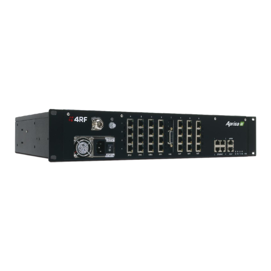
Page 17: About The Terminal
About the terminal | 15 ABOUT THE TERMINAL Introduction Aprisa radios operate in a number of frequency bands from 300 MHz up to 2.7 GHz carrying Internet, voice and data traffic over long distances up to 100 kilometers. They are designed to meet the demands of a wide range of low to medium capacity access and backhaul applications. - Page 18 16 | About the terminal Radio block diagram...
-
Page 19: Front Panel Connections And Indicators
About the terminal | 17 Front panel connections and indicators All connections to the radio are made on the front panel of the unit. A description of each front panel item is shown in the table below. Label Description AC/DC power Two types of power supply are available. -
Page 20: Interface Cards
18 | About the terminal Interface cards Each radio has eight interface slots labeled A to H. Each slot can be fitted with any interface card. Typically, the radio is delivered pre-configured with the interface cards you requested. The following interface card types are available: Name Interface Card Type Function... -
Page 21: Mounting And Installing The Hardware
4RF does not assume any liability for failure to comply with these precautions. -
Page 22: Installing The Antenna And Feeder Cable
20 | Mounting and installing the hardware Installing the antenna and feeder cable Carefully mount the antenna following the antenna manufacturer's instructions. Run feeder cable from the antenna to the terminal mounting location. Lightning protection must be incorporated into the antenna system. For more information, please contact Customer Support. -
Page 23: Alarm Termination
Mounting and installing the hardware | 21 Alarm termination Two alarm inputs and 4 outputs are provided on the RJ-45 alarm connector on the front panel. These enable an internal alarm to provide an external alarm to the network operator's existing network management system via contact closure or opening, or for an external alarm to be input into a radio and presented at the remote end as an output. -
Page 24: Dc Power
22 | Mounting and installing the hardware DC power DC power is terminated on the front panel of the radio. Two high-current contacts are used for the DC power input. A power cable with pre-terminated lugs is included in the accessory kit. The range of DC voltages is: Power Recommended... -
Page 25: Ac Power
Mounting and installing the hardware | 23 AC power The auto-sensing AC power supply is terminated on the front panel of the radio using a standard IEC plug. A power cable is included in the accessory kit, and is pre-fitted with an IEC socket connector and the country-specific plug that was specified when the order was placed. -
Page 26: Configuring A Slot
24 | Mounting and installing the hardware For more information about protected terminals, refer to Protected terminals on page 87. Configuring a slot From either the Link, Local, or Remote menus, select Interface > Slot Summary. Select the required slot and click . -
Page 27: Preparing The Terminal For New Cards
Mounting and installing the hardware | 25 Once you have configured the slot, you can install the interface card. See Installing Quad JET, 4-Wire E&M, V24 and 2-Wire interface cards on page 26 and Installing HSS interface cards on page 28. Tip: Watch for the QUICK LINKS box to appear at the bottom of page, which provides links to other related pages. - Page 28 26 | Mounting and installing the hardware Remove the securing screw from the desired interface slot, and remove the front-panel blank from the same slot. Note: Remove the blanking panel by folding the desired tab to and fro until it breaks off.
-
Page 29: Installing Quad Jet, 4-Wire E&M, V24 And 2-Wire Interface Cards
Mounting and installing the hardware | 27 Installing Quad JET, 4-Wire E&M, V24 and 2-Wire interface cards Remove the interface card from its packaging and static-safe bag. Note: To avoid static damage to the terminal or the interface card being installed, use a static discharge wristband or similar device. - Page 30 28 | Mounting and installing the hardware Re-install the securing screw removed in the previous procedure. Note: Some cards may not have the bracket to accept the retaining screw fitted. Replace the fascia and top covers, restore all cables, and power up the terminal.
-
Page 31: Installing Hss Interface Cards
Mounting and installing the hardware | 29 Installing HSS interface cards Remove the interface card from its packaging and static-safe bag. Note: To avoid static damage to the terminal or the interface card being installed, use a static discharge wristband or similar device. Install the rear mounting plate to the HSS card using one of the upper screw-locks supplied. - Page 32 30 | Mounting and installing the hardware Install the countersunk grounding screw to attach the HSS card to the chassis. Remove the screw-lock installed in step 2. Install the front mounting plate onto the HSS card, and fit the two screw-locks. Tighten firmly.
-
Page 33: Bench Setup
Mounting and installing the hardware | 31 Replace the fascia and top covers, restore all cables and power up the terminal. Bench setup Before installing the link in the field, it is recommended that you bench-test the link. A suggested setup for basic bench testing is shown below: When setting up the equipment for bench testing, note the following: Earthing—the terminals should be earthed at all times. -
Page 34: Connecting To The Terminal
32 | Connecting to the terminal CONNECTING TO THE TERMINAL About SuperVisor The embedded SuperVisor management software is an easy-to-use application, pre-loaded into an integrated web-server within the radio. SuperVisor uses SNMP and runs on any Java- enabled web browser. You can use SuperVisor to: display and configure terminal parameters monitor the performance and alarm status of the link... -
Page 35: Management Ethernet Connection And Capacity
Connecting to the terminal | 33 Management Ethernet connection and capacity The Management Ethernet capacity on each radio must be identical for remote communications to work and there should only be one IP connection to the management network. In the example above, the active management PC must only have one connection to the link as shown by path ". - Page 36 34 | Connecting to the terminal The distinction is important as: Some functions can only be carried out at the local terminal. Having different configurations at each end of the link will disrupt communications between the terminals. In these circumstances it is important to make changes to the Far end of the link first.
-
Page 37: Logging In
Connecting to the terminal | 35 Logging in Before you can view or modify any of the radio parameters, you must log in. Important: When you log in for the very first time, it is recommended that you change the admin password for security reasons. -
Page 38: Changing The Terminals' Default Ip Address
36 | Connecting to the terminal Opens the terminal detail screen for both terminals in a link. Link Opens the terminal detail screen for the local terminal in a link. Local Opens the terminal detail screen for the remote terminal in a link. Remote Provides details about the terminal. -
Page 39: Setting Up Users
Connecting to the terminal | 37 Setting up users There are three pre-defined users set up in SuperVisor: Group Default user Default Access rights name password View view view You can only view radio parameters Modify modify modify You can view and edit radio parameters Admin admin... -
Page 40: Adding A User
38 | Connecting to the terminal Adding a user Note: The User Admin menu is only visible when you are logged in with Administrator privileges. Select Select Local or Remote > Maintenance > User Admin > User Table. Select an empty line (that isn't allocated to an existing user) and then click Enter the person's name and a suitable password (up to 32 characters). -
Page 41: Deleting A User
Connecting to the terminal | 39 Deleting a user Note: The User Admin menu is only visible when you are logged in with Administrator privileges. Select Select Local or Remote > Maintenance > User Admin > User Table. Select the User who you want to delete. Click to display the User details and delete the User Name and Password. -
Page 42: Configuring The Radio
40 | Configuring the radio CONFIGURING THE RADIO Configuring the RF settings Before the link can be established, you will need to configure the RF settings for each terminal in the link. This is usually performed in the factory before dispatch. This procedure allows you to restore or change those settings, if required. -
Page 43: Configuring The Ip Settings
Configuring the radio | 41 Click to apply changes or to restore the previous configuration. You can now configure the IP address settings. Configuring the IP settings Select Radio Settings > Advanced Settings to display: Select either DHCP or Static IP addressing. If you select Static IP, you must also: Enter the IP Address for the terminal assigned by your site network administrator. -
Page 44: Setting The Clock Sources
42 | Configuring the radio Setting the clock sources Select Radio Settings > Clocking to display: Set the Clock Source to either: Network (traffic interface timing is generated from one of the Quad JET or HSS customer traffic ports), or Link (traffic interface timing is recovered from the remote end of the RF link), or Internal (traffic interface timing is generated from the terminal's internal clock). - Page 45 Configuring the radio | 43 Note: You can select which traffic interface ports are nominated as Primary or Secondary Clock sources in the configuration screen for the relevant interface ports. Refer to Configuring the traffic interface on page 43. The failure of both Network Clock sources results in a major alarm.
-
Page 46: Configuring The Traffic Interface
44 | Configuring the traffic interface CONFIGURING THE TRAFFIC INTERFACE Important: Release 5.0 software supports the Quad E1/T1, Quad 4-wire E&M, Dual FXS, Dual FXO, Quad V24 and HSS interface cards, along with the integrated Ethernet capacity. When configuring a link it is important that you configure the remote end first as this will break the link. Once the remote end has been configured the local end should be configured to match the remote end. -
Page 47: Understanding The Cross Connections Window
Configuring the traffic interface | 45 Understanding the Cross Connections window Open the Cross Connections application by starting it from either: Supervisor by selecting Link > Interface > Cross Connections, or your PC (from the Start menu, or using a desktop shortcut, for example). (This option is useful if you want to work offline.) The Cross Connections main window appears: The main page is split into two panes displaying the card complement and assigned data... - Page 48 46 | Configuring the traffic interface This shows: the current Ethernet assigned capacity in kbps the current Management capacity in kbps. The management capacity must be a multiple of 8 kbps. A minimum of 8 kbps must always be assigned for management. 64 kbps is recommended per hop.
- Page 49 Configuring the traffic interface | 47 Right-clicking the top line of the screen allows you to: Set Address Useful if you accidentally type an incorrect address when starting the application. Set Bandwidth Allows you to set the total link capacity. This is useful when creating configurations.
-
Page 50: Creating New Cross Connects
48 | Configuring the traffic interface Creating new cross connects Cross connections between any compatible interfaces of equal data rates are made by dragging and dropping between the points that require connecting. Compatible interfaces are shown in the table below: In the framed E1 interface screens each timeslot is represented by 8 squares (each representing a single bit). -
Page 51: Example 1
Configuring the traffic interface | 49 Click and drag this bit to the square representing the timeslot/bit on the interface you want it to be connected to and release the mouse button. The red squares will be replaced by the allocated connection number at each interface. -
Page 52: Example 2
50 | Configuring the traffic interface Example 2 In this more complex example, multiple voice and framed E1 connections are made over the link and between interfaces at each end of the link. Drop and insert functions have been used to take some timeslots from both the local E1 port 1 and the remote E1 Port 1 to create a new E1 bearer on the local terminal port 2. - Page 53 Configuring the traffic interface | 51...
- Page 54 52 | Configuring the traffic interface The details of the cross connect are shown below: Circuit Ports connected Capacity Connection (kbps) number Radio Local Remote management User Ethernet Local Remote Framed E1 - Local E1 Slot H port 1 Local 4W Slot G port 1 Voice TS0 bits 3,4 voice...
-
Page 55: About The Quad Jet Card Modes
Configuring the traffic interface | 53 Traffic dispersement (grooming) About the Quad JET card modes The Quad JET card can operate in several different modes allowing you greater flexibility in tailoring or grooming traffic. In the Unframed mode, you can choose between Off, E1, or T1 rates. -
Page 56: Selecting A Single Bit
54 | Configuring the traffic interface For all PCM modes timeslot 0 is transported transparently across the link. Selecting a single bit In these screens each timeslot is represented by 8 squares (each representing a single bit). Each bit can carry 8 kbps. One or more consecutive bits can be selected in a timeslot if a rate of greater than 8 kbps is required. -
Page 57: Selecting A 64 Kbps Timeslot
Configuring the traffic interface | 55 Selecting a 64 kbps timeslot A complete 64 kbps timeslot can be selected by clicking on the TSX rectangle, where X is the desired timeslot from 1 to 31. Drag and drop in the normal way to complete the cross connection. -
Page 58: Pcm31C Mode
Please contact 4RF for assistance, if required. For interworking with a third party multiplexer the same PCM/ADPCM mode must be selected in the 4-Wire card as in the multiplexer. - Page 59 Configuring the traffic interface | 57 connected to the 'A' bit for the corresponding timeslot. An example of one 4-Wire E&M channel is shown on the next page. Another use of the ABCD bits in PCM30C mode is for carrying the signalling of a 2-Wire circuit. In the example shown below, the FXS signalling from port 1 of slot A is carried in 'non- multiplexed' mode and as such requires 8 kbps of capacity;...
-
Page 60: Viewing A Summary Of The Interfaces
58 | Configuring the traffic interface Viewing a summary of the interfaces To view a summary of the interfaces fitted, select Local > Interface > Interface Summary. A window similar to this one is displayed (what you see depends on what interface cards are fitted): The Interface Summary screen shows: the interface type for each slot that has been configured. -
Page 61: Configuring The Traffic Interfaces-Overview
Configuring the traffic interface | 59 Configuring the traffic interfaces—overview Note: The management Ethernet capacity on each radio must be identical for remote communications to work. Configuring each traffic interface involves the following steps: Step 1: Specify the port settings for the remote terminal Select Remote >... -
Page 62: Initializing The Cross Connection Application
60 | Configuring the traffic interface Initializing the Cross Connection application The terminal card complement and any existing cross connects can be either: loaded from terminals, or created offline (that is, no terminals at all) to allow planning or training, or loaded from a configuration file on the PC running the application. - Page 63 Configuring the traffic interface | 61 Update the local terminal card complement in the same way by selecting Radio > Local > Discover Interfaces, and entering the IP address of the local terminal when prompted. Retrieve the existing cross connections (if any) by selecting Radio > Download From Terminal.
Need help?
Do you have a question about the Aprisa XE and is the answer not in the manual?
Questions and answers