Sign In
Upload
Manuals
Brands
Aerotech Manuals
Controller
Ensemble QLAB
Aerotech Ensemble QLAB Manuals
Manuals and User Guides for Aerotech Ensemble QLAB. We have
1
Aerotech Ensemble QLAB manual available for free PDF download: Hardware Manual
Aerotech Ensemble QLAB Hardware Manual (52 pages)
Brand:
Aerotech
| Category:
Controller
| Size: 3 MB
Table of Contents
Technical Support
2
Table of Contents
3
List of Figures
4
List of Tables
5
EC Declaration of Conformity
7
Safety Procedures and Warnings
9
Quick Installation Guide
11
Chapter 1: Introduction
13
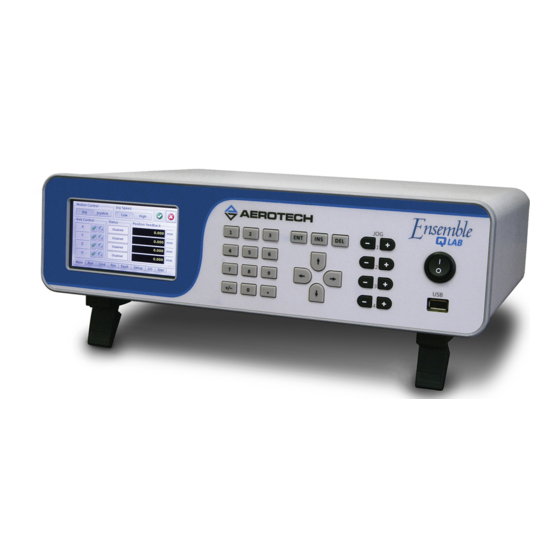
Figure 1-1: Ensemble QLAB Controller
13
Table 1-1: Ordering Options
14
Figure 1-2: Functional Diagram
15
Electrical Specifications
16
Table 1-2: Electrical Specifications
16
Figure 1-3: Dimensions
17
Mechanical Specifications
17
Table 1-3: Physical Specifications
17
Environmental Specifications
18
Drive and Software Compatibility
19
Table 1-4: Ensemble Drive and Software Compatibility
19
Chapter 2: Installation and Configuration
21
Unpacking the Chassis
21
Electrical Installation
22
Figure 2-1: Power and Control Connections
22
Figure 2-2: Power Switch
22
AC Power Connection
23
IO and Signal Wiring Requirements
23
Table 2-1: Main AC Power Input Voltages and Current Requirements
23
Minimizing Conducted, Radiated, and System Noise
24
Table 2-2: Ferrite Bead Part Numbers
24
Motor and Feedback Connections
25
Table 2-3: Motor Power and Feedback Connector
25
Emergency Stop Sense Input (TB101)
26
Figure 2-3: ESTOP Sense Input (TB102)
26
Table 2-4: TB101 ESTOP Pin Assignment
26
Table 2-5: Electrical Noise Suppression Devices
26
Auxiliary I/O Connector (J106)
27
Table 2-6: Auxiliary I/O Interface Pin Assignment (J106)
27
Table 2-7: Auxiliary I/O (J106) Mating Connector
27
Position Synchronized Output (PSO)
28
Table 2-8: PSO Output Pin Assignment
28
Figure 2-4: PSO Interface
29
Figure 2-5: Outputs Connected in Current Sinking Mode (J106)
30
Opto-Isolated Outputs
30
Table 2-10: Digital Output Specifications
30
Table 2-9: Port 0 Digital Output Connector Pin Assignment
30
Figure 2-6: Outputs Connected in Current Sourcing Mode (J106)
31
Figure 2-7: Inputs Connected in Current Sinking Mode (J106)
32
Opto-Isolated Inputs
32
Table 2-11: Port 0 Digital Input Connector Pin Assignment (J106)
32
Table 2-12: PS2815-4 Opto-Device Specifications
32
Figure 2-8: Inputs Connected in Current Sourcing Mode (J106)
33
Figure 2-9: High Speed User Inputs (J106)
34
High-Speed User Inputs
34
Table 2-13: Port 0 High Speed Digital Input Connector Pin Assignment (J106)
34
Analog Output
35
Figure 2-10: Analog Output 4 (J106)
35
Table 2-14: Analog Output Connector Pin Assignment (J106)
35
Joystick Interface (J105)
36
Figure 2-11: Joystick Interface
36
Table 2-15: Joystick Connector Pin Assignment (J105)
37
Table 2-16: Joystick Interface (J105) Mating Connector
37
Analog Outputs (0-3) (J105)
38
Figure 2-12: Analog Outputs 0-3 (J105)
38
Table 2-17: Analog Output Connector Pin Assignment (J105)
38
Analog Inputs (0-3) (J105)
39
Figure 2-13: Analog Input (J105)
39
Table 2-18: Analog Input Connector Pin Assignment (J105)
39
Communication (Ethernet and USB)
40
USB Interface
40
Figure 2-14: USB Connection Location (for PC Communication)
40
Ethernet Interface
41
Figure 2-15: Ethernet Connection Location
41
PC Configuration and Operation Information
42
Chapter 3: Maintenance
43
Preventative Maintenance
43
Table 3-1: Preventative Maintenance
43
Appendix A: Warranty and Field Service
45
Appendix B: Revision History
47
Index
49
Advertisement
Advertisement
Related Products
Aerotech Ensemble HLe
Aerotech Ensemble QLe Series
Aerotech Ensemble QL
Aerotech Ensemble Epaq
Aerotech Ensemble CP Series
Aerotech Ensemble LAB
Aerotech Ensemble CL
Aerotech Ensemble CP 20
Aerotech Ensemble CP 30
Aerotech ENSEMBLECP10
Aerotech Categories
Industrial Equipment
DC Drives
Controller
Engine
Amplifier
More Aerotech Manuals
Login
Sign In
OR
Sign in with Facebook
Sign in with Google
Upload manual
Upload from disk
Upload from URL