Table of Contents
Advertisement
Quick Links
Advertisement
Table of Contents

Related Manuals for ETS-Lindgren 3127 Series


Summary of Contents for ETS-Lindgren 3127 Series
- Page 1 Model 3127 Resonant Loop Antenna User Manual...
- Page 2 ETS-Lindgren Inc. reserves the right to make changes to any product described herein in order to improve function, design, or for any other reason. Nothing contained herein shall constitute ETS-Lindgren Inc. assuming any liability whatsoever arising out of the application or use of any product or circuit described herein.
-
Page 3: Table Of Contents
Table of Contents Notes, Cautions, and Warnings ..........v General Safety Considerations ..........v 1.0 Introduction ................7 Standard Configuration ................8 ETS-Lindgren Product Information Bulletin ..........8 2.0 Maintenance ................. 9 Maintenance Recommendations ..............9 Annual Calibration ..................9 Replacement and Optional Parts .............. - Page 4 This page intentionally left blank. www.ets-lindgren.com...
-
Page 5: Notes, Cautions, And Warnings
Notes, Cautions, and Warnings Note: Denotes helpful information intended to provide tips for better use of the product. Caution: Denotes a hazard. Failure to follow instructions could result in minor personal injury and/or property damage. Included text gives proper procedures. Warning: Denotes a hazard. - Page 6 This page intentionally left blank. www.ets-lindgren.com...
-
Page 7: Introduction
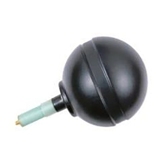
1.0 Introduction ETS-Lindgren Model 3127 Resonant Loop Antennas are magnetic dipole antennas designed to meet the Cellular Telecommunication and Internet Association’s (CTIA)) +/- 0.1 dB symmetry requirement for ripple test measurements at the labeled center frequency. These omni-directional antennas have a magnetic dipole pattern approaching that of a half wave resonant electric dipole. -
Page 8: Standard Configuration
The Model 3127 antenna family covers a range of frequencies intended for characterization of wireless chambers including, but not limited to, the following models: 3127-450 3127-1800 3127-700 3127-1868 3127-836 3127-1880 3127-880 3127-1950 3127-897 3127-2140 3127-920 3127-2450 3127-1747 3127-2535 3127-1768 3127-2655 3127-5500 The digits following the hyphen in the model name note the center frequency of the antenna. -
Page 9: Maintenance
2.0 Maintenance Before performing any maintenance, follow the safety information in the ETS-Lindgren Product Information Bulletin included with your shipment. Maintenance of the loop antenna is limited WARRANTY to external components such as cables or connectors. If you have any questions concerning maintenance, contact ETS-Lindgren Customer Service. -
Page 10: Upgrade Policies
Upgrade Policies Periodically, Field Probes are upgraded to enhance functionality. Contact ETS-Lindgren Customer Service for the upgrade status of your Field Probe. Service Procedures For the steps to return a system or system component to ETS-Lindgren for service, see the Product Information Bulletin included with your shipment. Maintenance www.ets-lindgren.com... -
Page 11: Specifications
3.0 Specifications Electrical Specifications VSWR Ratio (Average) <5:1 Typical Max. Continuous Power 1 Watt Impedance (Nominal) 50 Ohms Connector The symmetry is guaranteed over a 10MHz span less than 1880 MHz, above that frequency the symmetry is only guaranteed at the nominal frequency. -
Page 12: Physical Specifications 3127-5500 Only
Physical Specifications 3127-5500 Only Diameter A: 1.9 cm (0.75 in) Diameter B: 6.4 cm (2.5 in) Length: 18.7 cm (7.38 in) Specifications www.ets-lindgren.com... -
Page 13: Operation
4.0 Operation Before operating any components, follow the safety information in the ETS-Lindgren Product Information Bulletin included with your shipment. Mounting All items mentioned in the Mounting section are options. Please contact ETS-Lindgren Customer Service for additional information. The Model 3127 Resonant Loop Antennas should be mounted to a support at the connector end of the antenna. -
Page 14: Operational Considerations
Ferrite loaded RF cables are recommended for use with the Model 3127 to minimize the interaction with the loop. ETS-Lindgren offers a line of ferrite loaded cables for this application. Lightweight RF cabling should be used and properly supported to avoid putting unnecessary load on the SMA connector of the antenna. -
Page 15: Appendix A: Warranty
Appendix A: Warranty See the Product Information Bulletin included with your shipment for the complete ETS-Lindgren warranty for your Model 3127. 3127 URATION OF ARRANTIES FOR ODEL All product warranties, except the warranty of title, and all remedies for warranty failures are limited to two years.
Need help?
Do you have a question about the 3127 Series and is the answer not in the manual?
Questions and answers