Table of Contents
Advertisement
Quick Links
Advertisement
Table of Contents

Related Manuals for Advantech DSPC-8661-PCXE


Summary of Contents for Advantech DSPC-8661-PCXE
- Page 1 User Manual DSPC-8661-PCXE...
- Page 2 No part of this manual may be reproduced, copied, translated or transmitted in any form or by any means without the prior written permission of Advantech Co., Ltd. Information provided in this manual is intended to be accurate and reliable. How- ever, Advantech Co., Ltd.
-
Page 3: Declaration Of Conformity
This product has passed the CE test for environmental specifications when shielded cables are used for external wiring. We recommend the use of shielded cables. This kind of cable is available from Advantech. Please contact your local supplier for ordering information. -
Page 4: Safety Instructions
Technical Support and Assistance Visit the Advantech web site at www.advantech.com/support where you can find the latest information about the product. Contact your distributor, sales representative, or Advantech's customer service center for technical support if you need additional assistance. Please have the following information ready before you call: –... - Page 5 The sound pressure level at the operator's position according to IEC 704-1:1982 is no more than 70 dB (A). DISCLAIMER: This set of instructions is given according to IEC 704-1. Advantech disclaims all responsibility for the accuracy of any statements contained herein.
- Page 6 DSPC-8661-PCXE User Manual...
-
Page 7: Table Of Contents
Figure 1.2 Typical Application............4 HW Introduction ..................5 1.7.1 Dimension ..................5 Figure 1.3 Top View of DSPC-8661-PCXE ......... 5 Figure 1.4 Bottom View of DSPC-8661-PCXE ......6 Figure 1.5 Side View of DSPC-8661-PCXE ........ 6 1.7.2 Input / Output Ports............... 7 Optional Accessories ................ - Page 8 DSPC-8661-PCXE User Manual viii...
-
Page 9: Chapter 1 Introduction
Chapter Introduction... -
Page 10: Introduction
Introduction Design with TI TMS320DM8168 SoC, DSPC-8661-PCXE is a full-functional video processing platform with 16-ch composite video and audio inputs based on standard half-length PCIe board form factor. The board supports H.264 / MJPEG / RAW encode / decode up to D1 resolution at real-time frame rate (30/25fps) for all chan- nels simultaneously. - Page 11 PCIe Device Mode PCIe video decoder card with HDMI out PCIe DSP-based intelligent video analytic card Embedded IP video encoder / video recorder Standalone Mode Embedded IP video decoder with HDMI out Embedded IP intelligent video analytic box DSPC-8661-PCXE User Manual...
-
Page 12: Block Diagram
Camera x16 Encode DSPC-8661-PCXE X86 PC Storage -Windows OS - Linux OS Network Standalone Mode Image Processing Decode Video Analy cs Display Analog Camera x16 Camera x16 DSPC-8661-PCXE Encode Storage - Linux OS Figure 1.2 Typical Application DSPC-8661-PCXE User Manual... -
Page 13: Hw Introduction
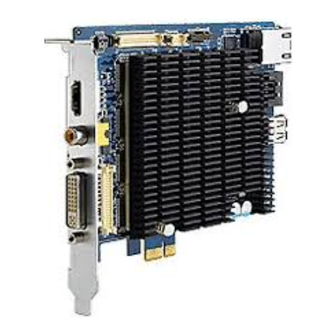
HW Introduction 1.7.1 Dimension Figure 1.3 Top View of DSPC-8661-PCXE DSPC-8661-PCXE User Manual... -
Page 14: Figure 1.4 Bottom View Of Dspc-8661-Pcxe
Figure 1.4 Bottom View of DSPC-8661-PCXE Figure 1.5 Side View of DSPC-8661-PCXE DSPC-8661-PCXE User Manual... -
Page 15: Input / Output Ports
(Audio-in ch1~ch8) 1.7.2.1 Boot Mode Switch DSPC-8661-PCXE supports dual working modes: PCIe device mode and Standalone mode. The Boot Mode Switch is for switching the two boot modes. PCIe boot (PCIe device mode): 1:OFF , 2:ON, 3:OFF , 4:ON (default) - Page 16 The DVI port connects with the octopus cable for providing 16ch Video + 8ch Audio inputs (ch1~ch8). Pin number Pin signal Pin number Pin signal VIDEO_IN1 VIDEO_IN13 VIDEO_IN2 VIDEO_IN14 VIDEO_IN3 VIDEO_IN15 VIDEO_IN4 VIDEO_IN16 VIDEO_IN5 AUDIO_IN1 VIDEO_IN6 AUDIO_IN2 VIDEO_IN7 AUDIO_IN3 VIDEO_IN8 AUDIO_IN4 VIDEO_IN9 AUDIO_IN5 VIDEO_IN10 AUDIO_IN6 VIDEO_IN11 AUDIO_IN7 VIDEO_IN12 AUDIO_IN8 DSPC-8661-PCXE User Manual...
- Page 17 The DIO & control port connects with the DIO & control board (optional) through I2C and UART for providing: 16x DI + 8x DO RS485 Pin number Pin signal Pin number Pin signal UART1_TXD VCC_5V UART1_RXD VCC_5V RS485_DIR IIC1_SCL VCC_3V3 IIC1_SDA 9555_INTn DSPC-8661-PCXE User Manual...
- Page 18 Pin number Pin signal VCC_3V3 VCC_1V8 V_loop_1 AUDIO_IN9 V_loop_2 AUDIO_IN10 V_loop_3 AUDIO_IN11 V_loop_4 AUDIO_IN12 V_loop_5 AUDIO_IN13 V_loop_6 AUDIO_IN14 V_loop_7 AUDIO_IN15 V_loop_8 AUDIO_IN16 V_loop_9 V_loop_13 V_loop_10 V_loop_14 V_loop_11 V_loop_15 V_loop_12 V_loop_16 AU_3101_DIN RSTOUTn AU_3101_DOUT AU_3101_MCLK IIC0_SCL AU_3101_BCLK IIC0_SDA AU_3101_WCLK DSPC-8661-PCXE User Manual...
- Page 19 RCA connectors on the brackets directly. Pin number Pin signal Pin number Pin signal VIDEO_IN5 AUDIO_IN1 VIDEO_IN6 AUDIO_IN2 VIDEO_IN7 AUDIO_IN3 VIDEO_IN8 AUDIO_IN4 VIDEO_IN9 AUDIO_IN5 VIDEO_IN10 AUDIO_IN6 VIDEO_IN11 AUDIO_IN7 VIDEO_IN12 AUDIO_IN8 VIDEO_IN13 VIDEO_IN14 VIDEO_IN1 VIDEO_IN2 VIDEO_IN15 VIDEO_IN16 VIDEO_IN3 VIDEO_IN4 DSPC-8661-PCXE User Manual...
- Page 20 MDI3_N Left LED Orange Color LED Right LED Green Color LED 1.7.2.8 SATA II Port The SATA II Port is a standard SATA connector for providing data storage functions Pin number Pin signal CON.SATA_TXP0 CON.SATA_TXN0 CON.SATA_RXN0 CON.SATA_RXP0 DSPC-8661-PCXE User Manual...
- Page 21 Pin number Pin signal HDMI_TMDSDP2 HDMI_TMDSCLKN HDMI_TMDSDN2 HDMI0_CEC_C HDMI_TMDSDP1 HDMI0_DCLK_C HDMI_TMDSDN1 HDMI0_DSDA_C HDMI_TMDSDP0 HDMI0_CN_5V HDMI_TMDSDN0 HDMI0_HPD_C HDMI_TMDSCLKP 1.7.2.11 The RCA connector is for connecting with monitor / display devices for provide stan- dard definition video output functions. DSPC-8661-PCXE User Manual...
-
Page 22: Optional Accessories
Optional Accessories 1.8.1 JTAG Debug Board (optional) The JTAG debug board (P/N: DSPC8661ACY001-E) is an optional accessory of DSPC-8661-PCXE for monitoring the board operating status and FW/SW program- ming. A board-to-board flat cable is attached. 1.8.2 Audio and Loop-out Board (optional) -
Page 23: Dio And Control Board (Optional)
Video_Loop12 Video_Loop13 Video_Loop14 Video_Loop15 1.8.3 DIO and Control Board (optional) The DIO and Control Board (P/N: DSPC8661ACY003-E) is an optional accessory of DSPC-8661-PCXE for providing: 16x digital input 8x digital output (relay) RS485 A board-to-board flat cable is attached. - Page 24 3 COM Alarm in 07 3 NO Alarm in 08 2 COM Alarm in 05 2 NO Alarm in 06 1 COM Alarm in 03 1 NO Alarm in 04 +485 Alarm in 01 -485 Alarm in 02 DSPC-8661-PCXE User Manual...
-
Page 25: Chapter 2 Linux Demo Program
Chapter Linux Demo Program... -
Page 26: Introduction
Connect to input source you want. Connect with JTAG debug board for UART message and JTAG function (optional). COM port cable (or USB-to-COM cable, optional). Insert DSPC-8661 into your PC PCIE slot and ready for boot, as shown in below. DSPC-8661-PCXE User Manual... -
Page 27: Boot From Customized Ubuntu Disc
Please download the “DSPC-8661-PCXE Linux SDK + Live Linux Demo” data from Advantech “Support & Download” web page and save in the hard disk. Setting PC to boot from this bootable device with ISO image and chose “Try Ubuntu without install- ing”... -
Page 28: Run Demonstration
Set “all” to capture all channels and ‘0-15’ for individually channel. Frame rate depends on the format of the video source: 25 for PAL, 30 for NTSC. And set encode format: 0= H264; 1=RAW ;2=MJPEG ; 9=previous setting. DSPC-8661-PCXE User Manual... - Page 29 After arguments setting the terminal will show decoding error message until PCIe on- board firmware is running, as shown in below. Multiple Mplayer windows will pop-out. DSPC-8661-PCXE User Manual...
- Page 30 DSPC-8661-PCXE User Manual...
-
Page 31: Chapter 3 Windows Driver Installation
Chapter Windows Driver Installation For Windows XP For Windows Vista For Windows 7... -
Page 32: For Windows Xp
If it doesn’t show, or you want to reinstall the driver, please re-scan hardware for DSPC-8661. If “Found New Hardware Wizard” shows, click on “Cancel” to prevent it from blocking the driver installer. Make sure the wizard is closed, or the installation process fails. DSPC-8661-PCXE User Manual... - Page 33 Double click on “Install.bat” to begin the installation. Click “Next” when the installation wizard shows. DSPC-8661-PCXE User Manual...
- Page 34 Choose “Agree” and click “Next” on EULA step. The driver wizard proceeds to install. DSPC-8661-PCXE User Manual...
-
Page 35: For Windows Vista
Device Found: After DSPC-8661 is plugged into your PC, Windows scans the hardware and finds out DSPC-8661. Open your “Device Manager” and it show as the following figure. If it doesn’t show, or you want to reinstall the driver, please re-scan hardware for DSPC-8661. DSPC-8661-PCXE User Manual... - Page 36 If “Found New Hardware Wizard” shows, click on “Cancel” to prevent it from blocking the driver installer. Make sure the wizard is closed, or the installation process fails. Double click on “Install.bat” to begin the installation. DSPC-8661-PCXE User Manual...
- Page 37 Click “Next” when the installation wizard shows. Choose “Agree” and click “Next” on EULA step. DSPC-8661-PCXE User Manual...
- Page 38 The will show windows Security message, click “Install”. The driver wizard pro- ceeds to install. DSPC-8661-PCXE User Manual...
-
Page 39: For Windows 7
Device Found: After DSPC-8661 is plugged into your PC, Windows scans the hardware and finds out DSPC-8661. Open your “Device Manager” and it show as the following figure. If it doesn’t show, or you want to reinstall the driver, please re-scan hardware for DSPC-8661. DSPC-8661-PCXE User Manual... - Page 40 Double click on “Install.bat” to begin the installation. Click “Next” when the installation wizard shows. DSPC-8661-PCXE User Manual...
- Page 41 Choose “Agree” and click “Next” on EULA step. DSPC-8661-PCXE User Manual...
- Page 42 The will show windows Security message, click “Install”. The driver wizard pro- ceeds to install. DSPC-8661-PCXE User Manual...
- Page 43 When the installation successfully completed, click “Finish” to end the installation. DSPC-8661-PCXE User Manual...
- Page 44 DSPC-8661-PCXE User Manual...
-
Page 45: Chapter 4 Firmware Loader For Windows
Chapter Firmware Loader for Windows... - Page 46 Linux EZ Software Development Kit (EZSDK) for DaVinci DM816X Video Processors in the Texas Instruments (TI) website. “Dspc8661loader” looks like as following: Display which board to load. Display the firmware path. The following is the loading flow: DSPC-8661-PCXE User Manual...
- Page 47 _x862008sp1.exe” is located in the folder “DSPC-8661 Loader\application”. If the driver and the Microsoft application are successfully installed, please refer to the following steps to start to use the application “Dspc8661Loader”. Find the application “Dspc8661Loader” in “DSPC-8661 Loader\application” Run “Dspc8661Loader” as administrator. DSPC-8661-PCXE User Manual...
- Page 48 Find all the firmware to load. A. Find the firmware *.bin to load. B. Find the firmware *.scr to load DSPC-8661-PCXE User Manual...
- Page 49 C. Find the firmware *.ker to load. D. Find the firmware *.fs to load Start to load all the firmware by pressing the button “Load”. DSPC-8661-PCXE User Manual...
- Page 50 Wait for about 30 seconds, then message “Load finish” pop up once the loading already finished. DSPC-8661-PCXE User Manual...
- Page 51 DSPC-8661-PCXE User Manual...
- Page 52 No part of this publication may be reproduced in any form or by any means, electronic, photocopying, recording or otherwise, without prior written permis- sion of the publisher. All brand and product names are trademarks or registered trademarks of their respective companies. © Advantech Co., Ltd. 2014...
Need help?
Do you have a question about the DSPC-8661-PCXE and is the answer not in the manual?
Questions and answers