Table of Contents
Advertisement
Advertisement
Table of Contents

Related Manuals for Erbauer ERB380ROU


Summary of Contents for Erbauer ERB380ROU
- Page 1 ERB380ROU 2100w ROUTER...
- Page 2 Original Instructions (Version 1.0)
- Page 3 Congratulations on your purchase of a quality power tool from Erbauer (UK) Ltd. This product should give you reliable service but for your peace of mind this power tool does carry a 2 year guarantee, the terms of which are detailed below.
- Page 4 GENERAL SAFETY INSTRUCTIONS WARNING! Read all safety warnings and all instructions. Failure to follow the warnings and instructions may result in electric shock, fire and/or serious injury. Save all warnings and instructions for future reference. The term “power tool” in the warnings refers to your mains-operated (corded) power tool or battery-operated (cordless) power tool.
- Page 5 f. Dress properly. Do not wear loose clothing or jewellery. Keep your hair, clothing and gloves away from moving parts. Loose clothes, jewellery or long hair can be caught in moving parts. g. If devices are provided for the connection of dust extraction and collection facilities, ensure these are connected and properly used.
- Page 6 ADDITIONAL SAFETY INSTRUCTIONS FOR YOUR ROUTER 1. Hold tool by insulated gripping surfaces when performing an operation where the cutting tool may contact hidden wiring. Contact with a “live” wire will make exposed metal parts of the tool “live” and shock the operator. 2.
- Page 7 VIBRATION The European Physical Agents (Vibration) Directive has been brought in to help reduce hand arm vibration syndrome injuries to power tool users. The directive requires power tool manufacturers and suppliers to provide indicative vibration test results to enable users to make informed decisions as to the period of time a power tool can be used safely on a daily basis and the choice of tool.
- Page 8 Plan your work schedule to spread any high vibration tool use across a number of days. Health Surveillance All employees should be part of an employer’s health surveillance scheme to help identity any vibration related diseases at an early stage, prevent disease progression and help employees stay in work.
- Page 9 SYMBOLS To reduce the risk of injury, user must read instruction manual Warning Double insulation Wear ear protection Wear eye protection Wear dust mask Waste electrical products should not be disposed of with household waste. Please recycle where facilities exist. Check with your Local Authority or retailer for recycling advice.
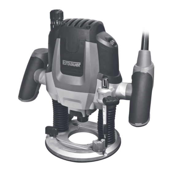
- Page 11 FINE-ADjUSTMENT KNob FoR DEPTH-oF-CUT SCALE FoR FINE ADjUSTMENT oF DEPTH-oF-CUT CLAMPING LEvER LEFT HANDLE SCALE FoR CoARSE ADjUSTMENT oF DEPTH-oF-CUT DEPTH SToP WING SCREW FoR DEPTH SToP DUST booTS STEP bUFFER bASE PLATE GUIDE PLATE LoCKING SCREW FoR GUIDE RoD CoLLET NUT SPINDLE LoCK bUTToN RIGHT HANDLE (WITH oN/oFF SWITCH)
- Page 12 TECHNICAL DATA Rated voltage 220-240V~50Hz Rated power 2100W Rated no-load speed 11500~28000/min Collet size 1/2” and 1/4” Max plunge depth 50mm Double insulation Machine weight 4.3Kg NOISE DATA Sound pressure level: : 90 dB (A) =3.0 dB (A) Sound power level: : 101 dB (A) =3.0 dB (A) Wear ear protection when sound pressure is over...
- Page 13 OPERATION INSTRUCTIONS NoTE: before using the tool, read the instruction book carefully. INTENDED USE The machine is intended for routing grooves, edges, profiles and elongated holes as well as for copy routing in wood, plastic and light building materials, while resting firmly on the workpiece. 1.
- Page 14 Tighten the collet nut (13) with the spanner (19). Release the spindle lock button. Warning: Do not tighten the collet nut (13) without a router bit inserted. HoW To FIT THE 1/4˝ CoLLET (See Fig a) Your router is supplied with a 1/2” collet fitted to the tool.
- Page 15 After longer periods of working at low speed, allow the machine to cool down by running it for approx. 3 minutes at maximum speed with no load. Speed Table Material Router bit-Ø Speed stages 4 – 10 mm 5–6 Hardwood 12 –...
- Page 16 alignment as (shown in Fig 4). Afterwards turn scale (2) to “0” (See Fig 4). Set step buffer (9) to the lowest position, the buffer snaps-in noticeably. Loosen wing screw (7), so that depth stop (6) can be moved freely. Release the clamping lever (3) by turning in clockwise direction and slowly lower the router until the router bit touches the surface of the workpiece.
- Page 17 step buffer, the cutting process can be divided into several steps. Set the required depth-of-cut with the lowest step of the step buffer. Afterwards, the higher steps can be used for the last two cuts. b) Pre-adjustment of varying depth-of-cuts If several different depth-of-cuts are required for the machining of a work-piece, these can also be preset by using the step buffer.
- Page 18 is reached. Guide router with projecting guide bush along the template, applying light sideward pressure. NoTE: The template must have a minimum thickness of 8 mm, due to the projecting height of the guide bush. 9. SHAPING oR MoULDING APPLICATIoNS For shaping or molding applications without the use of a parallel guide, the router bit must be equipped with a pilot or a ball bearing.
- Page 19 side of the router where the locking screws (12) are located. • Mark the workpiece at the centre of the desired circle. • Loosen the screw of centre pin (22), and fit into the centre hole of the adjustment guide (F), then fasten the screw to use. • Place the centre pin against the mark of desired circle on the workpiece.
- Page 20 PLUG REPLACEMENT The fuse in the main plug of your power tool should always be replaced with one of identical rating. Check the voltage given on your power tool matches the supply voltage. The power tool is supplied with a fitted plug, however if you should need to fit a new plug follows the instruction below.
- Page 21 EN 55014-1 EN 55014-2 EN 61000-3-2 EN 61000-3-3 EN 60745-1 EN 60745-2-17 Authorised Signatory and technical file holder Date: 07/04/11 Signature: Name / title: Peter Harries / Quality Manager Erbauer (UK) Ltd. Trade House, Mead Avenue, BA22 8RT 2100w ROUTER...
Need help?
Do you have a question about the ERB380ROU and is the answer not in the manual?
Questions and answers