Advertisement
Advertisement
Table of Contents

Summary of Contents for Classe Audio CP-35
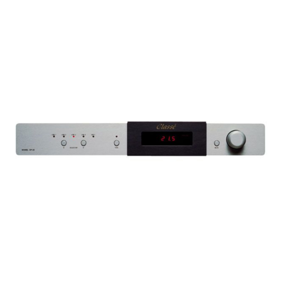
- Page 1 Classé CP-35 PREAMPLIFIER SERVICE MANUAL v 1.0...
-
Page 2: Pc Boards
Index Mechanical Assembly PC Boards Testing Procedures Diagrams... -
Page 3: Mechanical Assembly
CP-35 MECHANICAL ASSEMBLY Classé - 25... -
Page 4: Face Plate Assembly
FACE PLATE ASSEMBLY CP-35 < 1 MS-2347 PHILIPS 2 L103XR03 3 L104XR02 Classé - 1... -
Page 5: Top View
FACE PLATE ASSEMBLY CP-35 TOP VIEW SIDE VIEW 2 SIDE VIEW 1 5 L156XR01-S Classé - 2... -
Page 6: Chassis Rear View
CHASSIS REAR VIEW CP-35 Classé - 3... - Page 7 CHASSIS CP-35 TOP VIEW 1 PLA CAPFR1 2 HDW #8 FLAT WASHER 3 BZO 8-32x3/4” BHCS 4 L101XR04 Classé - 6...
- Page 8 PARTIAL ASSY CP-35 TOP VIEW 1 AVR BO51XR02 2 AVR BO50XR03 3 AVR BO1CXR00 4 TRANSFORMER Classé - 8...
- Page 9 PHONO BOARD INSTALLATION CP-35 SIDE VIEW Classé - 8...
- Page 10 SHIPPING AREA - FINAL ASSY CP-35 < 1 L102XR00 Classé - 9...
- Page 11 CP-35 PC BOARDS Classé - 25...
- Page 12 B101XR03 MAINBOARD CP-35 Classé - 10...
- Page 13 B103XR02 FRONT PCB CP-35 Classé - 11...
- Page 14 B0F9XR02 PHONO CP-35 Classé - 11...
-
Page 15: Testing Procedures
CP-35 TESTING PROCEDURES Classé - 25... - Page 16 INSPECTION Visually check all parts for: solder bridges or splashes, backwards, missing components and component orientation. Power supply voltages Apply 30 VAC & check polarities Apply 60 VAC check voltages Apply 120 VAC Q1 => 7805 CD3 => +12V CD4 => +5V Q2 =>...
- Page 17 FINAL TEST CP-35 1. Before final test unit was 4 days on burn-in-bench with music. 2. Take the unit from burn-in-bench to Q.C and play it immediately. Keep the line 120V A.C. 3. Check physically and check the components. -check all capacitor and devices direction. Capacitor stand up right way i.e. check co- solder.
-
Page 18: Diagrams
CP-35 DIAGRAMS Classé - 25... - Page 19 MAINBOARD - B101XR02 (1) CP-35 Classé - 16...
-
Page 20: Classé
MAINBOARD - B101XR02 (2) CP-35 Classé - 17... - Page 21 MAINBOARD PREAMP (LEFT) - B101XR02 (3) CP-35 Classé - 18...
- Page 22 MAINBOARD PREAMP (RIGHT) - B101XR02 (4) CP-35 Classé - 19...
- Page 23 PANEL - B103XR01 CP-35 Classé - 20...
- Page 31 CP-35 Block Diagram Single-ended Input Selector Pre-out Volume Gain Stage Control Balanced Input Balanced Balanced Input Selector Selector Input Single-end Conversion...
- Page 32 CP35 MAIN BOARD (B101XR03) 1. INSPECTION a) Visually check all parts for: solder bridges or splashes, backwards, missing components and component orientation. 2. Power supply voltages a) Apply 30 VAC & check polarities b) Apply 60 VAC check voltages c) Apply 120 VAC 1.
- Page 33 7. Q8→ 7805 C43→ +5V C41→ +12V 8. Q7→ 7912 C28→ -18V C30→ -12V 9. Q6→ 7812 C27→ +18V C29→ +12V 10. Tip 107→ Q102, Q202, Q302, Q402 a) C110, C210, C310, C40 → -18V 11. Tip 102→ Q101, Q102, Q201, Q301, Q401 a) C108, C208, C308, C408 +18V 12.
- Page 34 • Measure across capacitors: a) C103, C203, C303, C403→ 2.5V 18. Bias voltages → 150MV to 200 MV • Measure across resistors a) R108, R107, R207, R208, R308, R307, R407, R408 19. Offset→ 10MV (+) or (-) maximum measure W/Respect to GND.
- Page 35 CP-35 Display (B103XR02) 1. INSPECTION a) Visually check all parts for: solder bridges or splashes, backwards or missing parts and component orientation. b) Sockets on light bars must be 3 layers. c) C3, R1, C18 are empty. d) Check double side tape on the bottom of the socket.
- Page 36 Adjusting CP-35 Gain to Unity 1- Disconnect unit from the AC line and from the system 2- Remove the top cover 3- Locate and remove resistors R202 and R402 4- Locate and replace resistors R103 and R303 from the old value (86.6 Kohms) to the new value of 21.5 Kohms...


Need help?
Do you have a question about the CP-35 and is the answer not in the manual?
Questions and answers