
Related Manuals for Supero SUPERSERVER 6016XT-TF


Summary of Contents for Supero SUPERSERVER 6016XT-TF
- Page 1 UPER ® 6016XT-TF UPER ERVER 6016GT-TF UPER ERVER 6016GT-TF-TM2 UPER ERVER 6016GT-TF-TC2 UPER ERVER USER’S MANUAL Revision 1.0...
- Page 2 The information in this User’s Manual has been carefully reviewed and is believed to be accurate. The vendor assumes no responsibility for any inaccuracies that may be contained in this document, makes no commitment to update or to keep current the information in this manual, or to notify any person or organization of the updates.
-
Page 3: About This Manual
TF/6016GT-TF/6016GT-TF-TM2/6016GT-TF-TC2. Installation and maintenance should be performed by experienced technicians only. The SuperServer 6016XT-TF/6016GT-TF/6016GT-TF-TM2/6016GT-TF-TC2 is based on the SC818GTQ-1400B 1U rackmount server chassis and the Super X8DTG-DF serverboard. Please refer to our web site for an up-to-date list of sup- ported operating systems, processors and memory. - Page 4 UPER ERVER 6016XT-TF/6016GT-TF/TF-TM2/TF-TC2 User's Manual Chapter 5: Advanced Serverboard Setup Chapter 5 provides detailed information on the X8DTG-DF serverboard, including the locations and functions of connectors, headers and jumpers. Refer to this chap- ter when adding or removing processors or main memory and when reconfi guring the serverboard.
- Page 5 Preface Notes...
-
Page 6: Table Of Contents
UPER ERVER 6016XT-TF/6016GT-TF/TF-TM2/TF-TC2 User's Manual Table of Contents Chapter 1 Introduction Overview ......................1-1 Serverboard Features ..................1-2 Processors ...................... 1-2 Memory ......................1-2 Serial ATA ....................... 1-2 PCI Expansion Slots ..................1-2 Onboard Controllers/Ports ................1-2 IPMI ......................... 1-3 Other Features .................... - Page 7 Table of Contents Checking the Serverboard Setup ..............2-10 Checking the Drive Bay Setup ...............2-11 Chapter 3 System Interface Overview ......................3-1 Control Panel Buttons ..................3-1 Reset ....................... 3-1 Power ......................3-1 Control Panel LEDs ..................3-2 Universal Information LED ................3-2 NIC2 ........................
- Page 8 5-10 Onboard Indicators ..................5-20 5-11 SATA Ports ....................5-21 5-12 Installing Software ..................5-22 Supero Doctor III ................... 5-23 Chapter 6 Advanced Chassis Setup Static-Sensitive Devices .................. 6-1 Precautions ..................... 6-1 Control Panel ....................6-2 System Cooling ....................6-2 System Fan Failure ..................
-
Page 9: Chapter 1 Introduction
Chapter 1 Introduction Overview The SuperServer 6016XT-TF/6016GT-TF/6016GT-TF-TM2/6016GT-TF-TC2 is a GPU-optimized supercomputing server comprised of two main subsystems: the SC818GTQ-1400B 1U server chassis and the X8DTG-DF Intel® Xeon® processor 5500 series serverboard. Please refer to our web site for information on operating systems that have been certifi... -
Page 10: Serverboard Features
ERVER 6016XT-TF/6016GT-TF/TF-TM2/TF-TC2 User's Manual Serverboard Features At the heart of the SuperServer 6016XT-TF/6016GT-TF/6016GT-TF-TM2/6016GT- TF-TC2 lies the X8DTG-DF, a dual processor serverboard based on the Intel 5520 chipset. Below are the main features of the X8DTG-DF. (See Figure 1-1 for a block diagram of the chipset). -
Page 11: Ipmi
Chapter 1: Introduction IPMI IPMI (Intelligent Platform Management Interface) is a hardware-level interface speci- fi cation that provides remote access, monitoring and administration for Supermicro server platforms. IPMI allows server administrators to view a server’s hardware status remotely, receive an alarm automatically if a failure occurs, and power cycle a system that is non-responsive. -
Page 12: Gpu Subsystem
UPER ERVER 6016XT-TF/6016GT-TF/TF-TM2/TF-TC2 User's Manual GPU Subsystem The 6016GT family of servers represents Supermicro's line of massively parallel processing dual-GPU servers. Two NVIDIA® Tesla™ GPUs with multiple x16 non- blocking native Gen2 PCI-Express connectivity place these systems at the forefront of today's GPU computing solutions. - Page 13 Chapter 1: Introduction Figure 1-1. Intel 5520 Chipset: System Block Diagram Note: This is a general block diagram. Please see Chapter 5 for details. CPU #1 CPU #2 PCI-E x16 Link1 Link0 Ports #3-6 PCI-E x16 Ports Intel 5520 #7-10 IOH36D VF016 Ports...
-
Page 14: Contacting Supermicro
UPER ERVER 6016XT-TF/6016GT-TF/TF-TM2/TF-TC2 User's Manual Contacting Supermicro Headquarters Address: Super Micro Computer, Inc. 980 Rock Ave. San Jose, CA 95131 U.S.A. Tel: +1 (408) 503-8000 Fax: +1 (408) 503-8008 Email: marketing@supermicro.com (General Information) support@supermicro.com (Technical Support) Web Site: www.supermicro.com Europe Address: Super Micro Computer B.V. -
Page 15: Chapter 2 Server Installation
Chapter 2: Server Installation Chapter 2 Server Installation Overview This chapter provides a quick setup checklist to get your SuperServer up and running. Following these steps in the order given should enable you to have the system operational within a minimum amount of time. This quick setup assumes that your system has come to you with the processors and memory preinstalled. -
Page 16: Rack Precautions
UPER ERVER 6016XT-TF/6016GT-TF/TF-TM2/TF-TC2 User's Manual • This product is not suitable for use with visual display work place devices acccording to §2 of the the German Ordinance for Work with Visual Display Units. Warnings and Precautions! Rack Precautions • Ensure that the leveling jacks on the bottom of the rack are fully extended to the fl... -
Page 17: Rack Mounting Considerations
Chapter 2: Server Installation • Always keep the rack's front door and all panels and components on the servers closed when not servicing to maintain proper cooling. Rack Mounting Considerations Ambient Operating Temperature If installed in a closed or multi-unit rack assembly, the ambient operating tempera- ture of the rack environment may be greater than the ambient temperature of the room. -
Page 18: Installing The System Into A Rack
UPER ERVER 6016XT-TF/6016GT-TF/TF-TM2/TF-TC2 User's Manual Installing the System into a Rack This section provides information on installing the SC818G chassis into a rack unit with the rails provided. There are a variety of rack units on the market, which may mean that the assembly procedure will differ slightly. -
Page 19: Installing The Inner Rail Extensions
Chapter 2: Server Installation Installing the Inner Rail Extensions The SC818G chassis includes a set of inner rack rails in two sections: inner rails (A) and inner rail extensions (B). The inner rails are preattached and do not interfere with normal use of the chassis if you decide not to install to a server rack. Attaching the inner rail extensions to to the inner rails stabilizes the chassis within the rack. -
Page 20: Assembling The Outer Rails
UPER ERVER 6016XT-TF/6016GT-TF/TF-TM2/TF-TC2 User's Manual Assembling the Outer Rails Each outer rail is in two sections that must be assembled before mounting on to the rack. Assembling the Outer Rails Identify the left and right outer rails by examining the ends, which bend outward. -
Page 21: Installing The Outer Rails Onto The Rack
Chapter 2: Server Installation Installing the Outer Rails onto the Rack Outer Rail Installation Adjust the outer rails to the proper length so that the outer rail fi ts snugly within the rack. Align the holes on the front of the outer rail, with the holes on the front of the rack (C) and secure with the screws provided. - Page 22 UPER ERVER 6016XT-TF/6016GT-TF/TF-TM2/TF-TC2 User's Manual Installing the Chassis into a Rack (Figure 2-5) Confi rm that chassis includes the inner rails and rail extensions . Also, confi rm that the outer rails are installed on the rack. Line chassis rails with the front of the rack rails. Slide the chassis rails into the rack rails, keeping the pressure even on both sides (you may have to depress the locking tabs when inserting).
-
Page 23: Installing The Server Into A Telco Rack
Chapter 2: Server Installation Installing the Server into a Telco Rack Optional brackets (p/n MCP-290-00016-0N) are needed to install the server to a telco (open type) rack. To install the server into a Telco type rack, use the two L-shaped brackets on either side of the chassis (four total). -
Page 24: Checking The Serverboard Setup
UPER ERVER 6016XT-TF/6016GT-TF/TF-TM2/TF-TC2 User's Manual Checking the Serverboard Setup After you install the server in the rack, you will need to open the unit to make sure the serverboard is properly installed and all the connections have been made. Removing the Chassis Cover (Figure 2-7) Remove the three screws securing the top cover to the chassis. -
Page 25: Checking The Drive Bay Setup
Chapter 2: Server Installation Checking the Components You may have processors already installed to the serverboard. Each proces- sor needs its own heatsink. See Chapter 5 for instructions on processor and heatsink installation. Your server system may have come with system memory already installed. Make sure all DIMMs are fully seated in their slots. - Page 26 UPER ERVER 6016XT-TF/6016GT-TF/TF-TM2/TF-TC2 User's Manual Providing Power The last thing you must do is to provide input power to the system. Plug the power cord from the power supply unit into a high-quality power strip that of- fers protection from electrical noise and power surges. It is recommended that you use an uninterruptible power supply (UPS).
-
Page 27: Chapter 3 System Interface
Chapter 3: System Interface Chapter 3 System Interface Overview There are several LEDs on the control panel as well as others on the drive car- riers to keep you constantly informed of the overall status of the system as well as the activity and health of specifi... -
Page 28: Control Panel Leds
SUPERSERVER 6016XT-TF/6016GT-TF/TF-TM2/TF-TC2 User's Manual Control Panel LEDs The control panel located on the front of the SC818GTQ chassis has fi ve LEDs. These LEDs provide you with critical information related to different parts of the system. This section explains what each LED indicates when illuminated and any corrective action you may need to take. -
Page 29: Nic1
Chapter 3: System Interface NIC1 Indicates network activity on GLAN1 when fl ashing . This light indicates SATA and/or DVD-ROM drive activity when fl ashing. Power Indicates power is being supplied to the system's power supply units. This LED should normally be illuminated when the system is operating. SATA Drive Carrier LEDs •... - Page 30 SUPERSERVER 6016XT-TF/6016GT-TF/TF-TM2/TF-TC2 User's Manual Notes...
-
Page 31: Chapter 4 System Safety
Chapter 4: System Safety Chapter 4 System Safety Electrical Safety Precautions Note: power should always be disconnected before perform- ing any service on the system. Basic electrical safety precautions shall be followed to protect yourself from harm and the server from damage: •... -
Page 32: General Safety Precautions
UPER ERVER 6016XT-TF/6016GT-TF/TF-TM2/TF-TC2 User's Manual • This product may be connected to an IT power system. In all cases, make sure that the unit is also reliably connected to Earth (ground). • Serverboard Battery: CAUTION - There is a danger of explosion if the onboard battery is installed upside down, which will reverse its polarites (see Figure 4-1). -
Page 33: Esd Precautions
Chapter 4: System Safety • Remove any jewelry or metal objects from your body, which are excellent metal conductors that can create short circuits and harm you if they come into contact with printed circuit boards or areas where power is present. •... -
Page 34: Operating Precautions
UPER ERVER 6016XT-TF/6016GT-TF/TF-TM2/TF-TC2 User's Manual Operating Precautions Care must be taken to assure that the chassis cover is in place when the system is operating to ensure proper cooling. Out of warranty damage to the system can occur if this practice is not strictly followed. Figure 4-1. -
Page 35: Chapter 5 Advanced Serverboard Setup
Chapter 5: Advanced Serverboard Setup Chapter 5 Advanced Serverboard Setup This chapter covers the steps required to install the X8DTG-DF serverboard into the chassis, connect the data and power cables and install add-on cards. All serverboard jumpers and connections are also described. A layout and quick reference chart are included in this chapter for your reference. -
Page 36: Unpacking
UPER ERVER 6016XT-TF/6016GT-TF/TF-TM2/TF-TC2 User's Manual Unpacking The serverboard is shipped in antistatic packaging to avoid electrical static dis- charge. When unpacking the board, make sure the person handling it is static protected. Serverboard Installation This section explains the fi rst step of physically mounting the X8DTG-DF into the SC818GTQ-1400 chassis. -
Page 37: Connecting Cables
Chapter 5: Advanced Serverboard Setup Connecting Cables Now that the serverboard is installed, the next step is to connect the cables to the board. These include the data (ribbon) cables for the peripherals and control panel and the power cables. Connecting Data Cables The ribbon cables used to transfer data from the peripheral devices have been care- fully routed to prevent them from blocking the fl... -
Page 38: I/O Ports
UPER ERVER 6016XT-TF/6016GT-TF/TF-TM2/TF-TC2 User's Manual Figure 5-1. Control Panel Header Pins Ground No Connection x (Key) x (Key) Power On LED 3.3V HDD LED FP UID/3.3V Stby NIC1 LED (Link) NIC1 LED (Activity) NIC2 LED (Link) NIC2 LED (Activity) OH/Fan Fail/PWR Fail/UID LED Blue LED (UID Cathode)/5V Stby PWR Fail LED 3.3V... -
Page 39: Installing The Processor And Heatsink
Chapter 5: Advanced Serverboard Setup Installing the Processor and Heatsink Avoid placing direct pressure to the top of the processor package. Always remove the power cord fi rst before adding, removing or changing any hardware components. Notes: • Always connect the power cord last and always remove it before adding, re- moving or changing any hardware components. - Page 40 UPER ERVER 6016XT-TF/6016GT-TF/TF-TM2/TF-TC2 User's Manual After removing the plastic cap, use your thumb and the index fi nger to hold the CPU at the north and south center edges. Align the CPU key (the semi-circle cutout) with the socket key (the notch below the gold color dot on the side of the socket).
-
Page 41: Installing A Cpu Heatsink
Chapter 5: Advanced Serverboard Setup Installing a CPU Heatsink Remove power from the system and unplug the AC power cord from the power supply. Do not apply any thermal grease to the heatsink or the CPU die; the required amount has already been applied. -
Page 42: Memory Support
UPER ERVER 6016XT-TF/6016GT-TF/TF-TM2/TF-TC2 User's Manual Installing Memory CAUTION! Exercise extreme care when installing or removing DIMM modules to prevent any possible damage. Memory Support The X8DTG-DF supports up to 96 GB of registered ECC or up to 24 GB (2 GB per slot) of unbuffered ECC/non-ECC DDR3-1333/1066/800 MHz SDRAM in 12 DIMM slots. - Page 43 Chapter 5: Advanced Serverboard Setup DIMM Population Table DIMM DIMMs DIMM Type (Reg.= Speeds (in MHz) Ranks per DIMM Slots per Populated Registered) (any combination; Channel per Channel SR=Single Rank, DR=Dual Rank, QR=Quad Rank) Reg. DDR3 ECC 800,1066,1333 SR or DR Reg.
-
Page 44: Adding Pci Add-On Cards
UPER ERVER 6016XT-TF/6016GT-TF/TF-TM2/TF-TC2 User's Manual Populating DIMMs for Optimal Performance For One CPU (CPU1) Installed Branch 0 Branch 1 Branch 2 3 DIMMs P1 DIMM1A P1 DIMM2A P1 DIMM3A Populating DIMMs for Optimal Performance For One CPU (CPU2) Installed Branch 0 Branch 1 Branch 2 3 DIMMs... -
Page 45: Serverboard Details
Chapter 5: Advanced Serverboard Setup Serverboard Details Figure 5-5. X8DTG-DF Layout (not drawn to scale) COM1 USB0/1 LAN2 LAN1 IPMB JNMI1 IPMI_LAN J_UID_OW JLPC80 JBMC1 Winbond 450R Intel 82576 LAN CTRL JBT1 Intel ICH10R BIOS (South Bridge) Intel 5520 IOH-36D X8DTG-DF USB2/3 CPU1... -
Page 46: X8Dtg-Df Quick Reference
UPER ERVER 6016XT-TF/6016GT-TF/TF-TM2/TF-TC2 User's Manual X8DTG-DF Quick Reference Jumper Description Default Setting JBMC1 BMC (Baseboard Management CTRL) Enable Pins 1-2 (Enabled) JBT1 CMOS Clear (See Section 5-9) JPG1 VGA Enable Pins 1-2 (Enabled) JPL1 LAN1/2 Enable Pins 1-2 (Enabled) J_UID_OW Red LED OW (Pins 7/8 of JF1) Off (Overwrites) JWD1... -
Page 47: Connector Defi Nitions
Chapter 5: Advanced Serverboard Setup Connector Defi nitions 20-pin Main Power Connector Pin Defi nitions Pin# Defi nition Pin # Defi nition Main ATX Power Supply Connector PS On Ground The primary power supply connector 5VSB Ground (JPW1) is a proprietary design. Refer to Ground Ground the table on the right for the pin defi... - Page 48 UPER ERVER 6016XT-TF/6016GT-TF/TF-TM2/TF-TC2 User's Manual Reset Connector Reset Button Pin Defi nitions (JF1) The reset connector is located on pins 3 Pin# Defi nition and 4 of JF1 and attaches to the reset Reset switch on the computer chassis. See the Ground table on the right for pin defi...
- Page 49 Chapter 5: Advanced Serverboard Setup HDD/FP UID Button The HDD/UID button connections are located on pins 13/14 of JF1. Attach a hard-drive LED cable to display HDD or HDD/UID LED SATA activity. This connection can also be Pin Defi nitions (JF1) used for the front panel UID (Unit Identi- Pin# Defi...
- Page 50 UPER ERVER 6016XT-TF/6016GT-TF/TF-TM2/TF-TC2 User's Manual LAN1/2 (Ethernet Ports) Two Ethernet ports (designated LAN1 and LAN2) are located beside the VGA port on the I/O backplane. These ports accept RJ45 type cables. Universal Serial Bus (USB) Universal Serial Bus Pin Defi nitions There are two Universal Serial Bus ports USB0/1 USB2/3...
- Page 51 Chapter 5: Advanced Serverboard Setup PWRI2C PWR I C Connector Pin Defi nitions Pin# Defi nition This System Management Bus (I C) con- Clock nector is used to monitor the status of the Data power supply. See the table on the right PWR Fail for pin defi...
-
Page 52: Jumper Settings
UPER ERVER 6016XT-TF/6016GT-TF/TF-TM2/TF-TC2 User's Manual Jumper Settings Explanation of Jumpers To modify the operation of the serverboard, jumpers can be used Connector to choose between optional settings. Pins Jumpers create shorts between two pins to change the function of the con- nector. - Page 53 Chapter 5: Advanced Serverboard Setup LAN1/2 Enable/Disable LAN1/2 Enable/Disable Change the setting of jumper JPL1 to en- Jumper Settings able or disable the LAN1/LAN2 Ethernet Jumper Setting Defi nition ports on the serverboard. See the table on Pins 1-2 Enabled the right for jumper settings.
-
Page 54: 5-10 Onboard Indicators
UPER ERVER 6016XT-TF/6016GT-TF/TF-TM2/TF-TC2 User's Manual BMC Enable/Disable BMC Enable/Disable Use jumper JPBMC1 to enable or disable Jumper Settings the Winbond WPCM450 BMC (Baseboard Both Jumpers Defi nition Management Controller), which supports Pins 1-2 Enabled IPMI 2.0. See the table on the right for Pins 2-3 Disabled jumper settings. -
Page 55: 5-11 Sata Ports
Chapter 5: Advanced Serverboard Setup 5-11 SATA Ports SATA Port Pin Defi nitions Pin # Defi nition SATA Ports Ground There are no jumpers to confi gure the onboard SATA connectors. See the table on the right for pin defi nitions. Ground Ground 5-21... -
Page 56: 5-12 Installing Software
UPER ERVER 6016XT-TF/6016GT-TF/TF-TM2/TF-TC2 User's Manual 5-12 Installing Software After the hardware has been installed, you should fi rst install the operating system and then the drivers. The necessary drivers are all included on the Supermicro CDs that came packaged with your system. Driver/Tool Installation Display Screen Note: Click the icons showing a hand writing on paper to view the readme fi... -
Page 57: Supero Doctor Iii
The Supero Doctor III program is a web-based management tool that supports remote management capability. It includes Remote and Local Management tools. The local management is called SD III Client. The Supero Doctor III program in- cluded on the CD-ROM that came with your motherboard allows you to monitor the environment and operations of your system. - Page 58 Supero Doctor III Interface Display Screen (Remote Control) Note: SD III Software Revision 1.0 can be downloaded from our Web Site at: ftp://ftp. supermicro.com/utility/Supero_Doctor_III/. You can also download the SDIII User's Guide at: <http://www.supermicro.com/PRODUCT/Manuals/SDIII/UserGuide.pdf>. For Linux, we will recommend using Supero Doctor II. 5-24...
-
Page 59: Chapter 6 Advanced Chassis Setup
Chapter 6: Advanced Chassis Setup Chapter 6 Advanced Chassis Setup This chapter covers the steps required to install components and perform mainte- nance on the SC818GTQ chassis. For component installation, follow the steps in the order given to eliminate the most common problems encountered. If some steps are unnecessary, skip ahead to the next step. -
Page 60: Control Panel
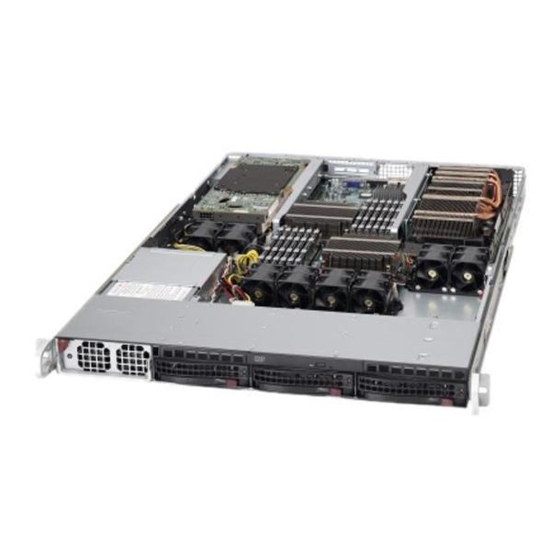
UPER ERVER 6016XT-TF/6016GT-TF/TF-TM2/TF-TC2 User's Manual Figure 6-1. Chassis: Front and Rear Views Power Supply Control Panel Hot-Swap Drive Bays (3) USB Ports Dedicated IPMI LAN Port PCI Slot LAN Ports COM Port VGA Port Control Panel The control panel (located on the front of the chassis) must be connected to the JF1 connector on the serverboard to provide you with system status indications. -
Page 61: System Fan Failure
Chapter 6: Advanced Chassis Setup System Fan Failure Fan speed is controlled by system temperature via a BIOS setting. If a fan fails, the remaining fans will ramp up to full speed. Replace any failed fan at your earli- est convenience with the same type and model (the system can continue to run with a failed fan). -
Page 62: Drive Bay Installation/Removal
UPER ERVER 6016XT-TF/6016GT-TF/TF-TM2/TF-TC2 User's Manual Figure 6-2. Removing a Fan from the Fan Tray Drive Bay Installation/Removal Accessing the Drive Bays Hard Drives: Because of their hotswap capability, you do not need to access the inside of the chassis or power down the system to install or replace hard drives. Proceed to the next section for instructions. - Page 63 Chapter 6: Advanced Chassis Setup Figure 6-3. Removing a Hard Drive Carrier Warning: Except for short periods of time (swapping hard drives), do not operate the server with the hard drive carriers removed.
- Page 64 UPER ERVER 6016XT-TF/6016GT-TF/TF-TM2/TF-TC2 User's Manual Installing a Hard Drive to the Hard Drive Carrier Remove the two screws securing the dummy drive to the carrier. Remove the dummy drive from the carrier. Install a new drive into the carrier with the printed circuit board side facing downward so that the mounting holes align with those in the carrier.
-
Page 65: Peripheral Drive Installation
Chapter 6: Advanced Chassis Setup Note: When installing the hard drive carrier that is next to the power supply, the power supply handle must be lifted before extending the hard drive carrier handle, or before inserting the hard drive carrier into the drive bay. Figure 6-5. -
Page 66: Installing The Air Shroud
UPER ERVER 6016XT-TF/6016GT-TF/TF-TM2/TF-TC2 User's Manual Installing the Air Shroud Air shrouds concentrate airfl ow to maximize fan effi ciency. The air shroud for the SC818GTQ chassis does not require screws to set up. Installing the Air Shroud Position the air shroud in the chassis as illustrated above. Align the notch (A) on the air shroud with the pin (B) on the add-on card bracket. -
Page 67: Power Supply
Chapter 6: Advanced Chassis Setup Power Supply The system includes a single 1400 watt power supply, which is auto-switching capa- ble. Power must be removed from the system when replacing the power supply. Power Supply Failure If the power supply module fails, the system will shut down and you will need to replace the module. - Page 68 UPER ERVER 6016XT-TF/6016GT-TF/TF-TM2/TF-TC2 User's Manual Notes 6-10...
-
Page 69: Chapter 7 Bios
Chapter 7: BIOS Chapter 7 BIOS Introduction This chapter describes the AMI BIOS Setup Utility for the X8DTG-DF. The AMI ROM BIOS is stored in a Flash EEPROM and can be easily updated. This chapter describes the basic navigation of the AMI BIOS Setup Utility setup screens. Starting BIOS Setup Utility To enter the AMI BIOS Setup Utility screens, press the <Delete>... -
Page 70: Starting The Setup Utility
UPER ERVER 6016XT-TF/6016GT-TF/TF-TM2/TF-TC2 User's Manual Starting the Setup Utility Normally, the only visible Power-On Self-Test (POST) routine is the memory test. As the memory is being tested, press the <Delete> key to enter the main menu of the AMI BIOS Setup Utility. From the main menu, you can access the other setup screens. - Page 71 Chapter 7: BIOS Supermicro X8DTG-DF • BIOS Build Version : This item displays the BIOS revision used in your sys- tem. • BIOS Build Date : This item displays the date when this BIOS was completed. • AMI BIOS Core Version : This item displays the revision number of the AMI BIOS Core upon which your BIOS was built.
-
Page 72: Advanced Setup Confi Gurations
UPER ERVER 6016XT-TF/6016GT-TF/TF-TM2/TF-TC2 User's Manual Advanced Setup Confi gurations Use the arrow keys to select Boot Setup and hit <Enter> to access the submenu items: BOOT Features Quick Boot If Enabled, this option will skip certain tests during POST to reduce the time needed for system boot. -
Page 73: Processor And Clock Options
Chapter 7: BIOS Hit 'Del' Message Display This feature displays "Press DEL to run Setup" during POST. The options are Enabled and Disabled. Interrupt 19 Capture Interrupt 19 is the software interrupt that handles the boot disk function. When this item is set to Enabled, the ROM BIOS of the host adaptors will "capture"... - Page 74 UPER ERVER 6016XT-TF/6016GT-TF/TF-TM2/TF-TC2 User's Manual C1E Support Select Enabled to use the feature of Enhanced Halt State. C1E signifi cantly reduces the CPU's power consumption by reducing the CPU's clock cycle and voltage during a "Halt State." The options are Disabled and Enabled. Hardware Prefetcher (Available when supported by the CPU) If set to Enabled, the hardware pre fetcher will pre fetch streams of data and instruc- tions from the main memory to the L2 cache in the forward or backward manner to...
-
Page 75: Advanced Chipset Control
Chapter 7: BIOS tion and heat dissipation. Please refer to Intel’s web site for detailed information. The options are Disable (Disable GV3) and Enable (Enable GV3). Intel® TurboMode Technology Select Enabled to use the Turbo Mode to boost system performance. The options are Enabled and Disabled. - Page 76 UPER ERVER 6016XT-TF/6016GT-TF/TF-TM2/TF-TC2 User's Manual QPI L0s and L1 This enables the QPI power state to low power. L0s and L1 are automatically selected by the motherboard. The options are Disabled and Enabled. Memory Frequency This feature forces a DDR3 frequency slower than what the system has detected. The available options are Auto, Force DDR-800, Force DDR-1066, and Force DDR-1333.
- Page 77 Chapter 7: BIOS Guardband Temperature This is the temperature which applies to the DIMM temperature threshold. Each step is in 0.5 C increment. The default is [006]. Press "+" or "-" on your keyboard to change this value. Inlet Temperature This is the temperature detected at the chassis inlet.
- Page 78 UPER ERVER 6016XT-TF/6016GT-TF/TF-TM2/TF-TC2 User's Manual Intel VT-d Select Enabled to enable Intel's Virtualization Technology support for Direct I/O VT-d by reporting the I/O device assignments to VMM through the DMAR ACPI Tables. This feature offers fully-protected I/O resource-sharing across the Intel platforms, providing the user with greater reliability, security and availability in networking and data-sharing.
- Page 79 Chapter 7: BIOS Hand-Off support. When enabled, the EHCI Interface will be changed from the BIOS- controlled to the OS-controlled. The options are Disabled and Enabled. IDE/SATA/Floppy Confi guration When this submenu is selected, the AMI BIOS automatically detects the presence of the IDE devices and displays the following items: SATA#1 Confi...
- Page 80 UPER ERVER 6016XT-TF/6016GT-TF/TF-TM2/TF-TC2 User's Manual Primary IDE Master/Slave, Secondary IDE Master/Slave, Third IDE Master, and Fourth IDE Master These settings allow the user to set the parameters of Primary IDE Master/Slave, Secondary IDE Master/Slave, Third and Fourth IDE Master slots. Hit <Enter> to activate the following submenu screen for detailed options of these items.
- Page 81 Chapter 7: BIOS Select 4 to allow the AMI BIOS to use PIO mode 4. It has a data transfer band- width of 32-Bits. Select Enabled to enable 32-Bit data transfer. DMA Mode Select Auto to allow the BIOS to automatically detect IDE DMA mode when the IDE disk drive support cannot be determined.
- Page 82 UPER ERVER 6016XT-TF/6016GT-TF/TF-TM2/TF-TC2 User's Manual the S.M.A.R.T. Select Enabled to allow the AMI BIOS to use the S.M.A.R.T. to support hard drive disk. The options are Disabled, Enabled, and Auto. 32Bit Data Transfer Select Enable to enable the function of 32-bit IDE data transfer. The options are Enabled and Disabled.
- Page 83 Chapter 7: BIOS as its I/O port address and IRQ 4 for the interrupt address. The options for Serial Port1 are Disabled, 3F8/IRQ4, 3E8/IRQ4, 2E8/IRQ3. The options for Serial Port2 are Disabled, 2F8/IRQ3, 3E8/IRQ4, and 2E8/IRQ3. Remote Access Confi guration Remote Access This allows the user to enable the Remote Access feature.
-
Page 84: Hardware Health Monitor
UPER ERVER 6016XT-TF/6016GT-TF/TF-TM2/TF-TC2 User's Manual Hardware Health Monitor This feature allows the user to monitor system health and review the status of each item as displayed. CPU Overheat Alarm This option allows the user to select the CPU Overheat Alarm setting which de- termines when the CPU OH alarm will be activated to provide warning of possible CPU overheat. - Page 85 Chapter 7: BIOS Supermicro has leveraged this feature by assigning a temperature status to certain thermal conditions in the processor (Low, Medium and High). This makes it easier for the user to understand the CPU’s temperature status, rather than by just simply seeing a temperature reading (i.e., 25 C).
- Page 86 UPER ERVER 6016XT-TF/6016GT-TF/TF-TM2/TF-TC2 User's Manual Fan1 ~ Fan 4 Reading This feature displays the fan speed readings from fan interfaces Fan1 through Fan5. CPU1 Vcore, CPU2 Vcore, +5Vin, +12Vcc (V), VP1 DIMM, VP2 DIMM, 3.3Vcc (V), and Battery Voltage ACPI Confi guration Use this feature to confi...
-
Page 87: View Bmc System Event Log
Chapter 7: BIOS Status of BMC Baseboard Management Controller (BMC) manages the interface between system management software and platform hardware. This is an informational feature which returns the status code of the BMC micro controller. View BMC System Event Log This feature displays the BMC System Event Log (SEL). - Page 88 UPER ERVER 6016XT-TF/6016GT-TF/TF-TM2/TF-TC2 User's Manual • Total Number of Entries • SEL Entry Number • SEL Record ID • SEL Record Type • Timestamp, Generator ID • Event Message Format User • Event Sensor Type • Event Sensor Number, • Event Dir Type •...
- Page 89 Chapter 7: BIOS Channel Number - Enter the channel number for the SET LAN Confi g com- mand. This is initially set to [1]. Press "+" or "-" on your keyboard to change the Channel Number. Channel Number Status - This feature returns the channel status for the Channel Number selected above: "Channel Number is OK"...
- Page 90 UPER ERVER 6016XT-TF/6016GT-TF/TF-TM2/TF-TC2 User's Manual Parameter Selector Use this feature to select the parameter of your IP Address confi guration. IP Address The BIOS will automatically enter the IP address of this machine; however it may be over-ridden. IP addresses are 6 two-digit hexadecimal numbers (Base 16, 0 ~ 9, A, B, C, D, E, F) separated by dots.
- Page 91 Chapter 7: BIOS SEL PEF Confi guration Set PEF Confi guration Set this feature to confi gure the Platform Event Filter (PEF). PEF interprets BMC events and performs actions based on pre-determined settings or 'traps' under IPMI 1.5 specifi cations. For example, powering the system down or sending an alert when a triggering event is detected.
-
Page 92: Dmi Event Log
UPER ERVER 6016XT-TF/6016GT-TF/TF-TM2/TF-TC2 User's Manual Event Message for PEF Action - This enables of disables Event Messages for PEF action. Refer to Table 24.6 of the IPMI 1.5 Specifi cation for more informa- tion at www.intel.com. The options are Disabled and Enabled. BMC Watch Dog Timer Action Allows the BMC to reset or power down the system if the operating system hangs or crashes. -
Page 93: Security Settings
Chapter 7: BIOS Security Settings The AMI BIOS provides a Supervisor and a User password. If you use both pass- words, the Supervisor password must be set fi rst. Supervisor Password This item indicates if a Supervisor password has been entered for the system. "Not Installed"... -
Page 94: Boot Confi Guration
UPER ERVER 6016XT-TF/6016GT-TF/TF-TM2/TF-TC2 User's Manual Clear User Password (Available only when User Password has been set) This item allows you to clear a user password after it has been entered. Password Check This item allows you to check a password after it has been entered. The options are Setup and Always. -
Page 95: Exit Options
Chapter 7: BIOS Hard Disk Drives This feature allows the user to specify the boot sequence from all available hard disk drives. The settings are Disabled and a list of all hard disk drives that have been detected (i.e., 1st Drive, 2nd Drive, 3rd Drive, etc). •... - Page 96 UPER ERVER 6016XT-TF/6016GT-TF/TF-TM2/TF-TC2 User's Manual Save Changes and Exit When you have completed the system confi guration changes, select this option to leave the BIOS Setup Utility and reboot the computer, so the new system con- fi guration parameters can take effect. Select Save Changes and Exit from the Exit menu and press <Enter>.
-
Page 97: Appendix A Bios Error Beep Codes
Appendix A: BIOS Error Beep Codes Appendix A BIOS Error Beep Codes During the POST (Power-On Self-Test) routines, which are performed each time the system is powered on, errors may occur. Non-fatal errors are those which, in most cases, allow the system to continue the boot-up process. - Page 98 UPER ERVER 6016XT-TF/6016GT-TF/TF-TM2/TF-TC2 User's Manual Notes...
-
Page 99: Appendix B Installing Windows
Appendix B: Installing Windows Appendix B Installing Windows After all hardware components have been installed, you must fi rst confi gure Intel South Bridge RAID Settings before you install the Windows OS and other software drivers. To confi gure RAID settings, please refer to RAID Confi guration User Guides posted on our web site at www.supermicro.com/support/manuals. - Page 100 UPER ERVER 6016XT-TF/6016GT-TF/TF-TM2/TF-TC2 User's Manual B-2 Installing Windows for a Non-RAID System Insert Microsoft's Windows XP/Windows 2003 setup CD in the CD drive and the system will start booting up from the CD. Continue with the OS installation. The Windows OS Setup screen will display. From the Windows setup screen, press the <Enter>...
-
Page 101: Appendix C System Specifi Cations
Appendix C: System Specifi cations Appendix C System Specifi cations Processors Two Intel Xeon 5500 series processors Note: Please refer to our web site for a complete listing of supported processors. Chipset Intel 5520 + ICH10R BIOS 32 Mb AMIBIOS® SPI Flash ROM Memory Capacity Twelve DIMM sockets supporting up to 96 GB of registered ECC DDR3- 1333/1066/800 SDRAM or up to 24 GB of unbuffered ECC/non-ECC DDR3-... - Page 102 UPER ERVER 6016XT-TF/6016GT-TF/TF-TM2/TF-TC2 User's Manual Serverboard X8DTG-DF (proprietary ATX form factor) Dimensions: 16.64" x 7.74" (423 x 197 mm) Chassis SC818GTQ-1400B (1U rackmount) Dimensions: (WxHxD) 17.2 x 1.7 x 28.2 in. (437 x 43 x 716 mm) Weight Gross (Bare Bone): 47 lbs. (21.4 kg.) System Cooling Four sets of 4-cm counter-rotating cooling fans (fan speed controlled by BIOS setting) and two sets of 4-cm counter-rotating cooling fans for GPUs (6016GT...
- Page 103 Appendix C: System Specifi cations Safety: CSA/EN/IEC/UL 60950-1 Compliant, UL or CSA Listed (USA and Canada), CE Marking (Europe) California Best Management Practices Regulations for Perchlorate Materials: This Perchlorate warning applies only to products containing CR (Manganese Dioxide) Lithium coin cells. “Perchlorate Material-special handling may apply. See www.dtsc.ca.gov/hazardouswaste/perchlorate”...
- Page 104 UPER ERVER 6016XT-TF/6016GT-TF/TF-TM2/TF-TC2 User's Manual (continued from front) The products sold by Supermicro are not intended for and will not be used in life support systems, medical equipment, nuclear facilities or systems, aircraft, aircraft devices, aircraft/emergency com- munication devices or other critical systems whose failure to perform be reasonably expected to result in signifi...
Need help?
Do you have a question about the SUPERSERVER 6016XT-TF and is the answer not in the manual?
Questions and answers