Moxa Technologies EtherDevice EDS-P206A-4PoE Series Hardware Installation Manual
Hide thumbs
Also See for EtherDevice EDS-P206A-4PoE Series:
- Quick installation manual (17 pages) ,
- Hardware installation manual (15 pages)

Subscribe to Our Youtube Channel
Related Manuals for Moxa Technologies EtherDevice EDS-P206A-4PoE Series


Summary of Contents for Moxa Technologies EtherDevice EDS-P206A-4PoE Series
-
Page 1: Moxa Etherdevice Switch
Moxa EtherDevice Switch EDS-P206A-4PoE Series Hardware Installation Guide First Edition, July 2010 © 2010 Moxa Inc. All rights reserved. Reproduction without permission is prohibited. P/N: 1802002060010... -
Page 2: Package Checklist
Overview The EDS-P206A-4PoE series industrial Ethernet switches are entry-level industrial 6-port PoE Ethernet switches that support IEEE 802.3, IEEE 802.3u, and IEEE 802.3x, with 10/100M, full/half-duplex, MDI/MDIX auto-sensing, IEEE 802.3af, and IEEE 802.3at. The EDS-P206A-4PoE series provides 24/48 VDC redundant power inputs that can be connected simultaneously to a live DC power source. - Page 3 Features High-watt Power-over-Ethernet Up to 30 watts per PoE port Active circuit protection Auto disconnection for over-voltage or under-voltage Power consumption detection and classification High Performance Network Switching Technology 10/100BaseT(X) (RJ45 connector), 100BaseFX (SC/ST connector, multi/single-mode) 10/100M, Full/Half-Duplex, MDI/MDIX auto-sensing IEEE 802.3/802.3u/802.3x Store and Forward switching process type, 1K address entries Rugged Design...
- Page 4 EDS-P206A-4PoE (Standard) Panel Layouts Front Panel View Grounding screw Terminal block for power input P1/P2 PoE+ Heat dissipation orifices DIP switches Power input P1 LED Power input P2 LED PoE LED 10/100BaseT(X) port EDS-P206A-4PoE TP port’s 10/100 Mbps Top Panel View 10.
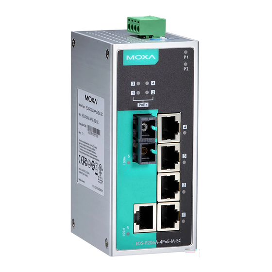
- Page 5 EDS-P206A-4PoE-M-SC/ST Panel Layouts NOTE: The EDS-P206A-4PoE-S-SC/ST are identical in appearance to the EDS-P206A-4PoE-M-SC/ST. EDS-P206A- EDS-P206A- 4PoE-M-ST 4PoE-M-SC Front Panel View Grounding screw Terminal block for power input P1/P2 Heat dissipation orifices DIP switches Power input P1 LED Power input P2 LED PoE LED 10/100BaseT(X) port Top Panel View...
- Page 6 EDS-P206A-4PoE-MM-SC/ST Panel Layouts NOTE: The EDS-P206A 4PoE-SS-SC/ST are identical in appearance to the EDS-P206A-4PoE- MM-SC/ST. EDS-P206A- EDS-P206A- 4PoE-MM-ST 4PoE-MM-SC Front Panel View Grounding screw Terminal block for power input P1/P2 Heat dissipation orifices DIP Switches Power input P1 LED Power input P2 LED PoE LED 10/100BaseT(X) port Top Panel View...
-
Page 7: Mounting Dimensions (Unit = Mm)
Mounting Dimensions (unit = mm) 23.5 30.5 50.3 30.5 78.8 DIN-Rail Mounting The aluminum DIN-Rail attachment plate should already be fixed to the back panel of the EDS when you take it out of the box. If you need to reattach the DIN-Rail attachment plate, make sure the stiff metal spring is situated towards the top, as shown in the figures below. -
Page 8: Wall Mounting (Optional)
Wall Mounting (optional) For some applications, you will find it convenient to mount the EDS-P206A-4PoE on the wall, as shown in the following figures. STEP 1: Remove the aluminum DIN-Rail attachment plate from the plate ⇒ EDS-P206A-4PoE’s rear panel, and then attach the wall mount plates as shown bottom plate... -
Page 9: Grounding The Etherdevice Switch
WARNING Safety First! Calculate the maximum possible current in each power wire and common wire. Observe all electrical codes dictating the maximum current allowable for each wire size. If the current goes above the maximum ratings, the wiring could overheat, causing serious damage to your equipment. You should also pay attention to the following points: Use separate paths to route wiring for power and devices. -
Page 10: Communication Connections
ATTENTION Before connecting the EtherDevice Switch to the DC power inputs, make sure the DC power source voltage is stable. Communication Connections The EDS-P206A-4PoE switches have 6, 7, or 8 10/100BaseT(X) Ethernet ports, and 2, 1, or 0 (zero) 100BaseFX multi/single-mode (SC/ST-type connector) fiber ports. -
Page 11: 100Basefx Ethernet Port Connection
100BaseFX Ethernet Port Connection The concept behind the SC/ST port and cable is quite straightforward. Suppose you are connecting devices I and II; contrary to electrical signals, optical signals do not require a circuit in order to transmit data. Consequently, one of the optical lines is used to transmit data from device I to device II, and the other optical line is used transmit data from device II to device I, for full-duplex transmission. -
Page 12: Dip Switch Settings
DIP Switch Settings The default setting for each DIP Switch is OFF. The following table explains the effect of setting the DIP Switches to the ON positions. DIP Switch Setting Description Serves no function (reserved for future use). – – Enables broadcast storm protection Disables broadcast storm protection ATTENTION... -
Page 13: Auto Mdi/Mdi-X Connection
Auto MDI/MDI-X Connection The Auto MDI/MDI-X function allows users to connect the EDS’s 10/100BaseTX ports to any kind of Ethernet device, without needing to pay attention to the type of Ethernet cable being used for the connection. This means that you can use either a straight-through cable or cross-over cable to connect the EDS to Ethernet devices. -
Page 14: Specifications
as required by the IEEE 802.3u standard. Specifications Technology Standards IEEE 802.3 for 10BaseT, IEEE 802.3u for 100BaseT(X) and 100BaseFX, IEEE 802.3x for Flow Control IEEE 802.3af for PoE IEEE 802.3at for PoE+ Processing Type Store and Forward Flow Control IEEE 802.3x flow control, back pressure flow control Interface RJ45 Ports... - Page 15 Environmental Limits Operating Temperature Standard models: 0 to 60°C (32 to 140°F) Wide temp. models: -40 to 75°C (-40 to 167°F) Storage Temperature -40 to 85°C (-40 to 185°F) Ambient Relative 5 to 95% (non-condensing) Humidity Regulatory Approvals FCC Part 15, CISPR (EN55022) class A EN61000-4-2 (ESD), Level 3 EN61000-4-3 (RS), Level 3 EN61000-4-4 (EFT), Level 3...
Need help?
Do you have a question about the EtherDevice EDS-P206A-4PoE Series and is the answer not in the manual?
Questions and answers