
Related Manuals for Moxa Technologies EDS-P206A-4PoE-SS-SC


Summary of Contents for Moxa Technologies EDS-P206A-4PoE-SS-SC
- Page 1 EDS-P206A-4PoE Series Hardware Installation Guide Moxa EtherDevice Switch Third Edition, April 2014 2014 Moxa Inc. All rights reserved. P/N: 1802002060012...
-
Page 2: Package Checklist
Overview The EDS-P206A-4PoE series industrial Ethernet switches are entry-level industrial 6-port PoE Ethernet switches that support IEEE 802.3, IEEE 802.3u, and IEEE 802.3x, with 10/100M, full/half-duplex, MDI/MDIX auto-sensing, IEEE 802.3af, and IEEE 802.3at. The EDS-P206A-4PoE series provides 24/48 VDC redundant power inputs that can be connected simultaneously to a live DC power source. - Page 3 EDS-P206A-4PoE (Standard) Panel Layouts 1. Grounding screw 2. Terminal block for power input P1/P2 3. Heat dissipation vents 4. DIP switches 5. Power input P1 LED 6. Power input P2 LED 7. PoE LED 8. 10/100BaseT(X) port 9. TP port’s 10/100 Mbps LED 10.
- Page 4 EDS-P206A-4PoE-M-SC/ST Panel Layouts NOTE: The EDS-P206A-4PoE-S-SC/ST are identical in appearance to the EDS-P206A-4PoE-M-SC/ST. 1. Grounding screw 2. Terminal block for power input P1/P2 3. Heat dissipation vents 4. DIP switches 5. Power input P1 LED 6. Power input P2 LED 7.
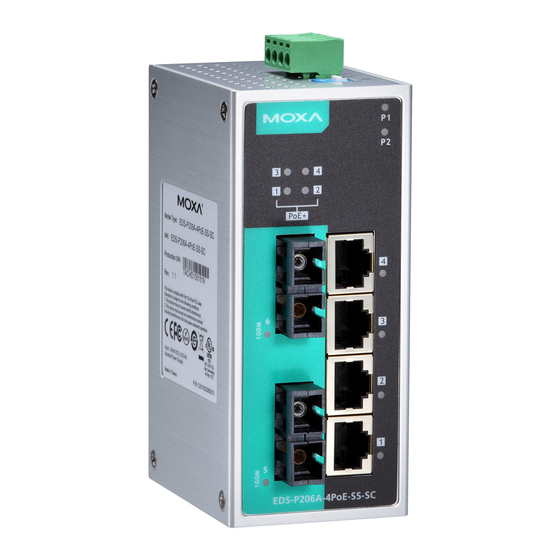
- Page 5 EDS-P206A-4PoE-MM-SC/ST Panel Layouts NOTE: The EDS-P206A 4PoE-SS-SC/ST are identical in appearance to the EDS-P206A-4PoE- MM-SC/ST. 1. Grounding screw 2. Terminal block for power input P1/P2 3. Heat dissipation vents 4. DIP Switches 5. Power input P1 LED 6. Power input P2 LED 7.
-
Page 6: Mounting Dimensions
Mounting Dimensions Unit = mm (inch) DIN-Rail Mounting The aluminum DIN-Rail attachment plate should already be fixed to the back panel of the EDS when you take it out of the box. If you need to reattach the DIN-Rail attachment plate, make sure the stiff metal spring is situated towards the top, as shown in the figures below. -
Page 7: Wall Mounting (Optional)
Wall Mounting (optional) For some applications, you will find it convenient to mount the EDS-P206A-4PoE on the wall, as shown in the following figures. STEP 1: Remove the aluminum DIN-Rail attachment plate from the EDS-P206A-4PoE’s rear panel, and then attach the wall mount plates as shown in the diagram at the right. -
Page 8: Grounding The Etherdevice Switch
WARNING Safety First! Calculate the maximum possible current in each power wire and common wire. Observe all electrical codes dictating the maximum current allowable for each wire size. If the current goes above the maximum ratings, the wiring could overheat, causing serious damage to your equipment. -
Page 9: Communication Connections
ATTENTION Before connecting the EtherDevice Switch to the DC power inputs, make sure the DC power source voltage is stable. Communication Connections The EDS-P206A-4PoE switches have 6, 7, or 8 10/100BaseT(X) Ethernet ports, and 2, 1, or 0 (zero) 100BaseFX multi/single-mode (SC/ST-type connector) fiber ports. - Page 10 RJ45 (8-pin) to RJ45 (8-pin) Straight-Through Cable Wiring RJ45 (8-pin) to RJ45 (8-pin) Cross-Over Cable Wiring NOTE If the PD only supports MDI mode (V+, V+, V-, V- for pins 1, 2, 3, 6), choose a cross-over Ethernet cable to connect the PD and the EDS switch.
-
Page 11: Redundant Power Inputs
ST-Port Pinouts ST-Port to ST-Port Cable Wiring ATTENTION This is a Class 1 Laser/LED product. To avoid causing serious damage to your eyes, do not stare directly into the Laser Beam. Redundant Power Inputs Both power inputs can be connected simultaneously to live DC power sources. -
Page 12: Auto Mdi/Mdi-X Connection
Blinking Data is being transmitted at 10 Mbps. TP Port’s 10 Mbps link is inactive. TP port’s 100 Mbps link is active. GREEN Blinking Data is being transmitted at 100 Mbps. TP Port’s 100 Mbps link is inactive. FX port’s 100 Mbps link is active. 100M GREEN Blinking Data is being transmitted at 100 Mbps. -
Page 13: Auto-Negotiation And Speed Sensing
Auto-Negotiation and Speed Sensing All of the EDS’s RJ45 Ethernet ports independently support auto-negotiation for speeds in the 10BaseT and 100BaseTX modes, with operation according to the IEEE 802.3u standard. This means that some nodes could be operating at 10 Mbps, while at the same time, other nodes are operating at 100 Mbps. - Page 14 Power Input Voltage 24/48 VDC Input Current 5.5/2.6 A Connection Removable 4-contact terminal block Overload Current 12 A Protection Reverse Polarity Present Protection Conformance to UL Always use an “isolated power supply” to standards conform to the UL 508 standard. Note: We strongly recommend using an isolated power supply with maximum output current of 7.5 A due to the power de-rating issue of the power supply at high operating temperatures.
Need help?
Do you have a question about the EDS-P206A-4PoE-SS-SC and is the answer not in the manual?
Questions and answers