Table of Contents
Advertisement
Quick Links
Download this manual
See also:
User Manual
Advertisement
Table of Contents

Related Manuals for Moxa Technologies EtherDevice EDS-P510A-8PoE Series


Summary of Contents for Moxa Technologies EtherDevice EDS-P510A-8PoE Series
-
Page 1: Hardware Installation Guide
Moxa EtherDevice Switch EDS-P510A-8PoE Series Hardware Installation Guide First Edition, January 2013 2013 Moxa Inc. All rights reserved. P/N: 1802005100020... -
Page 2: Package Checklist
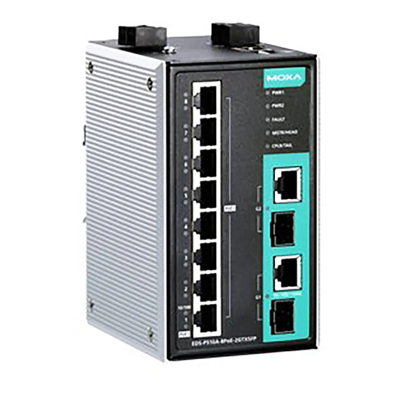
Overview The Moxa EDS-P510A-8PoE series switches are Gigabit managed PoE+ Ethernet switches that come standard with eight 10/100BaseT(X), 802.3af (PoE) and 802.3at (PoE+) compliant Ethernet ports and two combo Gigabit Ethernet ports. The EDS-P510A-8PoE Ethernet switches provide up to 30 watts of power per PoE+ port in standard mode, and allow high power output of up to 36 watts for industrial heavy-duty PoE devices, such as weather-proof IP surveillance cameras with wipers/heaters, high-performance wireless access points, and rugged IP... - Page 3 Panel Views of EDS-P510A-8PoE Front Panel View 1. Power input PWR1 LED 2. Power input PWR2 LED 3. Fault LED 4. MSTR/HEAD LED 5. CPLR/TAIL LED 6. 1000Mbps copper port of the combo port 7. 100/1000Mbps SFP port of the combo port 8.
-
Page 4: Mounting Dimensions (Unit = Mm)
Mounting Dimensions (unit = mm) DIN-Rail Mounting The aluminum DIN-Rail attachment plate should already be fixed to the back panel of the EDS-P510A-8PoE when you take it out of the box. If you need to reattach the DIN-Rail attachment plate to the EDS-P510A-8PoE, make sure the stiff metal spring is situated towards the top, as shown by the following figures. -
Page 5: Wall Mounting (Optional)
Wall Mounting (Optional) For some applications, you will find it convenient to mount Moxa EDS-P510A-8PoE on the wall, as shown in the following illustrations: STEP 1—Remove the aluminum DIN-Rail attachment plate from the rear panel of the EDS-P510A -8PoE, and then attach the wall mount plates with M3 screws, as shown in the... -
Page 6: Wiring Requirements
Wiring Requirements WARNING Do not disconnect modules or wires unless power has been switched off or the area is known to be non-hazardous. The devices may only be connected to the supply voltage shown on the type plate. The devices are designed for operation with a Safety Extra-Low Voltage. -
Page 7: Wiring The Relay Contact
Grounding the Moxa EDS-P510A-8PoE Grounding and wire routing help limit the effects of noise due to electromagnetic interference (EMI). Run the ground connection from the ground screw to the grounding surface prior to connecting devices. ATTENTION This product is intended to be mounted to a well-grounded mounting surface such as a metal panel. -
Page 8: Wiring The Digital Inputs
Wiring the Digital Inputs The EDS-P510A-8PoE has one digital input. The DI consists of two contacts on the terminal block connector on the EDS-P510A-8PoE’s top-right panel. The top and front views of one of the terminal block connectors are shown here. STEP 1: Insert the negative (ground)/positive DI wires into the ┴/I terminals, respectively. -
Page 9: Led Indicators
“Turbo Ring” DIP Switch Settings DIP 1 DIP 2 DIP 3 DIP 4 ON: Enables this ON: Enables the ON: Activates DIP EDS as the Ring default “Ring switches 1, 2, 3 to Master. Coupling” ports. configure “Turbo Reserved for Ring”... - Page 10 Color State Description When the switch is set as the Master of the Turbo Ring, or as the Head of the Turbo Chain. The switch has become the Ring Master of the Turbo Ring, or the Head MSTR/HEAD GREEN Blinking of the Turbo Chain, after the Turbo Ring or the Turbo Chain is down.
-
Page 11: Switch Properties
Specifications of EDS-P510A-8PoE Series Technology Standards IEEE 802.3af/at for Power-over-Ethernet, IEEE 802.3 for 10BaseT, IEEE 802.3u for 100BaseT(X) and 100Base FX, IEEE 802.3ab for 1000BaseT(X), IEEE 802.3z for 1000BaseSX/LX/LHX/ZX, IEEE 802.3x for Flow Control, IEEE 802.1D for Spanning Tree Protocol, IEEE 802.1w for Rapid STP, IEEE 802.1Q for VLAN Tagging, IEEE 802.1p for Class of Service,... - Page 12 Power Input Voltage 48 VDC (46 to 50 VDC), redundant dual inputs Connection Two removable 6-pin terminal blocks Overload Current Present Protection Reverse Polarity Present Protection Physical Characteristics Casing IP30 protection, metal case Dimensions 80.2 × 135 × 105 mm (3.16 × 5.31 × 4.13 in) Weight 1030 g Installation...
Need help?
Do you have a question about the EtherDevice EDS-P510A-8PoE Series and is the answer not in the manual?
Questions and answers