Table of Contents
Advertisement
Quick Links
Download this manual
See also:
User Manual
Advertisement
Table of Contents

Related Manuals for ADLINK Technology PCIS-8580-4S


Summary of Contents for ADLINK Technology PCIS-8580-4S
- Page 1 PCIS-8580-4S PCIS-8580-13S User’s Manual Manual Rev. 2.04 Revision Date: November 15, 2010 Part No: 50-15054-1020 Advance Technologies; Automate the World.
- Page 2 Copyright 2009, 2010 ADLINK TECHNOLOGY INC. All Rights Reserved. The information in this document is subject to change without prior notice in order to improve reliability, design, and function and does not represent a commitment on the part of the manufacturer.
- Page 3 Address: 5215 Hellyer Avenue, #110, San Jose, CA 95138, USA Tel: +1-408-360-0200 Toll Free: +1-800-966-5200 (USA only) Fax: +1-408-360-0222 Email: info@adlinktech.com ADLINK Technology (China) Co., Ltd. Address: (201203) 300 Fang Chun Rd., Zhangjiang Hi-Tech Park, Pudong New Area, Shanghai, 201203 China Tel: +86-21-5132-8988 Fax:...
- Page 4 Address: 84 Genting Lane #07-02A, Cityneon Design Centre, Singapore 349584 Tel: +65-6844-2261 Fax: +65-6844-2263 Email: singapore@adlinktech.com ADLINK Technology Singapore Pte. Ltd. (Indian Liaison Office) Address: No. 1357, "Anupama", Sri Aurobindo Marg, 9th Cross, JP Nagar Phase I, Bangalore - 560078, India Tel: +91-80-65605817 Fax: +91-80-22443548 Email:...
-
Page 5: Table Of Contents
Table of Contents..............i List of Tables................iii List of Figures ................ iv 1 Introduction ................ 1 Features................2 PCIS-8580-4S ..............2 PCIS-8580-13S ............... 2 Applications ................. 2 Specifications............... 3 LPCI-8575 PCI-PCI Expansion Card ......3 RK-8005 Expansion chassis ........... 4 RK-8014 Expansion chassis ........... - Page 6 RK-8005................23 Mechanical Drawing of RK-8005 ........23 BP-8014 ................24 Backplane Architecture ..........24 Jumpers and Connectors ..........25 RK-8014................26 Mechanical Drawing of RK-8014 ........26 ACL-PCIEXT-2..............27 Pin Assignment of ACL-PCIEXT-2 ....... 27 Table of Contents...
-
Page 7: List Of Tables
List of Tables Table 1-1: Power requirements ..........3 Table 3-1: Jumpers and connectors on the LPCI-8575 ... 15 Table 3-2: JP1 Settings ............16 Table 3-3: JP2 Settings ............16 Table 3-4: JP3 Settings ............17 Table 3-5: D2 Display .............. 18 Table 3-6: Top side jumpers and connectors ...... - Page 8 Figure 2-3: Install your PCI cards into the expansion chassis (using the PCIS-8580-4S as an example) ......11 Figure 2-4: Connect you host computer and expansion chassis (us- ing the PCIS-8580-4S as an example) ....12 Figure 3-1: Operation theory of PCIS-8580 PCI-to-PCI expansion system ..............13 Figure 3-2: Concept of the serialized PCI bridge .......
-
Page 9: Introduction
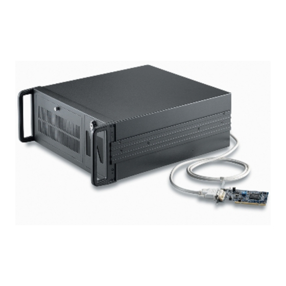
The ADLINK PCIS-8580 PCI-to-PCI expansion system is com- posed of three major components: a PCI expansion card (LPCI- 8575), an expansion chassis (RK-8005 for PCIS-8580-4S or RK- 8014 for PCIS-8580-13S), and a cable (ACL-PCIEXT-2). The PCI expansion card is the core of this system. It acts as a PCI bridge... -
Page 10: Features
1.1 Features PCIS-8580-4S PCI local bus specification Rev 2.2 compliant PCI bridge architecture specification Rev 1.2 compliant Provides 4 extended half-size PCI slots Full 32-bit/33MHz PCI bandwidth expansion (132MB/s) Maximal 10m expansion distance Complete hardware and software transparency ... -
Page 11: Specifications
1.3 Specifications LPCI-8575 PCI-PCI Expansion Card PCI local bus specification Rev 2.2 compliant PCI bridge architecture specification Rev 1.2 compliant Supports both 5V and 3.3V PCI bus Data throughput: full 32-bit/33MHz PCI bandwidth (132MB/ I/O connector: DVI-D 24-pin connector ... -
Page 12: Rk-8005 Expansion Chassis
RK-8005 Expansion chassis Dimensions: 122mm(W) x 195mm(H) x 260mm(D) Weight: 3.2 Kg (7.04lb) Backplane: 5x 32-bit/33MHz half-size PCI slots 1 slot for expansion card 4 slots available for PCI cards Front-panel indicators Power indicator (Red LED) ... -
Page 13: Rk-8014 Expansion Chassis
RK-8014 Expansion chassis Dimensions: 438.5mm(W) x 177mm(H) x 448.5mm(D) Weight: 12 kg (26.4lb) Backplane: 14x 32-bit/33MHz full-size PCI slots 1 slot for expansion card 13 slots available for PCI cards Front-panel indicators Power indicator (Red LED) ... - Page 14 Introduction...
-
Page 15: Installation
This chapter outlines the contents of package, describes unpack- ing information, and describes how to set up the PCIS-8580 PCI- to-PCI expansion system and install your PCI cards. 2.1 Content of package PCIS-8580-4S package includes the following items: One LPCI-8575 in a individual carton ... -
Page 16: Unpacking
2.2 Unpacking The ADLINK PCIS-8580 system contains some electro-static sen- sitive components that can be easily be damaged by static elec- tricity. For this reason, the card and chassis should be handled on a grounded anti-static mat and the operator should wear an anti- static wristband during the unpacking and installation procedure. -
Page 17: Driver Installation
Figure 2-1: Install the PCI expansion card into your host system Driver Installation After installing the PCI expansion card into your host computer, now you can turn on your computer and install the driver of PCI expansion card. Please follow the following steps to finish the driver installation. -
Page 18: Install Your Pci Card Into The Expansion Chassis
Install your PCI Card into the Expansion Chassis The PCIS-8580 expansion chassis can accommodate 4 additional PCI slots (PCIS-8580-4S) or 13 additional PCI slots (PCIS-8580- 13S). This section illustrates the procedures to install your PCI cards into the expansion chassis. -
Page 19: Figure 2-3: Install Your Pci Cards Into The Expansion Chassis (Using The Pcis-8580-4S As An Example)
2. Plug you PCI cards into the expansion chassis and screw them to the chassis. 3. Put the top cover and tighten the screws. Figure 2-3: Install your PCI cards into the expansion chassis (using the PCIS-8580-4S as an example) Installation... -
Page 20: Connect To Expansion Chassis
Please DO NOT use standard DVI cable to con- nect your host computer and the expansion chassis. Figure 2-4: Connect you host computer and expansion chassis (using the PCIS-8580-4S as an example) Power-on Sequence To make the PCI-to-PCI expansion system works well, you need to follow a correct power-on sequence for both expansion chassis and host computer. -
Page 21: Hardware Overview
Hardware Overview This chapter illustrates the basic hardware architecture of each component in the ADLINK PCIS-8580 PCI-to-PCI expansion sys- tem. 3.1 System Architecture This section describes the operation theory and technology of the PCIS-8580 PCI-to-PCI expansion system. Operation Theory Figure 3-1: Operation theory of PCIS-8580 PCI-to-PCI expansion system The PCIS-8580 PCI-to-PCI expansion system utilizes the state-of- art StarFabric technology as the groundwork for extending the PCI bus. -
Page 22: Lpci-8575 Pci Expansion Card
3.2 LPCI-8575 PCI Expansion Card This section describes the basic function, bus architecture and jumper settings of the PCI expansion module LPCI-8575. Functional Block The LPCI-8575 expansion module is basically a PCI-to-PCI bridge. The PCI-to-PCI bridge function in the LPCI-8575 supports legacy address routed traffic, which provides 100% capability with PCI drivers, application software, BIOS, O/Ss, etc. -
Page 23: Jumper Settings For Lpci-8575
Jumper Settings for LPCI-8575 The following figure shows the locations of jumpers and the con- nector. Figure 3-3: Jumpers and connectors on the LPCI-8575 Jumper / Connector / LED Descriptions A DVI-D connector for the serial link for PCI-to-PCI expansion. Please DO NOT connect CN1 to any monitor or video device. -
Page 24: Table 3-2: Jp1 Settings
adopts a spread-spectrum clock generator to help user to deal with this difficult task. Spread spectrum clocking speeds up and slows down the clock within a few percent of its fundamental frequency. By reducing the peak amplitudes, the system will more likely meet EMI emission compliance standards. -
Page 25: Table 3-4: Jp3 Settings
Setting Auto detection mode disabled, force to 33MHz. PCI bus is forced to operate at 33 MHz. If your extended system is 66MHz capable, please switch JP2 to 1-2 contact. (Default) Table 3-3: JP2 Settings Peripheral / System Slot Selection, JP3 LPCI-8575 is a dual purpose PCI-to-PCI expansion module. -
Page 26: Table 3-5: D2 Display
Serial Link Status LED Connector, JP4 The serial link status is shown on LED D2. LPCI-8575 also pro- vides a LED connector for user’s applications. The pin assign- ment of JP4 is shown in the following figure. Anode Cathode Serial Link Status LED, D2 The LED D2 shows the serial link status. -
Page 27: Backplane Architecture
3.3 BP-8005 This section describes the architecture and jumper settings of the BP-8005 backplane. The BP-8005 is for PCIS-8580-4S and is pre- installed in the RK-8005 chassis. Backplane Architecture The BP-8005 backplane provides 1 system slot and 4 available PCI peripheral slots. The system slot is occupied by a pre-installed... -
Page 28: Figure 3-4: Top View Of Bp-8005 Backplane
LPCI-8575 PCI expansion card. The rest PCI slots are available for any 5V PCI peripheral cards. Figure 3-4: Top view of BP-8005 backplane Hardware Overview... -
Page 29: Figure 3-5: Bottom View Of Bp-8005 Backplane
Figure 3-5: Bottom view of BP-8005 backplane Hardware Overview... -
Page 30: Jumpers And Connectors
Jumpers and Connectors Jumpers and connectors on the top side JP/CN Ended Voltage Out Description +12V, GND Fan connector for 12V fan +5V, GND LED connector +12V, GND Fan connector for 12V fan Table 3-6: Top side jumpers and connectors Jumpers and connectors on the bottom side JP/CN Ended Voltage Out... -
Page 31: Mechanical Drawing Of Rk-8005
3.4 RK-8005 RK-8005 is a robust industrial chassis for accommodating the BP- 8005 backplane. The RK-8005 is a small, compact chassis (122mm x 195mm x 260mm) with a built-in 200W universal AC power supply. The RK-8005 is provided with a wall-mount kit so you can place it in many different environments. -
Page 32: Backplane Architecture
3.5 BP-8014 This section describes the architecture and jumper settings of the BP-8014 backplane. The BP-8014 is for PCIS-8580-13S and is pre-installed in the RK-8014 chassis. Backplane Architecture The BP-8014 backplane provides 1 system slot and 13 available PCI peripheral slots. The system slot is occupied by a pre-installed LPCI-8575 PCI expansion card. -
Page 33: Jumpers And Connectors
Jumpers and Connectors JP/CN Ended Voltage Out Description 3.3V,±12V,5V ATX POWER connector FAN4 12V, GND Fan connector for 12V fan FAN5 12V, GND Fan connector for 12V fan FAN6 12V, GND Fan connector for 12V fan ATX POWER ENABLE 5V, GND POWER-OK status connector 5V, GND LED connector... -
Page 34: Mechanical Drawing Of Rk-8014
3.6 RK-8014 RK-8014 is a robust industrial chassis for accommodating the BP- 8014 backplane. The RK-8014 is a 19” rack-mount chassis with a built-in 400W universal AC power supply. Mechanical Drawing of RK-8014 Figure 3-8: Mechanical drawing of RK-8014 Hardware Overview... -
Page 35: Acl-Pciext-2
3.7 ACL-PCIEXT-2 ACL-PCIEXT-2 is the cable connecting the host computer and the expansion chassis. It is carefully designed to transmit 622Mbps LVDS signals. ACL-PCI-EXT-2 contains 8 pairs of shielding twisted copper wires and 2 DVI-D 24-pin connectors. For users who need longer expansion distance, optional ACL-PCIEXT-5 (5m) and ACL-PCIEXT-10 (10m) are provided. - Page 36 Hardware Overview...
Need help?
Do you have a question about the PCIS-8580-4S and is the answer not in the manual?
Questions and answers