Table of Contents
Advertisement
Quick Links
Download this manual
See also:
User Manual
Welcome
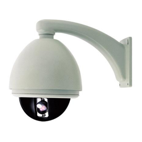
Thank you for purchasing DM870 high speed dome.
This series speed dome is newly upgraded with AMP connector for easier installation and black liner for discreet
surveillance. Its powerful functions make it a state-of-the-art speed dome, and it will fulfill your wide range
professional security surveillance need.
Features:
Backup Memory, parameters memory is designed to locate on the PCB board in the housing, settings will
l
remain when change PTZ module.
Auto run the assigned function after a period of idling
l
8 slot scheduled various function
l
220 presets, 4 sequences of 32 presets each, 4 patterns with min. 180 seconds each, 4 auto scans, 8
l
regions, up to 8 privacy masks.
On screen compass and pan/tilt degrees indication.
l
With RS485, Manchester, Bi-phase or Coaxitron control interface.
l
8 privacy masks.
l
With dome, preset, pattern, sequence and pan titles, the titles can be set to not display, display or display for
l
a period of time.
Color/mono auto, manual or switch at a set time. (for day/night models).
l
With 4000V video, data and power lightning proof.
l
Hi-accuracy motor drive with 0.1 degree preset accuracy, min. 0.1 degree moving without any vibration.
l
360 continuous pan, 90 tilt with auto flip.
l
Built in DSP camera, with auto focus, auto BLC, auto light control, auto white balance etc. functions.
l
Informative Chinese/English OSD menu, all the functions can be set via OSD menu.
l
-1-
Advertisement
Table of Contents

Related Manuals for TeleEye DM870


Summary of Contents for TeleEye DM870
- Page 1 Welcome Thank you for purchasing DM870 high speed dome. This series speed dome is newly upgraded with AMP connector for easier installation and black liner for discreet surveillance. Its powerful functions make it a state-of-the-art speed dome, and it will fulfill your wide range professional security surveillance need.
- Page 2 Declaration This equipment has been tested and found to comply with the limits for a Class A digital device, pursuant to part 15 of FCC rules and European Union 89/336/EEC directive and its lastest amended version. These limits are designed to provide reasonable protection against harmful interference when the equipment is operated in a commercial environment.
-
Page 3: Installation Preparation
Installation Preparation Wiring Diagram for alarm, video Tools Lists: &RS485 and Power You may need following tools for the installation: Screws and nuts, Philips screw driver, Minus screw driver, Wire scissors, Ladder, Drill, Saw. Cables: Video Coaxial Cable The video coaxial cable should be: 1) 75 ohm impedance, 2) Solid copper wire, 3) 95% braided copper shield. -
Page 4: Installation Type Guide
Installation Type Guide INSTALLATION TYPE GUIDE INSTALLATON TYPE GUIDE NOTE: Installation site should be able to withstand at There are 4 bracket options for bracket mount: least 4 times the weight of the dome. 1) Wall Mount, 2) Corner Mount, Type Weight(kg/lb) 3) Pole Mount,... -
Page 5: Wall Mount
Wall Mount Installation requirement: 1. The wall must be firm and without peeling off. 2. The wall should be able to bear 4 times of the weight of the speed dome. Mark screws positions. Take the bracket base as the template to mark the screws positions on wall. - Page 6 Unfasten the circuit board. Unscrew the screw to open the circuit board on con- nection base. Bolt Install housing. Insert cables into housing through the top hole. Then, turn the housing thread pipe head into the wall bracket and fasten the connection with a M4 screw. Apply water-proof tape to the housing thread.
- Page 7 Down cover preliminary installation. Connect the two ports of the heater Attach the safety chain with a M3 nut as picture shows. The safety chain prevents the down M3 Nut cover from dropping down. Safety Chain NOTE: Connect the heater plug into the socket in the case of outdoor dome.
-
Page 8: Corner Mount
Corner Mount The wall for installation should be firm without peeling off. The installation site must be able to withstand four times the weight of dome, bracket and bracket base. Installation requirement: 1. The corner wall must be firm and without peeling off. 2. - Page 9 Install bracket. Put cables through the cavity of bracket and fasten bracket on base. Unfasten the circuit board. Unscrew the screw to open the circuit board on connection base. Bolt Install housing. Put cables through the top hole of the housing, and then turn the housing thread pipe head into the corner bracket and fasten the connection with a M4 screw.
- Page 10 SPONGE 7 Set dome ID, baud rate and protocol. Set dome ID, baud rate and protocol via DIP SPONGE switches (refer to APPENDIX I). Take the two sponges off. Down cover preliminary installation. Connect the two ports of the heater Attach the safety chain with a M3 screw as picture shows.
-
Page 11: Pole Mount
Pole Mount Installation requirement: 1. The pole must be in diameter of 130-150mm (5.12”~6”). Install base. Put Power/RS485/Video cables through the central hole of the bracket base, and then fix it around the pole. Install bracket. Put cables through the cavity of bracket and fasten it on base. - Page 12 3 Unfasten the circuit board. Unscrew the screw to open the circuit board on con- nection board. Bolt Install housing. Put cables through the top hole of the housing, and then turn the housing thread pipe head into the pole bracket and fasten the connection with a M4 screw.
- Page 13 Down cover preliminary installation. Connect the two ports of the heater Attach the safety chain with a M3 nut as picture shows. The safety chain prevents the down cover M3 Nut from dropping down. Safety Chain NOTE:Connect the heater plug into the socket in the case of outdoor dome.
-
Page 14: Pendent Mount
Pendent Mount Installation requirement: 1. The ceiling must be firm and without peeling off. 2. The ceiling should be able to bear 4 times of the weight of the speed dome. Mark screws positions. Take the bracket base as the template to mark the screws positions on ceiling. - Page 15 3 Install suspender. Put cables through the cavity of suspender, and then turn the thread pipe head into the bracket base and fasten the connection with a M4 screw. NOTE: Apply water-proof tape to the thread and put silica gel to the suspender as picture shows in Tape the case of outdoor dome.
- Page 16 SPONGE Set dome ID, baud rate and protocol. Set dome ID, baud rate and protocol via DIP switches SPONGE (refer to APPENDIX I). Take the two sponges off. Down cover preliminary installation. Connect the two ports of the heater Attach the safety chain with a M3 nut as picture shows.
-
Page 17: A. Operation Instruction
:0000000000000000 Note: You still can control the dome if input a wrong Dome ID :0001<Hard> Baudrate :4800 password, only can’t enter the OSD menu. Protocol :FACTORY Model :DM870 Version :1.00 System Menu Fan Speed :6500 ==================================== Temp :037C H-Check :Pass 1.System Information... -
Page 18: Table Of Contents
B. Menu Tree System Information ==================================== Page 20 1.Dome Information 2.Disp Information 3.Init Information 4.Change Password 5.Language Select 6.Factory Default 7.Restart 0.Back Lens Parameters ==================================== Page 24 1.Zoom Speed :High 2.Digital Zoom :Off 3.Joystick Auto :Both 4.Auto Focus 5.Auto Iris 6.Iris Alc :084 7.Iris Plc... -
Page 19: Selecting Item
C. Menu Operation Main menu àSystem Informationà Change Selecting item Password In the main menu, the cursor flashes on the left, move the joystick up or down to move the Change Password ==================================== cursor to the desired setting item. Move the 1.Input Old Pwd : ****** 2.Input New Pwd... -
Page 20: System Information
1. System Information System menu à System Information Dome Title: It is the title of the dome. Assigning a name to a dome helps user to remem- System Information ber which dome it is. Refer to operation on page ==================================== 1.Dome Information 26 to learn how to edit title. -
Page 21: Display Information
1.2 Display Information System Menuà System Information à Display Infor- 1.2.2 Other Information mation Other Information Display Configuration ==================================== ==================================== 1.Zoom Times Infor :o f f 1.Title Information 2.Direction Infor :o f f 2.Other Information 3.AlarmState Infor :o f f 0.Back 4.Dome Clock Infor : off 0.Back... -
Page 22: Factory Default
1.3 Init Information 1.5 Language Select System Menuà System Information à Init Informa- System Menuà System Information à Language Se- lect tion Init Information ==================================== 1.Dome S/N Language Select 2.Dome ID ==================================== 3.Baudrate Language: English 4.Protocol 5.Model 6.Version 7.Fan Speed 8.Temp 0.Back This menu shows the dome’s summary information. - Page 23 1.7 Restart System Menuà System Information à Restart System Information ==================================== 1.Dome Information 2.Disp Information 3.Init Information 4.Change PassWord 5.Language Select 6.Factory Default 7.Restart 0.Back Select Restart to reboot the dome. Then the pop-up window appears as below. Settings will not change after restarting.
-
Page 24: Lens Parameters
2. Lens Parameters 2.4 Auto Focus System default of Auto Focus is to automati- System Menu à Lens Parameters cally adjust the focus to get the clear image. Lens Parameters Focus can also be manually controlled by key ==================================== 1.Zoom Speed :High board or matrix. - Page 25 2.8 Day/Night Mode OFF: Never restore auto iris. That means iris is always in manual mode. This is to set the dome color/monochrome switch- 001-255 : The dome will start auto iris that number ing mode. Color mode is suitable to work in daytime because it needs higher illumination.
-
Page 26: Camera Parameters
Note: Day/Night auto mode and Sensityvity Up will be 3. Camera Parameters void if exposure mode is not auto. System Menu → Camera Parameters Exposure Mode ==================================== 1.Mode :Shutter Camera POarameters 2.Shutter :1/50 ==================================== 3.Iris :N/A 1.Sensitivity Up 4.AGC :N/A 2.AE Mode 0.Back 3.Preset Freez... -
Page 27: White Balance
3.3 Preset Freeze according to the brightness of center point. Therefore backlight compensation can increase the System Menu → Camera Parameters → Preset Freeze brightness of the objects in the center. OFF: Disable this function. BLC: Standard BLC model. Preset Freeze Setup ==================================== Preset Freeze : Off WDR: Wide Dynanic Rage model. -
Page 28: Pan/Title Parameters
4. Pan/Title Parameters 4.4 North Direction System Menuà Pan/Title Parameters User can set orientation on screen by using joystick to postion north. Pan/Title Parameters ==================================== Pan degree is the relative degree to a specific 1.Auto Stop Time :off 2.Speed Adjust direction, that direction is called NORTH. -
Page 29: Preset Setup
5. Auto Running Setup System Menu à Auto Running Setup Setting Select a preset number then move right., Auto Running Setup The following menu will display ==================================== 1.Preset Setup 2.Sequence 3.Pattern Setup 4.Panning Setup Call Preset 1 Save 5.Region Setup Call Preset 2 Cannel 6.Idle Time Setup 7.Auto Action Setup... -
Page 30: Sequence Setup
5.2 Sequence Setup Note: When a preset’s dwell time is set 0, system System Menu à Auto Running àSequence Setup will skip that preset. System will consider pre- Sequence set 0 as the end of a sequence. ==================================== 1.Number :001 2.Dwell :003 3.Edit... - Page 31 Call Preset 1 Start Call Preset 2 Cancel Number: Display the current panning number. Val- ues are 001~004. Pan right then tilt up or down to select other panning. Title: Title is the title of the panning. Move and zoom the camera in any route and speed you Assigning a name to a panning helps user want, call preset 1 to end the recording.
-
Page 32: Region Setup
5.5 Region Setup 5.6 Idle Time Setup System Menu à Auto Running Setup à Region Setup This function let the system automatically run assigned fu nc t i on a ft e r a s p e c i f i c pe r i od of s ys t e m Region Setup idle time. -
Page 33: Timer Running Setup
6.Timer Running Setup System Menuà Timer Running Setup Timr Running Setup ==================================== Schedle Start Running 00:00 00:00 00:00 00:00 00:00 00:00 00:00 00:00 00:00 00:00 00:00 00:00 00:00 00:00 00:00 00:00 0.Back This function allows the system to run specified func- tions during the scheduled time. -
Page 34: Privacy Masking
7. Privacy Masking B. Set position Note: Privacy masking is for some models only. Enter setting, the following window will pop up: System Menu à Privacy Masking Privacy Masking Call Preset 1 :Size ==================================== Call Preset 2 :Cancel... 1.Mask No 2.Setting 3.Activate Empty... - Page 35 Method 2 Activate: To indicate whether this privacy masking is The setting has two steps: A. Choose area, B. Set size. existing or not. Empty: not set. Open: Existing A. Choose area Delete: To delete current privacy masking. Call Preset 1 :Size Call Preset 2 :Cancel...
-
Page 36: Alarm Setup
8. Alarm Setup System Menu à Alarm Setup Tips: A symbol will flash when an alarm Alarm Setup ==================================== comes in. 1.Alarm Input 2.Alarm Mode :manual 3.Set Alarm :Armoff 4.Input State 5.Run Function :off 6.Alarm Output :off 7.Reset Delay 8.Arm Time :00:00 9.DisArm Time :00:00... -
Page 37: Protocol And Baud Rate Setting
Appendix I: Dip Switch & Jumper Settings This speed dome supports multiprotocol. The This appendix guides you to set protocol, baud rate, dome address, video cable type, resistor setting chart is shown below, O means ON, blank jumper and alarm output method. means OFF, X means either ON or OFF. - Page 38 Dome address setting Address setting chart The control commands contain target dome’s ID. The O means ON, blank means OFF. dome only reacts to the command sent to its own ad- Switch Number dress or bradcast address. So, each dome should be as- signed an address.
- Page 39 Sw itc h N u m b e r Sw itc h N u m b e r -39-...
- Page 40 Sw itc h N u m b e r Sw itc h N u m b e r 1 3 2 1 7 6 1 3 3 1 7 7 1 3 4 1 7 8 1 3 5 1 7 9 1 3 6 1 8 0 1 3 7...
- Page 41 Video cable type setting Switch Number DM870 speed dome supports two common types of cables to transmit video signal, coaxial cable and twisted pair cable. Comparing to twisted pair cable, coaxial cable does not need extra adapter and band width is higher but coaxial cable is more expensive and transmission dis- tance is shorter.
- Page 42 Alarm output method setting Resistor jumper setting There are two alarm output methods: NO and NC.NO RS485 bus needs two 120 ohm resistors at both ends. means mormal state is open circuit, the circuit will be Set on the 120 ohm resistors of the two devices (keyboard closed when an alarm comes in.
- Page 43 Appendix II: Wire Diameter & Transmission Distance Comparison Chart The transmission distance listed below are farthest ones recommended for each given wire diameter when the 24V AC voltage loss ratio is below 10% (for equipment powered by AC, the allowed maximum voltage loss ratio is 10%).For example, a set of equipment with nominal power as 80VA, installed 35 feet (10m) away from transformer, needs a wire with a minimum diameter of 0.8000mm.
-
Page 44: Appendix Iii: Rs485 Bus Basic Knowledge
Appendix III: RS485 Bus Basic Knowledge Characteristics of RS485 Bus 3-2 The connection of 120 ohm termination resistor: As specified by RS485 standards, RS485 Bus is of The termination resistor is ready on the Protocol half-duplexed data transmission cables with char- PCB. - Page 45 4. Problems in practical connection In such circumstances the factory recommends the In some circumstances user adopts a star configu- usage of RS485 distributor. The distributor can change ration in practical connection. The termination re- the star configuration connection to the mode of con- sistors must be connected to the two equipment nection stipulated in the RS485 standards.
-
Page 46: Appendix V: The Cleaning Of Clear Down Cover
Appendix IV: Lighting Proof & Surge Signal Proof The system must be grounded with equal potentials. The product adopts TVS lightning proof technology The earth ground connection must satisfy the anti- to prevent from damage by lightning strike below interference and electrical safety requirements and 4000 W and impulse signals such as surge;... - Page 47 Appendix VI : Trouble Shooting Solution Trouble Possible Causes If the red LED on the circuit connection board No action, no video after in the housing is not lit, causes may be: powered up 1. Check the power supply to see if it is connected, 1.
- Page 48 Appendix VII: Specification Model DM870 CAMERA FEATURES Scan system 2:1 interlacing Image sensor 1/4 Exview HAD CCD Pixels 752(H) X 582(V) 768(H) X 494(V) Scan frequency H/V 15.625 KHz/Hz(PAL); 15.734 KHz/60 Hz(NTSC) Resolution 470TVL Zoom ratio 312X (optical 26X, digital 12X)
-
Page 49: User Manual
User Manual DM870 High Speed Dome Before using the product, please read this manual carefully. Ⅰ... - Page 50 Index Welcome ............................. 1 Declaration............................2 Installation Preparation .......................... 3 Installation Type Guide .......................... 4 Wall Mount ............................5 Corner Mount ............................8 Pole Mount ............................11 Pendant Mount ........................... 14 Operation............................17 A. Operation Instruction ......................17 B. Menu Tree ..........................18 C.
Need help?
Do you have a question about the DM870 and is the answer not in the manual?
Questions and answers