
Related Manuals for TeleEye DM 567


Summary of Contents for TeleEye DM 567
-
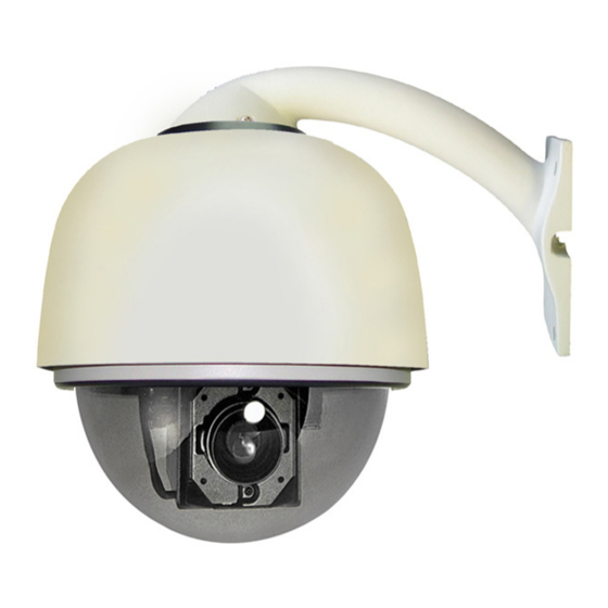
Page 1: User Manual
User Manual Tele DM 567 / DM 569 High Speed Dome Before attempting to intall or operate on this product, please read this manual carefully and keep it for future use. -
Page 2: Table Of Contents
TABLE OF CONTENTS I. Notice -------------------------------------------------------------------------------------------2 II. Installation Instruction of the Acrylic Dome Shield-------------------------------------4 III. Install Bend-Tube-Style Bracket ----------------------------------------------------------5 IV. Description of Wiring -----------------------------------------------------------------------6 V. Function Description ------------------------------------------------------------------------6 VI. Function Setting -----------------------------------------------------------------------------8 VII. General Failure Analysis Table ---------------------------------------------------------12 VIII. Main Technial Indexes ------------------------------------------------------------------13... -
Page 3: Notice
Notice: Signal Communications Limited reserves the right to make improvements to the product described in this manual at any time and without prior notice. This manual is copyrighted. All rights are reserved. This manual may not be copied, reproduced or translated in whole or part without prior consent from Signal Communications Limited. - Page 4 1. Before installing the full-view High-Speed Dome Video Camera, please read this user’s manual first. 2. This unit should be operated only from the type of power source indicated on the marking label found at the power adapter. If you are not sure of the type of power supply you plan to use, consult your appliance dealer or local power company.
-
Page 5: Installation Instruction Of The Acrylic Dome Shield
II. Installation Instruction of the Acrylic Dome Shield Remove Acrylic DOME shield (Please do not scrape the Acrylic shield. It is recommended to wear cotton gloves when operate). As shown in the figure below, first take the flexible flat cable through connector above the base plate and buckle it on the connector. -
Page 6: Install Bend-Tube-Style Bracket
III. Install Bend-Tube-Style Bracket Fig 3.1 Connecting the dome to the wall mount with the bracket. Fig 3.1 Wall mount bracket installation... -
Page 7: Description Of Wiring
IV. Description of Wiring Figure 4.1 Color code of wiring V. Function Description High-Speed Dome Video Camera is an all-in-one high-tech monitoring product, which integrates high-definition color video camera, universal gear change pan-tilt and multi-function decoder. This product furthest reduces the tedious processes of connection and installation between system parts and thus increases system reliability. - Page 8 3. Intelligent Nonvolatile (power-off) memory operation Provides more than 50 preset points (including pan-tilt position and preset focal length) and saved in the nonvolatile memory. Support Dome device to scan between two points horizontally and the scanning speed can be adjusted.
-
Page 9: Function Setting
VI. Dome Setting 1. Before installing the dome device, set the dip-switches to match the communication protocol, transmission baud rate, and dome address ID of the control device. Figure 6.1 Location of the ID number dip-switch and Protocol/Baud rate dip-switch. 2. - Page 10 Figure 6.2 Setting of Dome Device ID [“O” represents ON] switch state Dome Address (ID Number) … … … … … … … … …...
- Page 12 2) Press DWELL. 3) Input a preset number which you want to be your home position. 4) Press PRESET. Delete Home Position 0 + DWELL + 0 + PRESET Set Preset Tour Sequence TOUR(hold 2 sec) + S + Enter + N + Enter(+N+Enter+N+Enter+… )+ 1) Press and hold TOUR for 2 seconds.
-
Page 13: General Failure Analysis Table
VII. General Failure Analysis Table Fig 7.1 Troubleshooting List Problem Possible Reason Troubleshooting Description After power on, no Power supply module is Change motion and no image. damaged or power is not enough. Power cable is connected Correct improperly. Failure occurs on Eliminate engineering line. -
Page 14: Main Technial Indexes
VIII. Main Technical Indexes Power AC24V 2A Weight 3.5Kg Installation Specification Wall, Pendant, Pole, Corner Mount Method Operating ~ 50 (normal range) ℃ ℃ Temperature ~ 2 40° /s Horizontal 6 0° /s Basic Vertical ~ Function of Preset position Dome Scanning tracks (depending on different protocols)
Need help?
Do you have a question about the DM 567 and is the answer not in the manual?
Questions and answers