
Related Manuals for TeleEye DM720 Series


Summary of Contents for TeleEye DM720 Series
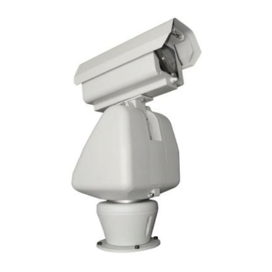
- Page 1 DM720 Integrated Positioning Camera Ⅰ Before using the product, please read this manual carefully.
- Page 2 Declaration This equipment has been tested and founded to comply with the limits for a Class A digital device, pursuant to part 15 of FCC rules and European Union 89/336/EEC directive and its latest amended version. These limits are designed to provide reasonable protection against harmful interference when the equipment is operated in a commercial environment.
-
Page 3: Table Of Contents
CONTENTS 1. Introduction ............................... 1 2.Installation ..............................2 2.1. Installation Type Guide ............................2 2.2. Installation Tools ..............................3 2.3. Wall Mount ................................4 2.4. Corner Mount ............................... 5 2.5. Pole Mount ................................6 2.6. Pedestal Mount ..............................7 2.7. Connections ................................. 8 3. - Page 4 7. Pan/Tilt Function ............................. 21 7.1. Pan/Tilt Parameters .............................. 21 7.2. Water Jet Setup ..............................22 7.3. Wiper ................................... 22 7.4. Defroster Setup ..............................22 7.5. Pan Setting ................................22 7.6. Motion Detection ..............................22 8. Function Setting ............................24 8.1.
-
Page 5: Introduction
& tilt move stably and accurately without vibration even in magnifying zoom position. With the heater, fan, sun shroud, defroster and wiper, TeleEye DM720 can be applied to atrocious outdoor environment, such as airport, frontier, seaport, customs etc. 360° pan and -90° ~ 40° tilt will provide you wide view and image capture and multi protocol options can make it integrate to your existing system easily. -
Page 6: Installation
2.Installation INSTALLATION TYPE GUIDE INSTALLATON TYPE GUIDE 2.1. Installation Type Guide Four main kinds of installation are available for integrated positioning system: 1) Wall Mount 2) Corner Mount 3) Pole Mount 4) Pedestal Mount NOTE: Installation site should be able to bear at least 4 times the weight of the positioning system. 1. -
Page 7: Installation Tools
2.2. Installation Tools Common installation tools are listed in following pictures: D rill s leeve for M8 screw Inner hexagon wrench for M8 screw Cross head screw driver Shift wrench... -
Page 8: Wall Mount
2.3. Wall Mount Setup Conditions It is suited for installing on hard wall, indoor or outdoor: 140.0 ⑴ Wall thickness: be enough to install M8 (100mm length or above) expansion bolt ⑵ Bearing load: 4 times the weight of the integrated camera 8 4 . -
Page 9: Corner Mount
2.4. Corner Mount Setup Conditions Corner mount adapter It is suited for installing on hard wall with a 90°corner, indoor or outdoor. 12 0 8-M8 foundation bolt ⑴ Wall thickness: be enough to install M8 (100mm length) 8-M8 nut, spring washer&flat washer expansion bolt. -
Page 10: Pole Mount
2.5. Pole Mount Setup Conditions Pole adapter It is suitable for installing on the solid pole which is indoor or 2 metal clamps outdoor. ⑴ Pole diameter: Ф130-152mm. ⑵ Bearing load: 4 times the weight of the integrated camera assembly. Picture 10 Installation Steps ⑴... -
Page 11: Pedestal Mount
2.6. Pedestal Mount Setup Conditions ⑴ It is highly recommended to use the pole provided by the dealer. ⑵ Bearing load: 4 times the weight of the integrated camera assembly. 4-M8 nut, spring washer&flat Installation Steps washer ⑴ Put the pedestal mount on a solid, aclinic ground, aim the 4 Power cable&video cable holes on bracket adapter to the 4 M8 screws on the flange, route the control cable, power cable and video cable through... -
Page 12: Connections
2.7. Connections Connections for using RS-485 control Power cable (24V) Video cable (75 ohm coaxial cable) Video switching matrix Communication cable Video output Monitor System controller C O M 1 RS485A/B... - Page 13 n Connections for using coaxial control Power cable 24V Power cable 24V video cable Communication cable video cable Communication cable 75 ohm coaxial cable 75 ohm coaxial cable Coaxial convertor Video input Video output Monitor or video matrix Keyboard or control matrix...
-
Page 14: Menu Operation
3. Menu Operation Operation Instruction NOTE: If you want to switch the characters, move the Two methods are available for carrying out the opera- joystick clockwise or anticlockwise and hold it for tion by the system controller. two seconds. Press the combined hot keys to operate different If you want to scroll the next group of selection, functions. - Page 15 Menu Tree System Setup ==================================== 1.Device Information 2.Display Configuration 3.Change Password 4.Language Select 5.Factory Default 6.System Restart 7.About 8.Back 0.Exit Lens Parameters ==================================== 1.Zooming Speed :High/low 2.Max Digital Zoom :Off 3.Focus Limit :30cm 4.Vibration Correction: Off 5.Iris ALC Value :106 6.Iris PLC Value :016 7.Auto Recovery...
-
Page 16: System Setup
4. System Setup NOTE: Main menu à System Setup 1. If the S/N is not identical with the original one, System Setup ==================================== the following picture will pop up. Please repeat step 1.Device Information 2.Display Configuration 1 to step 5. 3.Change Password 4.Language Select 5.Factory Default... -
Page 17: Display Configuration
1. Title Display Edit System Title This allows you to program how titles are displayed ------------------------------- INPUT :0000000000 on the monitor. The following titles can be set: BACK System Title (ON,OFF, 2s-60s): Displays the ------------------------------- system title. Uppercase Zoom Shift Presets Title (ON, OFF, 2s-60s): Displays preset title when calling up the preset. -
Page 18: Change Password
Information Text Position Enter New Password ==================================== Input [******] System Title Back Preset/Pattern/ Autoscan Title Region Title 7. Confirm the new password. It is necessary to en- 16:25:06 134/074 Time/Date ter the new password again. 05-01-00 Zoom times Confirm Password Vertical tilt degree ==================================== Horizontal pan degree... -
Page 19: Language Select
4.4. Language Select Zooming Speed HIGH User Defined R Max Digital Zoom User Defined B Main menu à System Setupà Language Select Focus Min Limit 30CM Backlight Mode Iris ALC value Backlight Value Language Select Iris PLC value Auto Stop Timer ==================================== 1.Language: English... - Page 20 Move the joystick to select ABOUT, the following pic- ture will be displayed on the screen. Camera S/N :0000000000000000 Camera ID :0001<SOFT> Baud Rate :4800bps Protocol :FACTORY Model :DM729 Camera temp :+25C/+77F Version :2.01(091105) Copy right :2003, 2005 Any Command to Exit NOTE: The menu screen will be closed automatically as any command is carried out.
-
Page 21: Lens Parameters
5. Lens Parameters Main menu àLens Parameters 5.5. Iris ALC Value Lens Parameters ==================================== 1.Zooming Speed :High/low (Some camera only) 2.Max Digital Zoom :Off 3.Focus Limit :30cm Iris average level control value is set here. The value 4.Vibration Correction: Off 5.Iris ALC Value :106 6.Iris PLC Value... -
Page 22: Color/Mono Mode
5.8. Color/Mono Mode Day/Night Mode ==================================== 1.Color/Monot Mode : AUTO 2.Color Start Time : 00:00 3.Mono Start Time : 00:00 4.Back 0.Exit The Color/Mono mode automatically switches be- tween color and monochrome mode in accordance with the environment illumination. Four settings are available: Setting Description... -
Page 23: Camera Parameters
6. Camera Parameters Main menu à Camera Parameters Mode Shutter Iris Camera Parameters ==================================== Auto 1.Picture Freeze :OFF 1/1.5、 2.Exposure Mode 3.White Balance 1/3、 4.Backlight Mode 1/6、 5.CCD Drive Mode :Progress 1/12、 6.Back 0.Exit 1/25、 1/50、 1/100、 6.1. Picture Freeze Shutter 1/150、... -
Page 24: Backlight Mode
User Defined R: The value for the red setting As the backlight mode is set in the standard WDR increases, the image appears redder. mode, WDR2 function can be selected as OFF or User Defined B:The value for the blue setting ON, otherwise it will be invalid, and it is the addi- increases, the image appears bluer. -
Page 25: Pan/Tilt Function
7. Pan/Tilt Function Enable the function (default setting) Main menuà Pan/Tilt Parameters OFF: Disable the function Pan/Tilt Function ==================================== 1.Pan/Tilt Parameters Set North Direction 2.Water Jet Setup 3.Wiper 4.Defroster Setup User can set the camera’s orientation on screen by us- 5.Pan Setting 6.Motion Dection ing joystick to position north. -
Page 26: Water Jet Setup
Vertical: 13~130 Jet Dwell Time (000-255): Dwell time for jetting. 000 means OFF, 001 means 1second. 130° Return to Origin (ON/OFF): Return the camera back to the original place after jetting. 90° Enable the function OFF: Disable the function Run: Run the jetting function by choosing it in this menu. 7.3. - Page 27 Motion Detection ==================================== 1.Motion Detect Mode :OFF 2.Sensitivity Level :003 3.Motion Linkage :OFF 4.Back 0.Exit Motion Detect Mode: You can set it as “ON” or “OFF” to activate or close this function. Move To The Object... Call Preset1 To Confirm Call Preset2 To Cancelt Move your dome to your desired area, call preset 1 to confirm, call preset 2 to cancel your setting.
-
Page 28: Function Setting
8. Function Setting Main menuà Function Setting Call Preset 1 Save Call Preset 2 cancel Function Setting ==================================== 1.Presets Setup 2.Sequence Setup 3.Pattern Setup 4.Autoscan Setup 5.Regions Setup 6.Time Action 7.Idle Action 8.Back Move to the desired position and zoom to a suitable 0.Exit level, call preset 1 to save the current preset, and call 8.1. -
Page 29: Pattern Setup
8.3. Pattern Setup 3. Edit Sequence: Order and pause time spent at each preset position is set here. It is possible to set 32 Main Menuà Function Settingà Pattern setup positions as shown in the following illustration. Pattern Setup [Preset Number -Dwell Timer] ==================================== ==================================== 1.Pattern Number... -
Page 30: Autoscan Setup
8.4. Autoscan Setup Move to start point Call preset 1 to confirm Call preset 2 to cancel Main menuà Function Settingà Autoscan setup Autoscan Setup ==================================== 1.Autoscan Number :001 2.Title 3.Set Left Limit 4.Set Right Limit Move the joystick to record the zoom operation. 5.Defaul Speed :255 6.Run Continuously... -
Page 31: Regions Setup
Up to four regions can be set. 4. Set Right Limit: The right edge of the area to be scanned is set here. 1. Region Number: Region number ranging from 001 to 004 is set here. Move to right limit Call preset 1 to confirm Call preset 2 to cancel 2. -
Page 32: Time Action
NOTE: 5. Delete Current: The current region is deleted. The The specified time can not be overlapped. Otherwise, following picture is displayed on the screen. the assigned Timer Running functions are ineffective. Timer Running function is prior to Auto Action function. -
Page 33: Privacy Masking
9. Privacy Masking NOTE: Main menuà Privacy Making User should select other place or delete other mask position to set a new one, if the total of mask number Privacy Masking ==================================== exceeds a maximum of eight. 1.Mask Number :001 2.Setup New Mask User should set new mask position, if the setting 3.Activate... -
Page 34: Appendix I: Dip Switch & Jumper Settings
1. Remove the plug from the left cover. It is not neces- either ON or OFF. Default setting is factory. sary to remove the pan and tilt cover. 2. Set the baud rate and receiver address. Switch Number 3. Replace the plug. Protocol TeleEye DM2 ○ PELCO_P ○ ○ PELCO_D PELCO_C* ○... - Page 35 System address setting Address setting chart The control commands contain target system’s ID. The O means ON, blank means OFF. system only reacts to the command sent to its own ad- Switc h Numb e r dress or broadcast address. So, each system should be assigned an address.
- Page 36 Sw itc h N u m b e r Sw itc h N u m b e r -32-...
- Page 37 Sw itc h N u m b e r Sw itc h N u m b e r 1 3 2 1 7 6 1 3 3 1 7 7 1 3 4 1 7 8 1 3 5 1 7 9 1 3 6 1 8 0 1 3 7...
- Page 38 Switc h Num b e r Pro g ra m- ma b le Ad d re ss -34-...
-
Page 39: Appendix Ii: Rs485 Bus Basic Knowledge
Appendix II: RS485 Bus Basic Knowledge Characteristics of RS485 Bus 3-2 The connection of 120 Ohm termination resistor: As specified by RS485 standards, RS485 Bus is of The termination resistor is ready on the Protocol half-duplexed data transmission cables with char- PCB. - Page 40 4. Problems in practical connection In some circumstances user adopts a star configu- In such circumstances the factory recommends the ration in practical connection. The termination re- usage of RS485 distributor. The distributor can change sistors must be connected to the two equipment the star configuration connection to the mode of con- that are farthest away from each other, such as nection stipulated in the RS485 standards.
-
Page 41: Appendix Iii: Lightning Proof & Surge Proof
Appendix III: Lightning Proof & Surge Proof The system must be grounded with equal potentials. The product adopts TVS lightning proof technology to The earth ground connection must satisfy the anti-in- prevent from damage by lightning strike below 4000V and impulse signals such as surge; but it is also neces- terference and electrical safety requirements and must not short circuited with high voltage electricity net. -
Page 42: Appendix Iv: Trouble Shooting
Appendix IV: Trouble Shooting Possible Causes Trouble Solutions 1. The AC power sup ply is not connect to the port of the connection board or the 1. Check the connection of the power supply to ensure the contact is not good. socket is in good condition The red LED 2. -
Page 43: Appendix V: Technical Specification
Appendix V: Technical Specification 1. Dimension (unit: mm) 2 1 0 34 0 Side Look Dimension Front Look Dimension Overlook Dimension 2. General 9 language OSD menu ( English, French, German, Spanish, Portuguese, Italian, Polish, Russian, Chinese) 220 presets with title 4 tours with up to 32 presets each 4 patterns with PTZ routine, recording time is no less than 180 seconds 4 auto pannings... - Page 44 Range: 0º - 90º Manual speed: 0.1º - 160º/sec Preset speed: 360º/sec Control 220 Presets, 4 Pattern, 4 Tours, 4 Auto Pan Protocol TeleEye DM2, Pelco D, Pelco P POWER / ENVIRONMENT Weather Proof Standard IP66 Continuous Heater Auto Start Operating Temperature -40ºC - 60ºC...
Need help?
Do you have a question about the DM720 Series and is the answer not in the manual?
Questions and answers