
Related Manuals for TeleEye DM870


Summary of Contents for TeleEye DM870
- Page 1 DM870/DM880 High Speed Dome Ⅰ Before using the product, please read this manual carefully.
-
Page 2: Table Of Contents
Index Welcome ............................. 1 Declaration............................2 Installation Preparation .......................... 3 Installaton Type Guide ........................... 4 In-Ceiling Mount ..........................5 Wall Mount ............................8 Corner Mount ............................. 11 Pole Mount ............................14 Pendent Mount ........................... 17 Parapet Mount ........................... 20 Operation ............................23 A. -
Page 3: Welcome
Welcome Thank you for purchasing our HIGH SPEED DOME. This series speed dome is newly upgraded with AMP connector for easier installation and black liner for discreet surveillance. The powerful functions make it a state-of-the-art speed dome, and it will fulfill your wide range profes- sional security surveillance need. -
Page 4: Declaration
Declaration This equipment has been tested and found to comply with the limits for a Class A digital device, pursuant to part 15 of FCC rules and European Union 89/336/EEC directive and its latest amended version. These limits are designed to provide reasonable protection against harmful interference when the equipment is operated in a commercial environment. -
Page 5: Installation Preparation
Installation Preparation Tools Lists: Wiring Diagram for alarm, video You may need following tools for the installation: &RS485 and Power Screws and nuts, screw driver, Small slotted screw driver, Wire cutter, Ladder, Drill, Saw. Cables: Video Coaxial Cable The video coaxial cable should be: 1) 75 Ohm impedance. -
Page 6: Installaton Type Guide
Installation Type Guide INSTALLATION TYPE GUIDE INSTALLATON TYPE GUIDE Two main kinds of installation are available for high speed Type Weight (kg/lb) dome: Indoor Ceiling Dome 2.43kg (5.35lb) 1) In-ceiling Mount Outdoor Dome 2) Bracket Mount 3.78kg (8.33lb) (excluding bracket) There are 5 bracket options for bracket mount: Pendant Bracket 1.53kg (3.37lb) -
Page 7: In-Ceiling Mount
In-Ceiling Mount Installation requirements: 1. The thickness of the ceiling should be less than 42mm. 2. The ceiling should be able to bear 4 times the weight of the speed dome. 3. Upper space should be at least 20cm high. 1 Draw a circle on ceiling Take the paper pattern(accessory) as a template to draw a pattern on the ceiling. - Page 8 Water proof Conne cto r 4 Prepare cables Prepare wiring and then put Power/RS485/Video cables through water-proof connector and the top of housing. Finally, turn the connector into the top hole of the housing. 5 Connect cables Alarm Insert cables into corresponding sockets on power Red LED board.
- Page 9 SPONGE 8 Set dome ID, baud rate and protocol Set dome ID, baud rate and protocol via DIP switches (please refer to APPENDIX I ). Remove the two SPONGE sponges. Install black liner and Pan/Tilt Module Guide Pole AMP Socket Push the black liner into the two locking tabs.
-
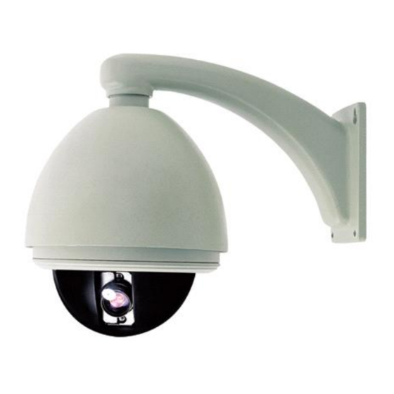
Page 10: Wall Mount
Wall Mount Installation requirements: The wall mounting surface must be firm enough to bear 4 times the weight of the speed dome. Mark screws positions Take the bracket base as the template to mark the screws positions on wall. Drill the holes and put ex- pansion screws inside. - Page 11 Unfasten the power board holder Loosen the bolt and swing away the power board holder. Bolt Install housing Insert cables through the hole at the top of the housing Apply water-proof tape to the housing thread. Then turn the housing onto the wall mount bracket and retain the connection with an M4 screw.
- Page 12 Connect the two Down cover preliminary installation ports of the heater Attach the safety chain with an M3 nut as picture shows. The safety chain prevents the down cover M3 Nut from dropping down. Safety Chain NOTE: Connect the heater plug into the socket in the case of outdoor dome.
-
Page 13: Corner Mount
Corner Mount Installation requirements: The corner mounting surface must be firm enough to bear 4 times the weight of the speed dome. Mark screws positions Take the bracket base as the template to mark the screws positions on wall. Drill the holes and put expansion screws inside. - Page 14 Install bracket Put cables through the cavity of bracket and fasten bracket on base. Unfasten the power board holder Loosen the bolt and swing away the power board holder. Bolt Install housing Insert cables through the hole at the top of the hous- ing Apply water-proof tape to the housing thread.
- Page 15 SPONGE 7 Set dome ID, baud rate and protocol Set dome ID, baud rate and protocol via DIP switches SPONGE (please refer to APPENDIX I ). Remove the two sponges . Down cover preliminary installation Attach the safety chain with an M3 screw as Connect the two ports of the heater picture shows.
-
Page 16: Pole Mount
Pole Mount Installation requirements: The outside diameter of the pole must be in the range of 130-150mm (5.12 ~6 inches). Install base Mount the pole adaptor to the pole with two mount- ing clamps. Put Power/RS485/Video cables through the central hole of the bracket base, and then fix it around the pole. - Page 17 3 Unfasten the power board holder Loosen the bolt and swing away the power board holder. Bolt Install housing Insert cables through the hole at the top of the hous- ing Apply water-proof tape to the housing thread. Then turn the housing onto the wall mount bracket and retain the connection with an M4 screw.
- Page 18 Down cover preliminary installation Connect the two ports of the heater Attach the safety chain with an M3 nut as picture shows. The safety chain prevents the down cover from dropping down. M3 Nut Safety Chain NOTE:Connect the heater plug into the socket in the case of outdoor dome.
-
Page 19: Pendent Mount
Pendent Mount Installation requirements: The ceiling must be firm enough to bear 4 times the weight of the speed dome. Mark screws positions Take the bracket base as the template to mark the screws positions on ceiling. Drill the holes and put expansion screws inside. - Page 20 3 Install suspender Put cables through the cavity of suspender. Apply water-proof tape to the thread. Then turn the thread pipe head into the bracket base and fasten the connection with an M4 screw. NOTE: Apply silicone to the suspender as picture shows in the case of outdoor dome.
- Page 21 SPONGE Set dome ID, baud rate and protocol Set dome ID, baud rate and protocol via DIP switches SPONGE (please refer to APPENDIX I ). Remove the two sponges. Connect the two Down cover preliminary installation ports of the heater Attach the safety chain with an M3 nut as picture shows.
-
Page 22: Parapet Mount
Parapet Mount Installation Requirements: Bracket Base The wall mounting surface must be firm enough to bear 4 times the weight of the speed dome. Mark Screws Positions Take the bracket base as the template to mark the screws positions on wall, drill the holes. Install Base Fix the bracket base on the wall with the M8 expan- sive screws. - Page 23 4 Unfasten the power board holder Loosen the bolt and swing away the power board holder. 5 Install the Housing Bolt Insert cables through the hole at the top of the hous- ing Apply water-proof tape to the housing thread. Then turn the housing onto the wall mount bracket and retain the connection with an M4 screw.
- Page 24 Connect the two Down cover preliminary installation. ports of the heater Attach the safety chain with an M3 nut as picture shows. The safety chain prevents the down cover M3 Nut Safety Chain from dropping down. NOTE: Connect the heater plug into the socket in the case of outdoor dome.
-
Page 25: Operation
Operation A. Operation Instruction Accessing to System Menu Access the dome’s main system menu on your Two methods are available for carrying out the opera- monitor by calling preset 95 once or calling preset tion by the system controller. 1 twice within 5 seconds. Press the combined hot keys to operate different Note: The way to call a preset may vary among key- functions. -
Page 26: Menu Tree
B. Menu Tree System Information ==================================== Page 26 1.Dome Information 2.Disp Information 3.Init Information 4.Change Password 5.Language Select 6.Factory Default 7.Restart 0.Back Lens Parameters ==================================== Page 30 1.Zoom Speed :High 2.Digital Zoom :Off 3.Joystick Auto :Both 4.Auto Focus 5.Auto Iris 6.Iris ALC :084 7.Iris PLC... -
Page 27: Menu Operation
C. Menu Operation Main menu àSystem Informationà Change Password Selecting item Change Password In the main menu, the cursor flashes on the left, ==================================== move the joystick up or down to move the cursor 1.Input Old Pwd : ****** 2.Input New Pwd : ****** to the desired setting item. -
Page 28: System Information
1. System Information Dome Title: It is the title of the dome. System menu à System Information Assigning a name to a dome helps user to remember System Information which dome it is. Please refer to operation on page ==================================== 1.Dome Information 25 to learn how to edit title. -
Page 29: Display Information
1.2 Display Information 1.2.2 Other Information System Menuà System Information à Display Infor- mation Other Information ==================================== 1.Zoom Times Infor :o f f Display Configuration 2.Direction Infor :o f f ==================================== 3.AlarmState Infor :o f f 1.Title Information 4.Dome Clock Infor : off 2.Other Information 0.Back 0.Back... -
Page 30: Factory Default
1.3 Init Information 1.5 Language Select System Menuà System Information à Init Informa- System Menuà System Information à Language Se- lect tion Init Information ==================================== Language Select 1.Dome S/N ==================================== 2.Dome ID Language: English 3.Baudrate 4.Protocol 5.Model 6.Version 7.Fan Speed 8.Temp 0.Back Select one language. - Page 31 1.7 Restart System Menuà System Information à Restart System Information ==================================== 1.Dome Information 2.Disp Information 3.Init Information 4.Change PassWord 5.Language Select 6.Factory Default 7.Restart 0.Back Select Restart to reboot the dome. Then the pop-up win- dow appears as below. Settings will not change after restarting.
-
Page 32: Lens Parameters
2. Lens Parameters 001-255: The dome will start auto focus in the number of seconds that have been set System Menu à Lens Parameters (001 to 255) after user manually adjusts Lens Parameters focus. ==================================== 1.Zoom Speed :High 2.Digital Zoom :Off 3.Joystick Auto :Both... - Page 33 2.7 Iris PLC To set the iris peak level control value. The value could be 000~127. Default value: 23X color/mono camera: 016 (different camera has different PLC default value) Note: Changing default value is strongly NOT recommended. 2.8 Day/Night Mode To set the dome color/monochrome switching mode.
-
Page 34: Camera Parameters
3. Camera Parameters Exposure Mode ==================================== 1.Mode :Shutter System Menu → Camera Parameters 2.Shutter :1/50 3.Iris :N/A 4.AGC :N/A Camera Parameters 0.Back ==================================== 1.Sensitivity Up 2.AE Mode 3.Preset Freez 4.White Balance Lens Parameters 5.BLC Mode ==================================== 6.Video Phase 1.Zoom Speed :High 7.Focus Min Limit 2.Digital Zoom... -
Page 35: White Balance
3.3 Preset Freeze Therefore backlight compensation can increase the brightness of the objects in the center. System Menu → Camera Parameters → Preset Freeze OFF: Disable the function. BLC: Standard BLC mode. Preset Freeze Setup WDR: Wide Dynamic Rage mode. ==================================== Preset Freeze : Off When the backlight mode is setting in the standard... -
Page 36: Pan/Tilt Parameters
4. Pan/Tilt Parameters System Menuà Pan/Tilt Parameters 4.4 North Direction User can set dome’s orientation on screen by us- Pan/Tilt Parameters ing joystick to position north. ==================================== 1.Auto Stop Time :off Pan degree is the relative degree to a specific 2.Speed Adjust 3.Proportion Direction PT direction. -
Page 37: Auto Running Setup
5. Auto Running Setup System Menu à Auto Running Setup Note: If you are not familiar with editing, please refer to Operation on page 25. Auto Running Setup ==================================== Setting Select a preset number then move right. The 1.Preset Setup 2.Sequence following menu will display. -
Page 38: Pattern Setup
5.2 Sequence Select Save to save the sequence, select Back to quit without saving. System Menu à Auto Running àSequence Setup Note: When a preset’s dwell time is set 0, system will skip that preset. System will consider pre- Sequence ==================================== 1.Number :001... - Page 39 Note: Dome makes horizontal movement only. Call Preset 1 Start Call Preset 2 Cancel Tips: Zoom to desired level then run panning, the camera will keep that zoom. Number: Display the current panning number. Val- ues are 001~004. Pan right then tilt up or Move and zoom the camera in any route and speed you down to select other panning.
-
Page 40: Region Setup
5.5 Region Setup 5.6 Idle Time Setup This function let the system automatically run assigned System Menu à Auto Running Setup à Region Setup function after the idle time. For example: the dome is Region Setup running a sequence and an operator breaks the se- ==================================== 1.Number :001... -
Page 41: Timer Running Setup
6.Timer Running Setup System Menuà Timer Running Setup Timer Running Setup ==================================== Schedule Start Running 00:00 00:00 00:00 00:00 00:00 00:00 00:00 00:00 00:00 00:00 00:00 00:00 00:00 00:00 00:00 00:00 0.Back This function allows the system to run specified func- tions during the scheduled time. -
Page 42: Privacy Masking
7. Privacy Masking 2. Set position Note: Privacy masking is for some models only. Enter setting, the following window will pop up: System Menu à Privacy Masking Privacy Masking Call Preset 1 :Size ==================================== Call Preset 2 :Cancel... 1.Mask No 2.Setting 3.Activate Empty... - Page 43 Method B The setting has two steps: 1. Choose area, 2. Set size. 1. Choose area Call Preset 1 :Size Call Preset 2 :Cancel... ↑↓→← Move Dome Move the cross to the center of desired position, call preset 1 to save the position then go to step 2 or call preset 2 to cancel.
-
Page 44: Alarm Setup
8. Alarm Setup System Menu à Alarm Setup Tips: A symbol will flash when an alarm comes Alarm Setup ==================================== 1.Alarm Input 2.Alarm Mode :manual 3.Set Alarm :Armoff 4.Input State 5.Run Function :off 6.Alarm Output :off 7.Reset Delay 8.Arm Time :00:00 9.DisArm Time :00:00... -
Page 45: Appendix I: Dip Switch & Jumper Settings
○ ○ PELCO_D ○ ○ PELCO_P/4800 ○ ○ PELCO_P/9600 ○ ○ ○ TeleEye DM2 2400 BPS ○ 4800 BPS ○ 9600 BPS SW 2 S W 1 ○ ○ 19200 BPS Protocol and Baud rate setting SW2 is used to set protocol and baud rate.The first six (1-6) bits of SW2 are for protocol setting and the last two (7-8) bits are for baud rate setting. - Page 46 Address setting chart Dome address setting The control commands contain target dome’s ID. The O means ON, blank means OFF. dome only reacts to the command sent to its own ad- Switch Number dress or broadcast address. So, each dome should be assigned an address.
- Page 47 Sw itc h N u m b e r Sw itc h N u m b e r -45-...
- Page 48 Sw itc h N u m b e r Sw itc h N u m b e r 1 3 2 1 7 6 1 3 3 1 7 7 1 3 4 1 7 8 1 3 5 1 7 9 1 3 6 1 8 0 1 3 7...
- Page 49 Video cable type setting Switch Number Speed dome supports two common types of cables to transmit video signal, coaxial cable and twisted pair. Com- paring to twisted pair, coaxial cable does not need extra adaptor and bandwidth is higher but coaxial cable is more expensive and transmission distance is shorter.
- Page 50 Alarm output method setting Resistor jumper setting There are two alarm output methods: NO and NC. NO RS485 bus needs two 120 Ohm resistors at both ends. means normal state is open circuit, the circuit will be Set on the 120 Ohm resistors of the two devices (keyboard or dome) in the farthest distance on RS485 closed when an alarm comes in.
-
Page 51: Appendix Ii: Wire Diameter & Transmission Distance Comparison Chart
Appendix II: Wire Diameter & Transmis- sion Distance Comparison Chart The transmission distance listed below are farthest ones recommended for each given wire diameter when the 24V AC voltage loss ratio is below 10% (for equipment powered by AC, the allowed maximum voltage loss ratio is 10%).For example, a set of equipment with nominal power as 80VA, installed 35 feet (10m) away from transformer, needs a wire with a minimum diameter of 0.8000mm. -
Page 52: Appendix Iii: Rs485 Bus Basic Knowledge
Appendix III: RS485 Bus Basic Knowledge Characteristics of RS485 Bus 3-2 The connection of 120 Ohm termination resistor: As specified by RS485 standards, RS485 Bus is of The termination resistor is ready on the Protocol half-duplexed data transmission cables with char- PCB. - Page 53 4. Problems in practical connection In such circumstances the factory recommends the In some circumstances user adopts a star configu- usage of RS485 distributor. The distributor can change ration in practical connection. The termination re- the star configuration connection to the mode of con- sistors must be connected to the two equipment nection stipulated in the RS485 standards.
-
Page 54: Appendix Iv: Lightning Proof & Surge Proof
Appendix IV: Lightning Proof & Surge Proof The product adopts TVS lightning proof technology to The system must be grounded with equal potentials. prevent from damage by lightning strike below 4000V The earth ground connection must satisfy the anti- and impulse signals such as surge; but it is also neces- interference and electrical safety requirements and sary to abide by the following precautions to ensure elec- must not short circuited with high voltage electricity... -
Page 55: Appendix Vi: Trouble Shooting
Appendix VI: Trouble Shooting Trouble Possible Causes Solution If the red LED on the power board in the housing is not lit, causes may be: 1. The 24V AC power supply is not connected to 1. Check if the power supply is connected, or the port of the power board or the contact confirm if the plug contacts well is not good... -
Page 56: Appendix Vii : Specification
Range: 0º - 90º Tilting Manual speed: 0.1º - 160º/sec Preset speed: 360º/sec 220 Presets, Control 4 Pattern, 4 Tours Protocol TeleEye DM2, Pelco D, Pelco P Built-in Alarm 7 Inputs, 2 Outputs POWER / ENVIRONMENT Weather Proof Standard IP66 Continuous Heater... - Page 57 DM880 Specifications Model DM882 DM889 CAMERA OPTICS PAL (625 lines, 50 fields per second) Scanning System NTSC (525 lines, 60 fields per second) Image Sensor 1/4" interline transfer CCD 480 TVL (Day) Resolution 550 TVL (Night) Minimum Illumination 0.1 Lux at 1/4 sec F1.6, 50IRE (ICR-on) Electronic Sensitivity Boost On / Off Video Output Level...
Need help?
Do you have a question about the DM870 and is the answer not in the manual?
Questions and answers