Extron electronics IN1606 Setup Manual
Scaling presentation switcher
Hide thumbs
Also See for IN1606:
- User manual (85 pages) ,
- User manual (132 pages) ,
- User manual (95 pages)
Table of Contents
Advertisement
Quick Links
Download this manual
See also:
User Manual
IN1606 • Setup Guide
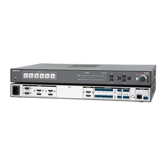
The Extron IN1606 Scaling Presentation Switcher is a six input, HDCP-compliant video scaler that accepts a wide variety of audio and video
formats. This guide allows an experienced user to set up and configure the IN1606. It covers how to perform basic operations using the front panel
controls and selected Simple Instruction Set (SIS™) commands.
NOTE:
For full installation, configuration, menus, connector wiring, and operation details, see the IN1606 and IN1608 Series User Guide, at
www.extron.com.
Installation
Rear Panel Features
a
b
c
INPUTS
100-240V ~ 50/60 Hz
0.5 A MAX
1
3
CONFIGURABLE
2
4
HDMI
Figure 1.
Rear Panel Connectors
Power and Input Connections
a
AC power connector
b
Configurable analog 15-pin HD (VGA) connectors (inputs 1 and 2)
c
HDMI input connectors (inputs 3 through 6)
d
Analog audio input connectors (associated with inputs 1 through 6)
e
Mic/Line audio input connectors and adjacent phantom power LEDs
Mounting and Cabling
Step 1 — Mounting
a.
Turn off or disconnect all equipment power sources.
b.
Mount the IN1606 to a rack using the pre-installed rack ears (see figure 2) or remove the
rack ears and use an optional mounting kit for under-the-desk mounting (see figure 3).
Step 2 — Connecting inputs
a.
Connect analog video sources to the 15-pin HD connectors (see
b.
Connect digital HDMI or DVI (with an appropriate adapter) sources to the HDMI
connectors (see
c
above).
c.
Connect audio input sources to the 5-pole captive screw connectors (see
d.
Connect Mic/Line input sources to the 3-pole captive screw connectors (see
Step 3 — Connecting outputs
a.
Connect suitable video displays to the HDMI connectors (see
b.
Connect audio output devices to the 5-pole captive screw connectors (see
ATTENTION:
For unbalanced outputs, do not connect wires to the "-" poles
(see the IN1606 and IN1608 Series User Guide for wiring details).
Step 4 — Connecting control devices
a.
For control through Ethernet, connect a LAN or WAN to the RJ-45 connector
(see
h
above). The default IP address is 192.168.254.254. The default subnet mask is
255.255.0.0.
b.
For serial RS-232 control, connect a host device to the 3-pole captive screw connector
i
(see
above). The default baud rate is 9600.
c.
For control through USB, connect a host device to the front panel mini USB B port.
(see
a
on page 2).
Step 5 — Connecting power
Connect a 100 to 240 VAC, 50-60 Hz power source to the power AC power connector (see
IN1606
5
6
HDMI
f
d
e g
OUTPUTS
AUDIO INPUTS
OUTPUTS
A
1
1
L
1
R
L
3
R
L
5
R
MIC/LINE
B
+48V
VARIABLE
HDMI
L
2
R
L
4
R
L
6
R
2
L
+48V
Output Connections
f
HDMI output connectors
g
Analog audio output connectors
b
above).
d
above).
e
above).
f
above).
g
above).
Mounting Screws
(2) Places
Each Side
#8 Screw
(4) Places
Each Side
a
above).
h i
REMOTE
2
LAN
RS-232
R
RESET
Tx Rx
G
Control Connections
h
LAN connector
i
RS-232 connector
Rack Ears
Rack Mount
Figure 2.
MBU 149
Mounting Bracket
Furniture Mount
Figure 3.
1
Advertisement
Table of Contents

Related Manuals for Extron electronics IN1606


Summary of Contents for Extron electronics IN1606
-
Page 1: Rear Panel Features
The Extron IN1606 Scaling Presentation Switcher is a six input, HDCP-compliant video scaler that accepts a wide variety of audio and video formats. This guide allows an experienced user to set up and configure the IN1606. It covers how to perform basic operations using the front panel controls and selected Simple Instruction Set (SIS™) commands. -
Page 2: Front Panel Overview
Executive mode 1 — The front panel is completely locked. This can only be enabled or disabled using SIS commands or the internal web pages (see the IN1606 and IN1608 Series User Guide for web page details or the rear page of this guide for the SIS command). -
Page 3: Firmware Upgrades
, where is the SIS value for the resolution and refresh rate combination as given in the example table below (see the IN1606 and IN1608 Series User Guide for the full list). SIS Variable for EDID or Output Resolution and Refresh Rate Combination (Where... - Page 4 View the current variable volume level. D8GRPM NOTE: By default, setting the audio mute with the following commands affects all outputs (see the IN1606 and IN1608 Series User guide to configure the master audio mute through group masters). Set master audio mute Enable or disable master audio mute.
Need help?
Do you have a question about the IN1606 and is the answer not in the manual?
Questions and answers