Extron electronics IN1804 Series Setup Manual
Hide thumbs
Also See for IN1804 Series:
- User manual (110 pages) ,
- User manual (113 pages) ,
- Setup manual (4 pages)
Advertisement
Quick Links
IN1804 Series • Setup Guide
The Extron IN1804 Series Scaling Presentation Switchers are four input, HDCP-compliant AV scalers that accept a wide variety of
audio and video formats and provide HDMI and DTP/DTP2/XTP/XTP2/HDBaseT video outputs. This guide provides instructions
for an experienced user to set up and configure IN1804, IN1804 DI, and IN1804 DO scalers. It covers how to perform basic
operations using the front panel controls and selected Simple Instruction Set (SIS™) commands.
NOTE:
For full installation, configuration, menus, connector wiring, and operation details, see the IN1804 Series User Guide
at www.extron.com. For information on configuration using the Extron Product Configuration Software (PCS), see the
IN1804 Series Help file within the software.
Installation
Rear Panel Features
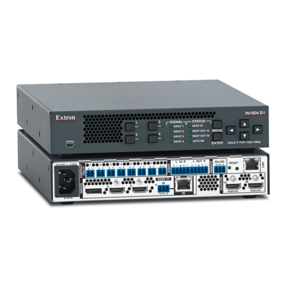
The IN1804 DI and the IN1804 DO are shown below. The rear panel of the standard IN1804 model is similar, except that it does
not have an RJ-45 TP input, RJ-45 TP output connector, or captive screw Over TP IR connector.
IN1804 DI
100-240V~1.0A MAX
1
2
C T
C T
1
50-60 Hz
B
A
IN1804 DO
100-240V~1.0A MAX
1
2
C T
C T
1
50-60 Hz
A
B
Figure 1.
Rear Panel Connectors, IN1804 DI and IN1804 DO
Mounting and Cabling
Step 1 — Mount the device
a.
Turn off or disconnect all equipment power.
b.
Mount the scaler on top of a flat surface using the provided rubber feet, under a table using an optional mounting kit for
under-desk mounting, or to a rack shelf using an optional rack shelf-mounting kit (kits are available at www.extron.com).
Step 2 — Connect inputs
a.
Connect a DP source to the Input 1 DisplayPort connector (see figure 1,
b.
Connect HDMI or DVI (with an appropriate adapter) video sources to HDMI input 2, input 3, and input 4 (available on IN1804
standard and DO models only) connectors (
For information on safety guidelines, regulatory compliances, EMI/EMF compatibility, accessibility, and related topics, see the
Extron Safety and Regulatory Compliance Guide
N
L
O
M
L
3
4
5
6
7
C T
C T
C T
C T
C T
G
V+
SIG
OVER TP
IR
2
3
4
Tx Rx G
C
D
O
N
M
L
3
4
5
6
7
L
C T
C T
C T
C T
C T
G
V+
2
3
4
c
).
C
on the Extron website.
K
J
I H
G
IN R
L OUT R
RS-232
RESET
Tx Rx G
LINK
1A
1B
IN
HDMI/CEC
HDMI/CEC
E
F
K
J
I H
G
IN R
L OUT R
RS-232
RESET
Tx Rx G
1A
SIG
LINK
OVER TP
IR
1B
OUT
Tx Rx G
HDMI/CEC
P
Q
).
B
A
AC power connector
DisplayPort input connector
B
HDMI input connectors
C
Over TP IR pass-through
D
connector
TP input connector
E
F
HDMI output connectors
LAN connector
G
Reset button
H
I
Reset LED
Remote RS-232 connector
J
Analog audio output
K
L
Analog audio input
+V port (for tally voltage output)
M
Ground pin (for contact/tally
N
ports)
Contact/tally connectors
O
R
TP output connector
P
Q
Over TP IR pass-through
connector
HDMI output connector
R
1
Advertisement

Related Manuals for Extron electronics IN1804 Series


Summary of Contents for Extron electronics IN1804 Series
-
Page 1: Rear Panel Features
IN1804 Series • Setup Guide The Extron IN1804 Series Scaling Presentation Switchers are four input, HDCP-compliant AV scalers that accept a wide variety of audio and video formats and provide HDMI and DTP/DTP2/XTP/XTP2/HDBaseT video outputs. This guide provides instructions for an experienced user to set up and configure IN1804, IN1804 DI, and IN1804 DO scalers. It covers how to perform basic operations using the front panel controls and selected Simple Instruction Set (SIS™) commands. - Page 2 Use Extron XTP DTP 24 SF/UTP cable for the best performance. At a minimum, Extron recommends 24 AWG, solid conductor, STP cable with a minimum bandwidth of 400 MHz. • Terminate cables with shielded connectors to the TIA/EIA-T568B standard (see the IN1804 Series User Guide for more information). •...
-
Page 3: Audio Wiring
To transmit and receive IR signals between DTP or HDBaseT-compatible devices, connect a control device to the Over TP IR 3-pole captive screw connector. NOTE: RS-232 data can be inserted via Ethernet (see the IN1804 Series User Guide or the IN1804 PCS Help File for details). Audio Wiring Wire the audio input and output connectors as shown No Ground Here at right. -
Page 4: Firmware Updates
Download firmware updates from the Extron website and upload them via the internal web pages, PCS, or the Extron Firmware Loader program. © www.extron.com 2018 Extron Electronics All rights reserved. All trademarks mentioned are the property of their respective owners. 68-3274-50 Rev. A 08 18...
Need help?
Do you have a question about the IN1804 Series and is the answer not in the manual?
Questions and answers