Table of Contents
Advertisement
Quick Links
Advertisement
Table of Contents

Related Manuals for Extron electronics IN1508


Summary of Contents for Extron electronics IN1508
- Page 1 IN1508 Scaling Presentation Switcher 68-791-01 Rev. G 03 08...
- Page 2 Precautions Safety Instructions • English This symbol is intended to alert the user of important operating and maintenance (servicing) instructions in the literature provided with the equipment. This symbol is intended to alert the user of the presence of uninsulated dangerous voltage within the product’s enclosure that may present a risk of electric shock.
-
Page 3: Fcc Class A Notice
FCC Class A Notice This equipment has been tested and found to comply with the limits for a Class A digital device, pursuant to part 15 of the FCC Rules. Operation is subject to the following two conditions: (1) this device may not cause harmful interference, and (2) this device must accept any interference received, including interference that may cause undesired operation. -
Page 4: Installation
Ensure that the connected video display is turned on and operating normally so that you can observe the on-screen Y, B-Y, R-Y displays. IN1508 Scaling Presentation Switcher • Quick Start Connect the CAUTION sleeve to ground. Connecting the... -
Page 5: Front Panel Controls
Menu button activates the menu system, or a submenu, or backs up one level within the menu system. QS-2 IN1508 Scaling Presentation Switcher • Quick Start Quick Start — IN1508 , , , and buttons maneuver through the menu system, move the slider on status bar indicators, and move the box indicators. -
Page 6: Table Of Contents
Selection box control Status indicator bar control Main menu system ... 3-16 ... 3-16 Input submenu Center selection Size selection IN1508 Scaling Presentation Switcher • Table of Contents ... 1-1 ... 1-4 ... 2-2 ... 2-2 ... 2-3 ... 2-5 ... - Page 7 Total Pixels status indicator bar Phase status indicator bar Optimizing the Audio Troubleshooting ... 3-39 General checks ... 3-39 Specific problems ... 3-40 IN1508 Scaling Presentation Switcher • Table of Contents ... 3-17 ... 3-17 ... 3-17 ... 3-18 ... 3-18 ... 3-19 ...
- Page 8 Suggested adapters ... A-4 Cables ... A-4 Bulk cables ... A-4 Precut cables ... A-4 High performance DVI cables IN1508 Scaling Presentation Switcher • Table of Contents ... 4-1 ... 4-2 ... 4-2 ... 4-2 ... 4-3 ... A-1 ... A-5...
- Page 9 Table of Contents, cont’d 68-791-01 Rev. G 03 08 All trademarks mentioned in this manual are the properties of their respective owners. IN1508 Scaling Presentation Switcher • Table of Contents...
-
Page 10: Chapter 1 • Introduction
IN1508 Scaling Presentation Switcher Chapter One Introduction About this Manual About the Switcher Features... -
Page 11: About This Manual
Eight unbalanced stereo or mono audio inputs (five inputs on RCA connectors and three inputs on 3.5 mm mini stereo jacks) The IN1508 scales the video inputs to a variety of standard VGA and HDTV resolutions and any of up to 3 available refresh rates. The switcher outputs RGBHV, RGBS, RGsB, or progressive component (Y, B-Y, R-Y) video on a 15-pin HD (VGA) connector. -
Page 12: Dvi Video
HDTV at a reduced blanking interval. The dual link configuration supports the higher bandwidth demands of displays that do not support reduced blanking. The IN1508 switcher supports a single link of DVI-D video. DVI uses a process called transmission minimized differential signaling (TMDS) for sending graphics data to a compatible monitor. -
Page 13: Standard Dvi Cable
Outputs — Video outputs — The IN1508 outputs scaled video signals as progressive RGBHV, RGBS, RGsB, or component video, from 640 x 480 (VGA) up to 1600 x 1200 (UXGA), to match the optimum or native resolution of virtually any display device, on a 15-pin HD connector. - Page 14 This output can drive any line level compatible audio unit, or a local device such as powered speakers. Video output resolutions — The IN1508 outputs an image scaled up to the following output resolutions: •...
- Page 15 3:2 pulldown. Jaggies and other image artifacts can result if conventional deinterlacing techniques are used on film-source video. The IN1508’s advanced film mode processing recognizes signals that originated from film. The switcher then applies video processing algorithms that optimize the conversion of video that was made with the 3:2 pulldown process.
- Page 16 Rack mountable — The 1U high switcher can be mounted in any conventional 19" wide rack using the included rack mounting brackets. Power — The 100 VAC to 240 VAC, auto-switchable, internal power supply of the IN1508 provides worldwide power compatibility. IN1508 Scaling Presentation Switcher • Introduction...
- Page 17 Introduction, cont’d IN1508 Scaling Presentation Switcher • Introduction...
-
Page 18: Chapter 2 • Installation
IN1508 Scaling Presentation Switcher Chapter Two Installation Mounting the Switcher Cabling and Rear Panel Views Remote Control Battery Installation Configuration... -
Page 19: Mounting The Switcher
Installation Installation, cont’d Mounting the Switcher The IN1508 comes with rubber feet and a set of rack mounting brackets. Tabletop use Attach a self-adhesive rubber foot to each corner of the bottom of the switcher. Rack mounting UL requirements The following Underwriters Laboratories (UL) requirements pertain to the installation of the switcher into a rack (figure 2-1). -
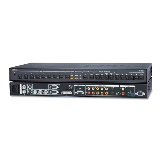
Page 20: Cabling And Rear Panel Views
DVI-D direct digital video to this female DVI connector. This connector supports only a digital DVI source. With the proper adapters, the IN1508 can also be used with HDMI signals. Video output 15-pin HD connectors — Connect an RGB video or progressive/HDTV component video display to this female 15-pin HD connector. -
Page 21: Audio Connections
• If the stripped section of wire is shorter than 3/16”, wires can be easily By default, the audio output follows the video switch. IN1508 Scaling Presentation Switcher • Installation Connect the sleeve(s) to ground ( ). Connecting the sleeve(s) to a negative (-) terminal will damage audio output circuits. -
Page 22: Rs-232 Connection
RS-232 connection Remote port — Connect a host device, such as a computer or touch panel control, to the IN1508 switcher via this 9-pin D connector for serial RS-232 control (figure 2-5). Female Figure 2-5 — Remote port pin assignments See chapter 4, “Serial Communications”, for definitions of the SIS commands. - Page 23 Installation, cont’d IN1508 Scaling Presentation Switcher • Installation...
-
Page 24: Chapter 3 • Operation
IN1508 Scaling Presentation Switcher Chapter Three Operation Front Panel Controls and Indicators Remote Control Buttons Operations Optimizing the Video Optimizing the Audio Troubleshooting... -
Page 25: Front Panel Controls And Indicators
Infrared sensor Infrared remote sensor — This sensor receives infrared (IR) signals from the included IN1508 remote control. The IR remote control must be pointed within 30 degrees of this sensor (figure 3-2) for best results. See “Remote Control Buttons”, later in this chapter, for operation of the remote control. -
Page 26: Input Controls
Input buttons — The Input 1 through Input 8 buttons (figure 3-3) select the associated video input to scale and output. The switch can be a cut or a fade, depending on the switch mode; see “Fade Switch selection box”, on page 3-24. -
Page 27: Output Rate Selection
60 Hz with each resolution selection using the Output Rate button. Eight IN1508 output resolutions are not available from the front panel. These eight resolutions can be selected using the menu system (see “Resolution selection box”, on page 3-21) and SIS commands (see chapter 4, “Serial... -
Page 28: Picture-In-Picture Controls
Unlike when PIP mode is on, however, the input that is replaced in the main window is not displayed in the PIP window. IN1508 Scaling Presentation Switcher • Operation... -
Page 29: Picture Controls Buttons
MENU Figure 3-7 — Menu control buttons Menu button — The Menu button enters the IN1508’s main menu system and backs out of the currently active submenu or selection. See “Main menu system”, on page 3-16, and “Picture adjustments”, on page 3-25, for details. -
Page 30: Remote Control Buttons
Enter button — The Enter button: • Activates a highlighted submenu or function in the IN1508 main menu system. • Exits a slider-type status indicator bar control. • Saves a changed value in a selection box control. See “Main menu system”, on page 3-16, and “Picture adjustments”, on page 3-25, for details. - Page 31 Use the Menu control Enter button — The Enter button: • Activates a highlighted submenu or function in the IN1508 main menu system. • Exits a slider-type status indicator bar control.
-
Page 32: Operations
LED and a secondary input LED are also lit. The selected input, the picture adjustments, and other current settings are saved in non-volatile memory. When power is applied, the latest configuration is retrieved. IN1508 Scaling Presentation Switcher • Operation Color Tint... -
Page 33: Input Selection Operation
Unlike when PIP mode is on, however, the input that is replaced in the main window is not displayed in the PIP window. 3-10 IN1508 Scaling Presentation Switcher • Operation... - Page 34 4:3 Monitor SWAP Press Green Uneven Frequency Rolloff Response Rolloff Output 100k 1000 Voltage Frequency (Hz) IN1508 Scaling Presentation Switcher • Operation RGB 192 Uneven Frequency Rolloff Response Rolloff Output 100k 1000 Voltage Frequency (Hz) Input 8 IN1508 SCALING PRESENTATION SWITCHER...
-
Page 35: Menu System Operation
In figure 3-10, and all other flowcharts in this chapter, solid lines indicate screen changes initiated by the operator. Dashed lines indicate screen changes that are the result of a timeout function. menu display Menu Menu EXTRON ELECTRONICS IN1508 SCALING PRESENTATION SWITCHER Enter INPUT Center Center Center Size... -
Page 36: Selection Boxes And Status Indicator Bars
Enter button — Press the front panel or IR remote control Enter button to: • Activate a highlighted submenu or function in the IN1508 main menu system • Exit a slider-type status indicator bar control •... -
Page 37: Selection Box Control
Figure 3-12 — Accessing and operating typical status indicator bars 3-14 IN1508 Scaling Presentation Switcher • Operation buttons to move the button. and buttons to shift the “slides” to the right and left, increasing and buttons. If you decide that... - Page 38 To make another adjustment to the same input, return to step 2. To adjust another input, select that input. The switcher clears the on-screen displays. Return to step 2. Allow the on-screen display timeout to occur. IN1508 Scaling Presentation Switcher • Operation buttons to highlight the buttons to and buttons to...
-
Page 39: Main Menu System
OUTPUT Timeout Menu AUDIO Timeout Menu ADVANCED Timeout Figure 3-13 — Input submenu flowchart 3-16 IN1508 Scaling Presentation Switcher • Operation buttons to highlight the desired selection and press the Enter Menu Enter Menu Center Center Center Timeout Menu Menu... -
Page 40: Center Selection
Use the front panel or IR remote control aspect ratio. Press the Enter button to change to the highlighted value. The default is 4:3. IN1508 Scaling Presentation Switcher • Operation buttons to highlight the horizontal (H) and buttons to and buttons... -
Page 41: Advanced Screen
Timeout Menu AUDIO Timeout Menu ADVANCED Timeout Figure 3-14 — Picture submenu flowchart 3-18 IN1508 Scaling Presentation Switcher • Operation buttons to highlight the desired buttons to highlight the desired status indicator bar. Timeout menu display Menu Enter Brightness Brightness... -
Page 42: Brightness Status Indicator Bar
Use the front panel or IR remote control decrease the sharpness filtering through a range of 0 to 128. The default setting is 64. IN1508 Scaling Presentation Switcher • Operation and buttons to adjust the and buttons to adjust the contrast... -
Page 43: Output Submenu
Timeout Menu ADVANCED Timeout Figure 3-15 — Output submenu flowchart 3-20 IN1508 Scaling Presentation Switcher • Operation buttons to highlight the desired selection and press the Enter button. Press Enter to Timeout select a change. 640 x 480 800 x 600... -
Page 44: Resolution Selection Box
To select a different sync polarity, use the front panel or IR remote control button to highlight the desired sync format and press the Enter button. The default setting is H–/V–. IN1508 Scaling Presentation Switcher • Operation • 1280 x 768 • 1280 x 800 •... -
Page 45: Signal Type Selection Box
IR remote control through a range of –53 dB to +9 dB. The default setting is 0 dB, no gain or attenuation. 3-22 IN1508 Scaling Presentation Switcher • Operation button to highlight the desired sync type and menu Menu Timeout... -
Page 46: Audio Delay Selection Box
On or Off and press the Enter button. If a different input is selected (see and the newly selected input is scaled and displayed. IN1508 Scaling Presentation Switcher • Operation buttons to select On or Press Enter to select a change. -
Page 47: Swap Selection
The Fade Switch selection box provides the ability to select between cuts and fades when you select a new input. A fade switch fades the output to black, switches to the new input, and then fades in from black. A cut selects the new input with no masking affect. -
Page 48: Performing A System Reset From The Front Panel
IR remote control (figure 3-19 on page 3-26). Shortcuts for the zoom, pan, aspect ratio, sharpness, and pixel phase shift are available from the IR remote control only (figure 3-20 on page 3-27). IN1508 Scaling Presentation Switcher • Operation zXXX SIS command (see chapter 4,... - Page 49 Figure 3-19 — Picture adjustments flowchart, front panel and IR remote control buttons 3-26 IN1508 Scaling Presentation Switcher • Operation Window Center Window Center Window Center Timeout...
- Page 50 Vertical Start status indicator bars, which are advanced adjustments that should be attempted only by knowledgeable A/V professionals. See “Horizontal Start and Vertical Start status indicator bars”, on page 3-35. IN1508 Scaling Presentation Switcher • Operation = IR remote control buttons to highlight the...
- Page 51 Menu > Picture > Contrast in the main menu system (see “Contrast status indicator bar”, on page 3-19). 3-28 IN1508 Scaling Presentation Switcher • Operation PIP is off — Center adjusts the horizontal and vertical position of the main image on the monitor.
- Page 52 Repeat steps 1 and 2 for each image adjustment to be made for that input. If you want to set picture adjustment on another input, press the appropriate input button. IN1508 Scaling Presentation Switcher • Operation and buttons to toggle back and 3-29...
-
Page 53: Front Panel Security Lockout
Operation, cont’d Front panel security lockout The front panel security lockout limits the operation of the IN1508 from the front panel. When the switcher’s front panel is locked out, all of the front panel image adjustment functions are disabled. You can still select inputs. -
Page 54: Crt Displays - Selecting The Optimum Resolution
60 Hz for most LCD, plasma, D-ILA, and DLP projectors. Higher refresh rates are not recommended for these display technologies. They usually do not improve the image and may cause compatibility problems. IN1508 Scaling Presentation Switcher • Operation 3-31... - Page 55 " 5 " 8 " 8 " 0 " 2 " 0 " 0 " 0 " 0 t i j , c i 3-32 IN1508 Scaling Presentation Switcher • Operation s t i t i j " 2 " 0...
-
Page 56: Input Submenu's Advanced Selections
V-Start V-Start V-Start Aspect Aspect Aspect * These variables are dependent on the input resolution and output resolution. Enter IN1508 Scaling Presentation Switcher • Operation (Variable*) Timeout (Variable*) (Variable*) (Variable*) (0 to 62) Inputs 1 - 4 (0 to 200) - Page 57 Use these controls to match the input video signal and to frame the active area. The active pixels and total pixels adjustments are interactive. Setting one of these variables may require adjusting the other. 3-34 IN1508 Scaling Presentation Switcher • Operation Blanking Area Active Area Horizontal...
-
Page 58: Horizontal Start And Vertical Start Status Indicator Bars
If the horizontal start adjustment is set to less than the amount of actual blanking, the IN1508 starts scaling the input before the start of the active image. This early scaling results in a blank border on the left side and cropping on the right side, and looks as if the image is shifted to the right. -
Page 59: Active Pixels And Active Lines Status Indicator Bars
Figure 3-25 — Incorrect active area setting Similarly, if the number of active image lines that the IN1508 is set to scale is less than the amount of actual active lines that are input, the IN1508 scales only the set active area and skips some of the input lines. - Page 60 Adjust the Active Pixels status indicator bar to increase and decrease the number of active pixels, shifting the starting period horizontally on the screen. Adjust the Active Lines status indicator bar to increase and decrease the number of lines. IN1508 Scaling Presentation Switcher • Operation ) t l 3-37...
-
Page 61: Total Pixels Status Indicator Bar
The phase control adjusts the amount of phase shift applied to the input video signal. Use the front panel or IR remote control increase or decrease the amount of phase shift through a range of 0 to 31. 3-38 IN1508 Scaling Presentation Switcher • Operation Blanking Area Active Area... -
Page 62: Optimizing The Audio
Ensure that the input selected is active. Ensure that the proper signal format is supplied. Check the cabling and make corrections as necessary. Call the Extron S IN1508 Scaling Presentation Switcher • Operation Sales & Technical Support Hotline if necessary. 3-39... -
Page 63: Specific Problems
The source is incorrect. Ensure that the source is connected to the correct input and that the volume has not been turned down or muted. The output is incorrect. The IN1508 outputs line level audio only. Ensure that it is connected to a mixer/amplifier or to amplified speakers. - Page 64 Vertical position may be set too far to the top. and shift the image down. Display may be set incorrectly. IN1508 Scaling Presentation Switcher • Operation Solution Pixels and reduce the setting to match the input signal. Select Picture>Advanced>Active Pixels and increase the setting to match the input signal.
- Page 65 Some characters are too soft. Total pixels setting cannot be decreased. 3-42 IN1508 Scaling Presentation Switcher • Operation Possible cause Solution Select Picture>Advanced> may be set too low. V Start and increase the setting to match the input signal.
- Page 66 Active pixels setting may be too high. Active lines setting Vertical start. may be too high. IN1508 Scaling Presentation Switcher • Operation Solution Select Picture>Advanced>Active Pixels and increase the setting to match the input signal. Select Picture>Advanced>H Start and reduce the setting to match the input signal.
- Page 67 Operation, cont’d 3-44 IN1508 Scaling Presentation Switcher • Operation...
-
Page 68: Chapter 4 • Serial Communications
IN1508 Video Scaler and Switcher Chapter Four Serial Communications Host-to-Switcher Instructions Switcher-Initiated Messages Switcher Error Responses Using the Command/Response Table... -
Page 69: Host-To-Switcher Instructions
When a power-up occurs, the switcher responds by sending the following message to the host: Copyright 2005, Extron Electronics, IN1508, Version x.xx Version x.xx is the firmware version number. The switcher does not expect a response from the host; but, for example, the host program might request a new status. -
Page 70: Using The Command/Response Table
= Gain value (numeric dB value, 0 to +9) = Attenuation value (numeric dB value, -1 to -53) IN1508 Scaling Presentation Switcher • Serial Communications = Gain/attenuation (-53 dB to +9 dB, each step = 1 dB) = Output volume (0 to 100) -
Page 71: Command/Response Table For Sis Commands
–T View the tint value Brightness Set a specific brightness value Increment brightness value Decrement brightness value –Y View the brightness value IN1508 Scaling Presentation Switcher • Serial Communications Response (switcher to host) Chn02 •Aud •Vid Rte5*3 Additional description Select video and audio input Select video and audio input 2. - Page 72 Set a vertical start value Example: Increment vertical start value Decrement vertical start value –( View the vertical start value IN1508 Scaling Presentation Switcher • Serial Communications Response Additional description (switcher to host) Specify the contrast adjustment. Increase the contrast by one.
- Page 73 View the output volume Audio delay Set the audio delay on Set the audio delay off View the audio delay Example: IN1508 Scaling Presentation Switcher • Serial Communications Response Additional description (switcher to host) Phs6 Use a pixel phase setting of 6.
- Page 74 Information requests Query firmware version Request part number Request general information Resets Zap all IN1508 settings zXXX IN1508 Scaling Presentation Switcher • Serial Communications Response Additional description (switcher to host) Mute the audio output. Unmute the audio output. Audio mute is Exe1 Lock front panel adjustments;...
-
Page 75: Command/Response Table For Special Function Sis Commands
Set blue screen (blue & sync output only) Example: 1*8# View blue mode on/off IN1508 Scaling Presentation Switcher • Serial Communications # where is the value or variable is the function number (such as #, where is the function number. - Page 76 View the audio follow setting Example: IR receiver enable Disable IR receiver 0*65# Enable IR receiver 1*65# Read IR receiver enable IN1508 Scaling Presentation Switcher • Serial Communications Response Additional description (switcher to host) Asp1 Asp0 Asp0 The aspect ratio is set to 4:3.
- Page 77 When DVI auto-detect is enabled, the horizontal start and vertical start adjustments are disabled. If you need to change these settings, disable DVI auto-detect. Disable DVI auto detect 0*76# Enable DVI auto-detect 1*76# Read DVI auto-detect 4-10 IN1508 Scaling Presentation Switcher • Serial Communications Response (switcher to host) *41# DDC15*2 IRD80 DVI81 DVI8...
-
Page 78: Appendix A • Specifications And Part Numbers
IN1508 Scaling Presentation Switcher A ppendix A Specifications and Part Numbers Specifications Part Numbers... -
Page 79: Video Processing
Input level ... 0 V to 5 Vp-p Output level ... TTL: 5.0 Vp-p, unterminated Input impedance ... 75 ohms Output impedance ... 75 ohms IN1508 Scaling Presentation Switcher • Specifications and Part Numbers 1,2,3 , 800x600 1,2,3 , 852 x 800... -
Page 80: Audio Output
Enclosure dimensions ... 1.75" H x 17.5" W x 8.5" D (1U high, full rack wide) 4.4 cm H x 44.4 cm W x 21.6 cm D (Depth excludes connectors and knobs. Width excludes rack ears.) Product weight ... 7.0 lbs (3.2 kg) IN1508 Scaling Presentation Switcher • Specifications and Part Numbers ™... -
Page 81: Included Parts
All nominal levels are at ±10%. Specifications are subject to change without notice. Part Numbers Included parts These items are included in each order for an IN1508: Included parts IN1508 Scaling Presentation Switcher IN1508 infrared remote control Rubber feet (self-adhesive) (4) -
Page 82: High Performance Dvi Cables
IN9700/25 DVI male to male 25' (7.6 meters) IN9700/35 DVI male to male 35' (10.6 meters) IN9700/50 DVI male to male 50' (15.2 meters) IN9700/75 DVI male to male 75' (22.8 meters) IN1508 Scaling Presentation Switcher • Specifications and Part Numbers Part number 26-584-06 26-584-01... - Page 83 Specifications and Part Numbers, cont’d IN1508 Scaling Presentation Switcher • Specifications and Part Numbers...
-
Page 84: Extron's Warranty
Extron Electronics warrants this product against defects in materials and workmanship for a period of three years from the date of purchase. In the event of malfunction during the warranty period attributable directly to faulty workmanship and/or materials, Extron Electronics will, at its option, repair or replace said products or components, to whatever extent it shall deem necessary to restore said product to proper operating condition, provided that it is returned within the warranty period, with proof of purchase and description of malfunction to:... - Page 85 Extron Electronics, USA 1230 South Lewis Street Anaheim, CA 92805 800.633.9876 714.491.1500 FAX 714.491.1517 www.extron.com Extron Electronics, Asia Extron Electronics, Europe 135 Joo Seng Rd. #04-01 Beeldschermweg 6C PM Industrial Bldg., Singapore 368363 3821 AH Amersfoort, The Netherlands +800.7339.8766 +65.6383.4400 +800.3987.6673 +31.33.453.4040 FAX +65.6383.4664 FAX +31.33.453.4050...
Need help?
Do you have a question about the IN1508 and is the answer not in the manual?
Questions and answers