
Related Manuals for Tennant 7300


Summary of Contents for Tennant 7300
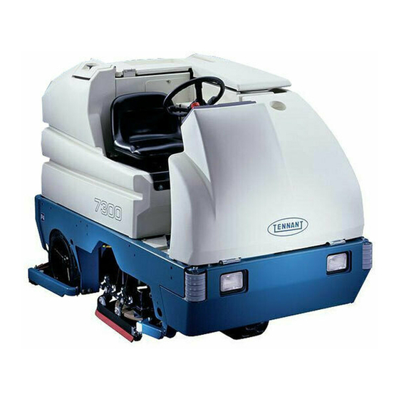
- Page 1 7300 Rider Scrubber Operator Manual The Safe Scrubbing Alternative ES Extended Scrub System North America / International 330610 Rev. 12 (06-2009) *330610* www.tennantco.com Home Find... Go To..
- Page 2 Phone: (800) 553--8033 or (763) 513--2850 www.tennantco.com Thermo- -Sentry, SmartRelease, SuperScrub, and MaxPro are US registered and unregistered trademarks of Tennant Company. Specifications and parts are subject to change without notice. Copyright E 2000 - - 2002, 2004 - - 2009 TENNANT Company, Printed in U.S.A.
-
Page 3: Table Of Contents
....ec--H2O System (Option) ....7300 330610 (6- -09) Home Find... Go To.. - Page 4 ....Flushing Antifreeze From The ec--H2O Module ....7300 330610 (6- -09) Home Find... Go To..
-
Page 5: Safety Precautions
Do not pick up. protection when handling vinegar. - - Avoid contact with battery acid. FOR SAFETY: - - Use Tennant supplied or equivalent replacement parts. 1. Do not operate machine: - - Unless trained and authorized. 7. When loading/unloading machine... - Page 6 ON THE INSIDE OF THE SOLUTION TANK COMPARTMENT. COVER. FLAMMABLE SPILLS LABEL - - LOCATED ON THE INSIDE OF THE BATTERY CHARGING LABEL - - LOCATED ON OPERATOR COMPARTMENT. THE LINTEL. 353374 7300 330610 (7- -00) Home Find... Go To..
-
Page 7: Operation
Tennant representative. - Order parts and supplies directly from your authorized Tennant representative. Use the parts manual provided when ordering parts. - After the first 50 hours of operation, follow the recommended procedures stated in the MAINTENANCE CHART. -
Page 8: Machine Components
E. Solution tank F. Rear squeegee G. Side squeegee H. Solution tank drain Recovery tank drain J. Rear wheel K. Side Brush (Option) L. FaST solution system ec- H2O System Module (Option) 7300 330610 (6- -09) Home Find... Go To.. -
Page 9: Symbol Definitions
Scrub brush edge clean Circuit breaker #5 Squeegee up Circuit breaker #6 Squeegee down Circuit breaker #7 Key switch Circuit breaker #8 Operating lights Circuit breaker #9 Hazard light (option) Circuit breaker #10 7300 330610 (12- -01) Home Find... Go To.. -
Page 10: Symbol Definitions
Detergent flow heavy (option) Circuit breaker #17 Detergent flow off (option) Circuit breaker #18 Side brush down and on (option) Diagnostics Side Brush up and off (option) Power Wand (option) ec--H20 (option) Jackpoint 7300 330610 (6- -09) Home Find... Go To.. -
Page 11: Controls And Instruments
L. Solution flow lever M. Display screen N. Multi- -function switches (6) O. TENNANT logo switch P. Control panel Q. FaST switch ec- H2O system on/off switch (option) R. ec- H2O system indicator light (option) 7300 330610 (6- -09) Home Find... Go To.. -
Page 12: Operation Of Controls
Use the brake pedal to stop the machine. Forward: Press the top of the directional pedal with the toe of your foot. 7300 330610 (6- -09) Home Find... Go To.. -
Page 13: Steering Wheel
The steering wheel controls the machine’s direction. The machine is very responsive to the steering wheel movements. Left: Turn the steering wheel to the left. Right: Turn the steering wheel to the right. 7300 330610 (6- -09) Home Find... Go To.. -
Page 14: On-Off Key Switch
On: Turn the key clockwise all the way. Off: Turn the key counter-clockwise. HORN BUTTON The horn button operates the horn. Sound: Press the button. 7300 330610 (6- -00) Home Find... Go To.. -
Page 15: Power Kill Switch
POWER WAND SWITCH (OPTION) The power wand switch turns on and off the power wand solution system option. On: Press the top of the switch. Off: Press the bottom of the switch. 7300 330610 (6- -00) Home Find... Go To.. -
Page 16: Solution Flow Lever
Enable the FaST system 2: Press the bottom of the switch to the high FaST system solution flow position. NOTE: The FaST system will not start until the directional pedal is pressed. 7300 330610 (6- -09) Home Find... Go To.. -
Page 17: Ec--H20 Switch
12 : 16 PM that prompts the operator when to perform routine machine maintenance. By pressing the TENNANT logo switch, the 0020 operator can cycle the control panel display through the different function screens. Each... -
Page 18: Changing Display Language
7. Turn the machine power off, and the new ENGLISH language will be stored in the control panel. Enable sweep Restrict Press. 353555 7300 330610 (12- -00) Home Find... Go To.. -
Page 19: Battery Discharge Indicator
The hourmeter will record time when the machine is propelling or when the vacuum fan is operating. This information is useful when maintaining the machine. 12 : 16 PM 0020 353550 7300 330610 (12- -00) Home Find... Go To.. -
Page 20: Display Clock
(--) icon. 12 : 00 AM 0 1 / 01 / 97 8. Exit the ADJUST TIME function by pressing the TENNANT logo switch. 9. Turn the key to the off position. 353557 7300 330610 (12- -00) Home Find... Go To.. -
Page 21: Scrub Switch
Super Scrub switch once. See the SUPER SCRUB SWITCH section of the manual. The pressure setting selected when the scrub switch is released will be the new default brush pressure setting. 353563 7300 330610 (6- -09) Home Find... Go To.. -
Page 22: Super Scrub Switch (For Machines Without Optional Side Brush)
On: Pressing the scrub switch twice quickly. One large arrow above the brush icon will appear. Off: Press the switch (Super Scrub will automatically shut off after 30 seconds). The large arrow above the brush icon will disappear. 353562 7300 330610 (6- -09) Home Find... Go To.. -
Page 23: Recovery Tank Full Indicator
On: Press the switch during normal scrubbing. The indicator light next to the switch will illuminate. Off: Press the switch again. The indicator light next to the switch will go off. 353562 7300 330610 (9- -02) Home Find... Go To.. -
Page 24: Rear Squeegee Switch
NOTE: The rear squeegee will raise and the scrubbing vacuum fan will shut off after a short delay when the scrubbing operations are shut off. 7300 330610 (12- -00) Home Find... Go To.. -
Page 25: Side Brush Switch (Option)
Up and Off: Press the side brush switch. The indicator light next to the switch will go out, then the side brush will stop and raise. 7300 330610 (9- -02) Home Find... Go To.. -
Page 26: Detergent Pump Switch (Option)
This will happen if one or more of the maintenance timers goes past its recommended interval. Each time the required maintenance function is performed, the timer for that function should be reset. 0020 353558 7300 330610 (6- -09) Home Find... Go To.. -
Page 27: Resetting The Maintenance Timers
The operator can scroll through the four maintenance function 353559 screens by pressing the logo switch. To determine which routine maintenance function each icon represents, see the SYMBOL DEFINITIONS section of this manual. 7300 330610 (12- -00) Home Find... Go To.. -
Page 28: Disabling The Maintenance Mode
Enable Maint. default maintenance intervals, press the switch next to Display Maint.. Press the logo switch to scroll through the maintenance function screens. 353560 7300 330610 (12- -00) Home Find... Go To.. -
Page 29: Fuses
The two actuator fuses are located in the control panel. Fuse Rating Circuit Protected FU 1 150 A Propelling FU 2 10 A Electronic Actuator FU 3 10 A Electronic Actuator 7300 330610 (12- -02) Home Find... Go To.. -
Page 30: Circuit Breakers
Vac Fan #2 (001706- - CB12 25 A Control Board CB13 50 A Center Scrub Motor (000000- -001705) CB13 Open (001706- - CB14 40 A Power Steering Pump CB15 10 A FaST 7300 330610 (2- -04) Home Find... Go To.. - Page 31 Center Scrub Motor This chart shows the magnetic circuit breakers used on machines with an ec- -H20 system. Circuit Breaker Rating Circuit Protected CB16 Water Valve CB17 ec- -H20 Module CB18 Solution Pump 7300 330610 (6- -09) Home Find... Go To..
-
Page 32: Solution Tank Drain Hose (Option)
LATCHES The front machine cover is secured with a latch. Open: Press the raised part of the latch. Close: Press the flat part of the latch. 7300 330610 (6- -00) Home Find... Go To.. -
Page 33: Operator Seat
Decrease angle: Turn the angle adjustment knob clockwise. The weight adjustment knob controls the firmness of the operator’s seat. Increase firmness: Turn the weight adjustment knob clockwise. Decrease firmness: Turn the weight adjustment knob counterclockwise. 7300 330610 (9- -02) Home Find... Go To.. -
Page 34: Side Brush Adjustment Knob (Option)
The side brush adjustment knob controls the amount of contact the side brush has with the surface being swept. Increase: Turn the side brush adjustment knob counter--clockwise. Decrease: Turn the side brush adjustment knob clockwise. 7300 330610 (9- -02) Home Find... Go To.. -
Page 35: How The Machine Works
For specific recommendations, contact your Tennant representative. When finished scrubbing, drain and clean the recovery tank. If using the ES system (option), drain and clean the solution tank, and clean the ES filter. 7300 330610 (9- -02) Home Find... Go To.. -
Page 36: Fast Scrubbing System
FaST system failure. NOTE: Storing or transporting machines equipped with the ES or the FaST system in freezing temperatures requires special procedures. Consult a TENNANT representative for more information. 7300 330610 (6- -09) Home Find... Go To.. -
Page 37: Ec--H2O System (Option)
-H2O solution system. NOTE: Storage or transporting machines equipped with ec- -H2O in freezing temperatures requires special procedures. Follow the freeze protection procedure located in the STORAGE INFORMATION section. 7300 330610 (6- -09) Home Find... Go To.. -
Page 38: Pre-Operation Checklist
- For FaST or ec- -H2O Scrubbing: Check that all conventional cleaning agents/restorers are drained and rinsed from the solution tank. - For FaST or ec- -H2O Scrubbing: Check that the solution tank is filled with clear cool water only. 7300 330610 (6- -09) Home Find... Go To.. -
Page 39: Installing Fast Pak Agent
Do not add cleaning agents in the solution tank. Conventional cleaning agents/restorers may cause failure to the FaST solution system.. 4. Raise the front cover to access the FaST PAK carton. 7300 330610 (6- -09) Home Find... Go To.. - Page 40 If the previous FaST PAK was run dry, it may take up to 7--10 minutes of operation to remove any air pockets in the system before you achieve maximum foaming. 7300 330610 (6- -09) Home Find... Go To..
-
Page 41: Starting The Machine
FOR SAFETY: When starting machine, keep foot on brake and directional pedal in neutral. 2. Turn the machine power on. 3. Release the machine parking brake. 4. Drive the machine to the area to be cleaned. 7300 330610 (6- -09) Home Find... Go To.. -
Page 42: Filling The Tanks
2. Drive the machine to the filling site. 3. Turn the machine power off. 4. Set the parking brake. FOR SAFETY: Before leaving or servicing machine; stop on level surface, set parking brake, turn off machine and remove key. 7300 330610 (6- -09) Home Find... Go To.. - Page 43 NOTE: Floor conditions, water condition, amount of soilage, type of soilage, and brush action all play an important role in determining the type and concentration of detergent used. For specific recommendations, contact your TENNANT representative. 7300 330610 (6- -09) Home Find... Go To..
- Page 44 NOTE: If you DO NOT want to use the ES system, DO NOT put water in the recovery tank. Turn the ESt switch OFF. 9. Close the solution tank cover. 7300 330610 (6- -00) Home Find... Go To..
-
Page 45: Sweeping, Scrubbing And Brush Information
Non-scuff polypropylene scrub brush -- This brush uses a softer, general purpose polypropylene bristle to lift lightly compacted soilage without scuffing high-gloss coated floors. 05939 7300 330610 (9- -02) Home Find... Go To.. - Page 46 NOTE: Cylindrical scrub brushes must be installed with the herringbone patterns on the brushes pointing towards each other for best debris pick up. 7300 330610 (6- -09) Home Find... Go To..
-
Page 47: Scrubbing
-H2O MODULE FLUSH PROCEDURE). NOTE: When the alarm sounds and the light blinks red, the machine will bypass the ec- -H2O system. To continue scrubbing, press the ec- -H2O switch to conventional scrubbing. 7300 330610 (6- -09) Home Find... Go To.. - Page 48 Stop flow: Lower the lever all the way down. NOTE: For machines equipped with cylindrical scrub heads, decrease solution flow rate when turning. 7300 330610 (6- -09) Home Find... Go To..
- Page 49 NOTE: A low battery and a no brush current sensed will also cancel the scrub system. 6. Adjust brush pressure for cleaning application. See the SCRUB SWITCH section of the manual. 353562 7300 330610 (6- -09) Home Find... Go To..
- Page 50 NOTE: A full solution tank will turn off the ES pump 353562 NOTE: If you do not want to use the ES system, make sure the indicator next to the ES switch is off. 353562 7300 330610 (2- -04) Home Find... Go To..
- Page 51 11. Press the side brush button again to restart the side brushes as needed while scrubbing. 12.Drive the machine forward and scrub as required. WARNING: Flammable materials or reactive metals can cause explosion or fire. Do not pick up. 7300 330610 (NIL) Home Find... Go To..
-
Page 52: Double Scrubbing
After a short delay, the rear 12 : 16 PM squeegee will automatically raise and the scrubbing vacuum fan will stop. Continue driving the machine forward until the 0020 vacuum fan shuts off. 353550 7300 330610 (6- -09) Home Find... Go To.. -
Page 53: Draining And Cleaning The Tanks
3. Turn the machine power off. FOR SAFETY: Before leaving or servicing machine; stop on level surface, set parking brake, turn off machine and remove key. 4. Set the parking brake. 7300 330610 (6- -09) Home Find... Go To.. - Page 54 DO NOT allow any water to enter the vacuum fan air intake opening towards the front of the tank. NOTE: DO NOT use steam to clean the tanks. Excessive heat can damage the tanks and components. 7300 330610 (6- -00) Home Find... Go To..
- Page 55 11. ES mode: Lift up the ES filter by the handle until the mesh is exposed and rinse it thoroughly. 12. Rinse off the float sensor(s) on the inside of the recovery tank. 7300 330610 (2- -04) Home Find... Go To..
- Page 56 15. Cylindrical scrub head: Press down on the right side squeegee support guard latch until the right side squeegee support guard opens. Swing the squeegee support guard away from the scrub head. 7300 330610 (6- -00) Home Find... Go To..
- Page 57 20. Place the drain end caps on the tank drain hoses. Push the drain hoses back into the tanks. For machines with the positive solution control drain option, close the drain valve. Remove the hose and connect the drain cap. 7300 330610 (6- -00) Home Find... Go To..
-
Page 58: Stop The Machine
3. Turn the machine power off. 4. Set the machine parking brake. FOR SAFETY: Before leaving or servicing machine; stop on level surface, set parking brake, turn off machine and remove key. 7300 330610 (6- -09) Home Find... Go To.. -
Page 59: Post-Operation Checklist
- Check the service records to determine maintenance requirements. - FaST Scrubbing: If FaST PAK is empty after scrubbing, install a new FaST PAK or connect supply hose to the storage plug. 7300 330610 (2- -04) Home Find... Go To.. -
Page 60: Operation On Inclines
Do not pick up. 1. Turn the machine power off. FOR SAFETY: Before leaving or servicing machine; stop on level surface, turn off machine. 2. Set the parking brake. 7300 330610 (6- -09) Home Find... Go To.. - Page 61 5. Connect the vacuum wand hose and the squeegee suction hose with the adapter. 6. Put together the wand and the wand hose. 10945 7. Turn the machine power on. 7300 330610 (6- -00) Home Find... Go To..
- Page 62 8. Press the rear squeegee switch to turn on the vacuum. 0020 353565 9. Vacuum the floor. 06599 10. When finished, shut off the vacuum with the rear squeegee switch. 12 : 16 PM 0020 353550 7300 330610 (12- -00) Home Find... Go To..
- Page 63 13. Reconnect the squeegee suction hose to the top of the squeegee. 14. Clean and rinse the vacuum wand equipment. 15. Secure the vacuum wand equipment on top of the tank cover. 7300 330610 (6- -00) Home Find... Go To..
-
Page 64: Power Wand
1. Turn the machine power off. FOR SAFETY: Before leaving or servicing machine; stop on level surface, turn off machine. 2. Set the parking brake. 3. Remove the power wand equipment from the tank cover. 7300 330610 (6- -09) Home Find... Go To.. - Page 65 10945 6. Attach the end of solution hose to the quick-disconnect. Push the connector in until it stops. Pull on the hose to make sure it is connected. 7300 330610 (6- -00) Home Find... Go To..
- Page 66 07320 8. Turn the machine power on. 9. Press the rear squeegee switch to turn on the vacuum. NOTE: The rear squeegee will also lower. 12 : 16 PM 0020 353565 7300 330610 (12- -00) Home Find... Go To..
- Page 67 Scrub the floor with the brush side of the cleaning tool. 06601 12. Vacuum up the solution by turning over the cleaning tool so the squeegee side is down. 06202 7300 330610 (6- -00) Home Find... Go To..
- Page 68 13. When finished, press the bottom of the power wand switch to turn off the power wand. 14. Press the rear squeegee switch to shut off the vacuum. 12 : 16 PM 0020 353550 7300 330610 (12- -00) Home Find... Go To..
- Page 69 18. Reconnect the squeegee suction hose to the squeegee. 19. Disconnect the other ends of the solution and vacuum hoses from the power wand. 20. Secure the power wand equipment on top of the tank cover. 07321 7300 330610 (6- -00) Home Find... Go To..
-
Page 70: Machine Troubleshooting
Turn ES switch on Manual control valve closed Open valve more Brush pressure light blinks Brush pressure set to heavy for the Decrease brush pressure setting and changes to a lower application pressure setting. 7300 330610 (6- -09) Home Find... Go To.. - Page 71 Defective light or module Contact Service Center ec- -H2O system indicator light does not turn on ec- H2O Model: Clogged module Contact Service Center No water flow Defective solution pump Replace solution pump 7300 330610 (6- -09) Home Find... Go To..
-
Page 72: Maintenance
Clean and flush Debris trough Check and clean (Cylindrical brushes only) FaST PAK supply hose Clean and connect hose to stor- and connector ing plug when not in use Machine Check for leaks 7300 330610 (2- -04) Home Find... Go To.. - Page 73 1, 2 FaST injector filters Replace (S/N 003747-- SPL -- Special lubricant, Lubriplate EMB grease (Tennant part no. 01433--1) GL -- SAE 90 weight gear lubricant HYDO -- TENNANT or approved hydraulic fluid DW -- Distilled water 7300 330610 (6- -09) Home Find...
-
Page 74: Lubrication
The bearing cavity is full when grease comes out of the fittings, or out of the top seal. Lubricate with Lubriplate EMB grease (Tennant part no. 01433--1) every 100 hours of machine operation, or after steam cleaning the gearbox area. -
Page 75: Scrub Head Drag Link Arms (S/N 000000--003695)
(S/N 000000- -003695) The scrub head drag link arms have a grease fitting at each of the pivot points. Lubricate with Lubriplate EMB grease (Tennant Part No. 01433--1) every 100 hours of operation. The MaxPro 1000 disk scrub head has four link arms that need lubrication. -
Page 76: Rear Wheel Bearings
REAR WHEEL BEARINGS Inspect the rear wheel bearings for seal damage, and repack and adjust every 500 hours of operation. Use Lubriplate EMB grease (Tennant part number 01433--1). STEERING GEAR CHAIN The steering gear chain is located by the foot pedals. -
Page 77: Hydraulics (Option)
Damage to the machine hydraulic system may result. The reservoir has a built--in filter outlet that filters hydraulic fluid before it enters the system. Replace the filter every 500 hours of operation. 7300 330610 (12- -01) Home Find... Go To.. -
Page 78: Hydraulic Fluid
The quality and condition of the hydraulic fluid play a very important role in how well the machine operates. Tennant’s hydraulic fluid is specially selected to meet the needs of Tennant machines. Tennant’s hydraulic fluids provide a longer life for the hydraulic components. -
Page 79: Batteries
If one or more of the battery cells test lower than the other battery cells (0.050 or more), the cell is damaged, shorted, or is about to fail. 04380 7300 330610 (7- -00) Home Find... Go To.. -
Page 80: Charging The Batteries
WARNING: Batteries emit hydrogen gas. Explosion or fire can result. Keep sparks and open flame away. Keep covers open when charging. 4. Open the rear battery compartment door. 7300 330610 (6- -09) Home Find... Go To.. - Page 81 9. Plug the battery charger into the wall outlet. NOTE: If the red “ABNORMAL CYCLE” lamp lights when the TENNANT charger is plugged into a wall outlet, the charger can not charge the battery and there is something wrong with the battery.
-
Page 82: Control Panel
4. Continue pressing the logo switch for 15 seconds or until the down pressure display screen appears. 12 : 16 PM 5. Press and release the TENNANT logo button two more times. The SELF TEST screen will appear on the display. 0020... - Page 83 Note the error Self Test message displayed, and contact the service personnel. 9. Turn off the diagnostic by turning off the 0020 machine power. 353561 7300 330610 (6- -09) Home Find... Go To..
-
Page 84: Electric Motors
Do not steam clean or spray the panel with water because the electrical system may be damaged. NOTE: A static discharge grounding strap should be used when servicing the electronic circuitry. 7300 330610 (6- -00) Home Find... Go To.. -
Page 85: Scrub Head
500 hours of operation. SCRUB HEAD ADJUSTMENTS The cylindrical scrub head is factory adjusted, and the measurements should not be changed unless scrub head parts are damaged or are replaced. 7300 330610 (5- -01) Home Find... Go To.. -
Page 86: Scrub Brushes
3. Raise the side squeegee and lock in the up position using the side squeegee double scrub latches. 7300 330610 (6- -09) Home Find... Go To.. - Page 87 Pull the brush out from under the scrub head. 6. Place the new scrub brush on the floor in front of the scrub head. Push the brush under the scrub head. 7300 330610 (6- -00) Home Find... Go To..
- Page 88 10.Lift up on the side squeegee while releasing the side squeegee double scrub latches. Lower the side squeegee to the down position. 11. Repeat for the other brush. 7300 330610 (6- -00) Home Find... Go To..
-
Page 89: Cylindrical Brushes
A polish mark will remain on the floor. 4. Raise the scrub head and move the machine away from the chalked area. Turn the machine power off. 7300 330610 (6- -09) Home Find... Go To.. - Page 90 A. Open the side squeegee support door with the latch. Swing the support door outward to access the idler support cover. B. Loosen the larger mounting screw on the outside of the idler door. 7300 330610 (6- -00) Home Find... Go To..
- Page 91 Level the scrub head by turning the top scrub head drag link arm on both sides of the scrub head. Check the brush patterns again and readjust as necessary until both patterns are the same. 7300 330610 (6- -00) Home Find... Go To..
-
Page 92: Replacing The Cylindrical Brushes
4. Lift up on the idler support latch to release the idler support cover. 5. Pull the idler plug off the brush, and pull the old brush out of the scrub head. 7300 330610 (5- -01) Home Find... Go To.. - Page 93 9. Firmly close the side squeegee support door. Check that the door bumper is tight against the debris tray. 10.Repeat for the other brush on the other side of the scrub head. 7300 330610 (7- -00) Home Find... Go To..
-
Page 94: Side Sweeping Brush (Option)
6. Lower the hopper assembly 7. Check the side brush pattern. To increase the bristle contact with the floor, turn the side brush adjustment knob counter-- clockwise. To decrease, turn the side brush adjustment knob clockwise. 7300 330610 (6- -09) Home Find... Go To.. -
Page 95: Solution System
The recovery tank should be drained and cleaned daily, after the solution tank is empty, whenever the float stops the vacuum fan, or the recovery tank full indicator lights. See DRAINING AND CLEANING THE TANKS section of this manual. 7300 330610 (6- -00) Home Find... Go To.. -
Page 96: Solution Tank
THE TANKS section of this manual. ES option: The solution tank should be drained and cleaned daily. Rinse the solution outlet filters at the bottom of the tank through the drain access. 7300 330610 (6- -00) Home Find... Go To.. -
Page 97: Fast System
Remove and clean out the air filter with compressed air after every 200 hours of FaST scrubbing. FOR SAFETY: When servicing machine, wear eye protection when using pressurized air or water. 7300 330610 (6- -09) Home Find... Go To.. -
Page 98: Fast System Air Pump Filter
(S/N 003747- - The FaST system injector filters are located under the FaST--PAK holder. Replace the FaST system injector filters after every 1000 hours of operation. Empty the solution tank before replacing the filters. 7300 330610 (6- -09) Home Find... Go To.. -
Page 99: Ec--H2O Module Flush Procedure
4. Place the ec- -H2O system intake hose into a empty bucket. 5. Turn the key to the on ( I ) position. 7300 330610 (6- -09) Home Find... Go To.. - Page 100 If the ec--H2O system indicator light continues to flash, repeat the flush procedure. If the problem persists, contact an Authorized Service Center. 11. Reconnect the siphon hose to the retainer and neatly coil the hose for storage. 7300 330610 (6- -09) Home Find... Go To..
-
Page 101: Squeegees
FOR SAFETY: Before leaving or servicing machine; stop on level surface, set parking brake, turn off machine and remove key. 4. Look at the deflection of the squeegee blade, over the full length of the squeegee blade. 7300 330610 (NIL) Home Find... Go To.. -
Page 102: Adjusting Rear Squeegee Blade Deflection
4. Look at the deflection of the squeegee blade. The correct amount of deflection is 15 to 20 mm 15 to 20 mm. 03719 7300 330610 (6- -00) Home Find... Go To.. -
Page 103: Removing The Rear Squeegee Assembly
2. Turn the machine power off and set the parking brake. 3. Remove the squeegee suction hose from the top of the rear squeegee. 4. Loosen both squeegee mounting knobs. 5. Pull the squeegee off the machine. 7300 330610 (7- -00) Home Find... Go To.. -
Page 104: Side Squeegee
1. Make sure the squeegee is raised off the floor. 2. Turn the machine power off and set the parking brake. FOR SAFETY: Before leaving or servicing machine; stop on level surface, turn off machine. 7300 330610 (6- -00) Home Find... Go To.. - Page 105 8. Mount the retainer strip back over the squeegee blades. Secure the retainer strip with the retainer strip clamp. Adjust the rear squeegee as described in LEVELING THE REAR SQUEEGEE and ADJUSTING REAR SQUEEGEE BLADE DEFLECTION. 7300 330610 (6- -00) Home Find... Go To..
-
Page 106: Side Squeegees Blades
6. Replace the retainer bracket, deflector, clevis pin, and cotter pin. 7. Repeat for the side squeegee on the other side of the scrub head. 7300 330610 (6- -00) Home Find... Go To.. -
Page 107: Belts And Chains
STATIC DRAG CHAIN A static drag chain prevents the buildup of static electricity in the machine. The chain is attached to the transaxle. Make sure the chain is always touching the floor. 7300 330610 (5- -01) Home Find... Go To.. -
Page 108: Skirts And Seals
The front cover seals are located around the edge of the opening between the front cover, operator compartment, and solution recovery tank. Check the seals for wear or damage every 100 hours of operation. 7300 330610 (5- -01) Home Find... Go To.. -
Page 109: Solution Tank Cover Seal
Check the seal for wear or damage every 100 hours of operation. RECOVERY TANK COVER SEAL The recovery tank cover seal is located under the recovery tank cover. Check the seal for wear or damage every 100 hours of operation. 7300 330610 (6- -00) Home Find... Go To.. -
Page 110: Brakes And Tires
FRONT WHEEL Torque the front wheel nuts twice in the pattern shown to 122 to 155 Nm (87--111 ft. lbs) after the first 50 hours of operation, and every 500 hours of operation. 7300 330610 (5- -01) Home Find... Go To.. -
Page 111: Pushing, Towing, And Transporting The Machine
Do not drive the machine onto the truck or trailer unless the loading surface is horizontal AND is 380 mm (15in) or less from the ground. 7300 330610 (7- -00) Home Find... Go To.. - Page 112 FOR SAFETY: When unloading machine off truck or trailer, use winch. Do not drive the machine off the truck or trailer unless the loading surface is horizontal AND 380 mm (15in) or less from the ground. 7300 330610 (7- -00) Home Find... Go To..
-
Page 113: Machine Jacking
FOR SAFETY: When servicing machine, block machine tires before jacking machine up. FOR SAFETY: When servicing machine, jack machine up at designated locations only. Block machine up with jack stands. 7300 330610 (7- -00) Home Find... Go To.. -
Page 114: Storage Information
NOTE: Storing or transporting machines equipped with the ES or the FaST system in freezing temperatures requires special procedures. Consult a TENNANT representative for more information. FREEZE PROTECTION (MACHINES WITHOUT OPTIONAL ec- H2O SYSTEM) 1. Drain the solution tank and recovery tank of all water. -
Page 115: Freeze Protecting The Ec--H2O System
7. Disconnect the siphon hose from the ec- -H2O system intake hose. 8. Reconnect ec- -H20 intake hose to the solution supply hose. 7300 330610 (6- -09) Home Find... Go To.. - Page 116 See FLUSHING ANTIFREEZE FROM ec- -H2O MODULE section of this manual. 10.If machine is equipped power wand option, operate the the wand for a few seconds to protect the pump. 7300 330610 (6- -09) Home Find... Go To..
-
Page 117: Flushing Antifreeze From The Ec--H2O Module
-H2O system, the ec- -H2O module may detect an error and not function (ec- -H2O indicator light will turn red). If this occurs, reset key and repeat the flush procedure. 7300 330610 (6- -09) Home Find... Go To.. -
Page 118: Specifications
2.14 CC/Minute (0.07 Liquid Ounces/Minute) High concentrate flow rate 4.28 CC/Minute (0.14 Liquid Ounces/Minute) Air pump 36 Volt DC, 0.6 Maximum Amp draw Air pump flow rate 8.7 LPM (0.3 CFM) open flow 7300 330610 (2- -04) Home Find... Go To.. -
Page 119: Power Type
Kw (hp) Electric Motors Scrub brush 0.75 (1) Heavy Duty scrub brush 1.12 (1.5) Vacuum fan 0.63 (0.85) Propelling 3.4 (4.6) Type Phase Chargers 208--240--480 208--240--480 208--240--480 208--240--480 208--240--480 208--240--480 208--240--480 208--240--480 7300 330610 (2- -04) Home Find... Go To.. -
Page 120: Steering
2.35 LPM (0.62 GPM) -- Low (standard) 3.18 LPM (0.84 GPM) -- Low (optional)* 3.80 LPM (1.00 GPM) -- High (standard) *If the optional solution flow rates are required, contact an Authorized Service Center. 7300 330610 (6- -09) Home Find... Go To.. -
Page 121: Machine Dimensions
(56 in) 1300 mm (51 in) 1282 mm (50.5 in) 1145 mm MaxProt1200 (45 in) 1510 mm (59.5 in) 2070 mm (81.5 in) 1450 mm (57 in) FRONT VIEW SIDE VIEW MACHINE DIMENSIONS 7300 330610 (2- -04) Home Find... Go To.. -
Page 122: Index
Dimensions, 116 Steering gear, 105 Directional pedal, 10 Changing message display language, 16 Display clock, 18 Circuit breakers, 28 setting & adjusting, 18 Double scrubbing, 50 Draining and cleaning the tanks, 51–53 7300 330610 (6- -09) Home Find... Go To.. - Page 123 Levers Vacuum fan inlet, 36, 57 Solution flow, 14 Flush antifreeze from ec---H20 module, 115 Steering wheel column tilt, 14 Freeze protection, 112 Freeze protection, ec---H20 system, 113 Front cover seals, 106 7300 330610 (6- -09) Home Find... Go To..
- Page 124 Positive solution control drain, 30 Power wand, 62–69 Power wand switch, 13 Side brush adjustment knob (Option), 32 Side brush switch, 23 Side sweeping brush(es), 92 Solution tank drain hose, 30 Vacuum wand, 58–62 7300 330610 (6- -09) Home Find... Go To..
- Page 125 Staring the machine, 39 Side squeegee blades, 104 Static drag chain, 105 Side squeegees, 102 Steering, 36, 57 Side sweeping brush(es), information, 92 Specifications, 118 Skirts, Scrub head floor, 106 Steering gear chain, 74, 105 7300 330610 (6- -09) Home Find... Go To..
- Page 126 Tanks Recovery, 93 Solution, 94 Tie down locations, 110 Tires, 108–109 Specifications, 118 Towing machine, 109 Transporting machine, 109 Transporting the machine, 109 Troubleshooting, 68 Vacuum wand, 58–62 Wheel nuts, Torque, 108 7300 330610 (6- -09) Home Find... Go To..
Need help?
Do you have a question about the 7300 and is the answer not in the manual?
Questions and answers