Table of Contents
Advertisement
Quick Links
I N S T R U C T I O N
To w e r
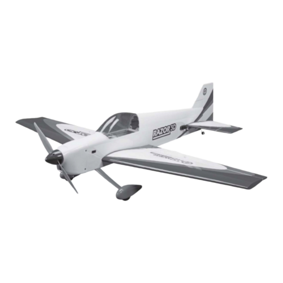
54.5 in [1385mm]
®
Hobbies
guarantees
this kit to be
free from defects
in both material and
workmanship
at
the
date of purchase. This
warranty does not cover any
component parts damaged by
use or modification. In no case
shall Tower Hobbies' liability exceed
the original cost of the purchased kit.
Further, Tower Hobbies reserves the right to
change or modify this warranty without notice.
In that Tower Hobbies has no control over the final
assembly or material used for final assembly, no
liability shall be assumed nor accepted for any damage
resulting from the use by the user of the final
user-assembled
product.
user-assembled product, the user accepts all resulting liability.
If the buyer is not prepared to accept the liability associated with the
use of this product, the buyer is advised to return this kit immediately in
new and unused condition to the place of purchase.
To make a warranty claim send the defective part or item to Hobby Services at
the address below:
Include a letter stating your name, return shipping address, as much contact information
as possible (daytime telephone number, fax number, e-mail address), a detailed description
problem will be evaluated as quickly as possible.
LENGTH
WING AREA
5 – 5.5 lb [2270 – 2490 g]
By
the
act
of
using
the
M A N U A L
WINGSPAN
52 in [1320mm]
579 sq in [37.3 dm
]
2
WEIGHT
.46 –.55 cu in [7 .5 – 9cc] two-stroke engine,
.70 –.81 cu in [11.5 –13.5cc] four-stroke engine,
RimFire .55 (42-60-480) brushless out-runner motor
READ THROUGH THIS MANUAL
BEFORE STARTING CONSTRUCTION.
IT CONTAINS IMPORTANT INSTRUCTIONS
AND WARNINGS CONCERNING THE
ASSEMBLY AND USE OF THIS MODEL.
™
WING LOADING
20 – 22 oz/sq ft [61 – 67 g/dm
RADIO
4-channel minimum with 4-5 servos
and standard size receiver
ENGINE / MOTOR
TOWER HOBBIES
Entire Contents
© 2011 Tower Hobbies
TOWA2055MNL V1.0
]
2
Advertisement
Table of Contents

Subscribe to Our Youtube Channel
Related Manuals for Tower Hobbies Razor 3D


Summary of Contents for Tower Hobbies Razor 3D
-
Page 1: Tower Hobbies
Further, Tower Hobbies reserves the right to RimFire .55 (42-60-480) brushless out-runner motor change or modify this warranty without notice. In that Tower Hobbies has no control over the final assembly or material used for final assembly, no READ THROUGH THIS MANUAL liability shall be assumed nor accepted for any damage BEFORE STARTING CONSTRUCTION. -
Page 2: Table Of Contents
Charge The Batteries ......25 1. Your Razor 3D ARF should not be considered a toy, but rather Balance Propellers . -
Page 3: Decisions You Must Make
If you are installing a glow engine, choose a prop based on the engine manufacturer’s recommendation. If you are installing This is a partial list of items required to fi nish the Razor 3D ARF the recommended RimFire brushless motor, we suggest a that may require planning or decision making before starting to 14 ×... -
Page 4: Additional Items Required
This is the list of hardware and accessories required to fi nish the ■ AccuThrow ™ Defl ection Gauge (GPMR2405) Razor 3D ARF. Order numbers are provided in parentheses: ■ CG Machine™ (GPMR2400) ■ Hobbico Flexible 18" Ruler Stainless Steel (HCAR0460) ■ R/C foam rubber (1/4" [6mm] - HCAQ1000, or 1/2"... -
Page 5: Important Building Notes
■ Photos and sketches are placed before the step they refer Tower Hobbies Product Support to. Frequently you can study photos in following steps to get 3002 N Apollo Drive, Suite 1 another view of the same parts. -
Page 6: Ordering Replacement Parts
ORDERING REPLACEMENT PARTS Replacement parts for the Razor 3D ARF are available from Tower Hobbies or Hobby Services using the order numbers in the Replacement Parts List that follows. Contact Tower at www.towerhobbies.com, or call toll free (800) 637-6050. Contact Hobby Services by calling (217) 398-0007, or via facsimile at (217) 398-7721. -
Page 7: Install The Aileron Servos And Pushrods
INSTALL THE AILERON SERVOS AND PUSHRODS ❏ 2. Test fi t a CA hinge into each of the hinge slots in the wing and ailerons. If necessary, enlarge the slots with a hobby knife. When satisfi ed with the fi t, insert a CA hinge halfway into each ❏... - Page 8 CORRECT INCORRECT ❏ 3. Position the servos in the aileron servo bays in the Hinge Line Hinge Line orientation shown. Drill 1/16" [1.6mm] holes through the servo mounting tabs. Thread a servo mounting screw (included with the servos) into each hole and back it out. Apply a drop of thin CA to each hole to harden the wood.
-
Page 9: Finish The Wing
FINISH THE WING to each hole to harden the wood surrounding the holes. When the glue has cured, install the control horns onto the ailerons using four 2-56 x 1/2" [13mm] machine screws and control horn backplates. ❏ 1. Use epoxy to glue the nylon wing dowels into the center LE of the wing. -
Page 10: Build The Fuselage
❏ 5. Trim the covering away from the gluing edges of the belly pan. ❏ ❏ 6. Reinstall the wing onto the fuse (we recommend lining the 4. Remove the belly pan from the wing and the wing from LE and TE of the wing between it and the fuse with wax paper the fuse. - Page 11 Measure from the wing tips to the stab tips and make those distances equal. Wipe away excess epoxy with paper towels dampened with denatured alcohol. Confi rm that the stab and wing are still parallel. A weight can be added to one side of the stab to make any small corrections.
-
Page 12: Assemble And Install The Landing Gear
ASSEMBLE AND INSTALL THE LANDING GEAR ❏ ❏ 5. Glue the vertical fi n into the slot using thin CA. 1. Secure the axles to the landing gear legs using the 5/16"- 24 nylon lock nuts. ❏ 2. Slide a 5/32" [4mm] wheel collar onto each axle followed by a 2-1/2"... -
Page 13: Install The Tail Servos And Pushrods
INSTALL THE TAIL SERVOS AND PUSHRODS ❏ 1. Attach a 24" [610mm] servo extension to the rudder and elevator servos. ❏ 4. Attach the wheel pants to the landing gear legs using four 2-56 x 3/8" [9.5mm] machine screws, four #2 fl at washers, four ❏... -
Page 14: Glow Engine Installation
fi ll line. The Razor 3D ARF is designed to be fl own with a .46-.55 If installing a fi ll line, puncture the top of the stopper above the two-stroke glow engine, .70-.81 four-stroke glow engine, or a... - Page 15 ❏ 6. If you are installing the O.S. FS81-a engine, you will need to trim away the nose gear bearing on the top side of the engine mount as shown. A rotary tool works well for this. ❏ 4. Make a 10" [254mm] long strap from the included hook and loop material by overlapping the mating ends by approximately 1"...
- Page 16 ❏ 10. Loosely thread a 4-40 set screw into the brass screw- lock pushrod connector. Install the screw-lock connector on the ❏ 8. Mark the location of the engine mount holes onto the underside of the outer hole in the throttle servo arm using a mount rails using a Dead Center Hole Locator.
- Page 17 ❏ 13. Insert the pushrod through the outer pushrod tube and through the screw-lock pushrod connector on the throttle servo arm. Connect the clevis to the throttle arm on the carburetor. Make any necessary bends in the pushrod so the pushrod can actuate the throttle without binding.
-
Page 18: Brushless Motor Installation
BRUSHLESS MOTOR INSTALLATION The Razor 3D ARF is designed to be fl own with a .46-.55 two-stroke glow engine, .52-.81 four-stroke glow engine, or a brushless out-runner motor. If you have installed a glow engine, skip this section as it only contains information relevant to installing a brushless motor. - Page 19 ❏ 6. Glue the ESC tray side pieces to the tray in the orientation shown. Be sure the side pieces are thoroughly glued. ❏ 9. Connect the motor lead wires to the ESC. Wrapping the wires behind the ESC tray below the mount will keep the excess length neatly out of the way.
-
Page 20: Install The Receiver, Battery Pack And Switch Harness
INSTALL THE RECEIVER, BATTERY PACK your battery packs. Apply a thin coat of epoxy to the battery tray and let it cure undisturbed. The epoxy will improve the AND SWITCH HARNESS adhesion of the self-adhesive hook and loop material. Cut a piece of the hook side from a package of self-adhesive hook and loop material (not included) and apply it to the center of the battery tray. -
Page 21: Finish The Model
FINISH THE MODEL ❏ 1. Before fi tting the cowl, make any cutouts necessary for your power system. If you have installed a glow engine, a cutout must be made for the exhaust, needle valve access, glow plug access, and cool air exit. A rotary tool such as a Dremel works very well for cutting holes in fi... - Page 22 ❏ 6. Install your propeller using the prop washer and nut that came with the motor. Enlarge the propeller slots in the spinner cone as necessary to fi t over the propeller blades. When satisfi ed, install the spinner cone onto the backplate using the provided screws.
-
Page 23: Apply The Decals
BATTERY PRECAUTIONS This is how to connect four batteries in Series: These are four 11.1 V, 3200mAh batteries. When joined in Series, the result will be a 44.4 V, 3200mAh battery. OKAY These are Series adapters that ❏ 8. You have now completed the assembly! connect two batteries in Series. -
Page 24: Check The Control Directions
SET THE CONTROL THROWS NEVER connect batteries that have different capacities! NO!! Different Capacities CHECK THE CONTROL DIRECTIONS Use a Great Planes AccuThrow (or a ruler) to accurately measure and set the control throw of each control surface as indicated in ❏... -
Page 25: Balance The Model (C.g.)
❏ 3. If the tail drops, the model is “tail heavy” and the battery IMPORTANT: The Razor 3D ARF has been extensively pack and/or receiver must be shifted forward or weight must fl own and tested to arrive at the throws at which it fl ies be added to the nose to balance. -
Page 26: Balance Propellers
ENGINE SAFETY PRECAUTIONS ––––––– CAUTION: Unless the instructions that came with your radio system state differently, the initial charge on new FAILURE TO FOLLOW THESE SAFETY PRECAU- transmitter and receiver batteries should be done for 15 TIONS MAY RESULT IN SEVERE INJURY TO hours using the slow-charger that came with the radio YOURSELF AND OTHERS. -
Page 27: Ama Safety Code (Excerpts)
CHECK LIST –––––––––––––––––––––––––––– ■ NEVER disassemble or modify pack wiring in any way or puncture cells. ■ NEVER discharge below 2.5V per cell. During the last few moments of preparation your mind may ■ NEVER place on combustible materials or leave be elsewhere anticipating the excitement of the fi... -
Page 28: Flying
FLYING ––––––––––––––––––––––––––––––––– FLIGHT The Razor 3D ARF is a great-fl ying model that fl ies smoothly For reassurance and to keep an eye on other traffi c, it is a good idea and predictably. The Razor does not, however, possess the self- to have an assistant on the fl...
Need help?
Do you have a question about the Razor 3D and is the answer not in the manual?
Questions and answers