Advertisement
Available languages
Available languages
HOT WATER BOILER
INSTALLER / SERVICE TECHNICIAN:
USE THE INFORMATION IN THIS MANUAL FOR THE INSTALLATION AND
SERVICING OF THE FURNACE AND KEEP THE DOCUMENT NEAR THE
UNIT FOR FUTURE REFERENCE.
HOMEOWNER:
PLEASE KEEP THIS MANUAL NEAR THE FURNACE FOR FUTURE
REFERENCE.
Printed in Canada
Printed on 100% recycled paper
OIL FIRED
HMT
HM2
HMR
Caution: Do not tamper with
the unit or its controls. Call a
qualified service technician.
Manufactured by:
DETTSON INDUSTRIES INC.
3400 Industrial Boulevard
Sherbrooke, Quebec – Canada - J1L 1V8
www.dettson.ca
2011-07-06
Models :
HMR
HMT
HM2
X40019 Rev. AB
Advertisement
Table of Contents

Related Manuals for Dettson HMR


Summary of Contents for Dettson HMR
- Page 1 USE THE INFORMATION IN THIS MANUAL FOR THE INSTALLATION AND SERVICING OF THE FURNACE AND KEEP THE DOCUMENT NEAR THE Manufactured by: UNIT FOR FUTURE REFERENCE. DETTSON INDUSTRIES INC. 3400 Industrial Boulevard HOMEOWNER: Sherbrooke, Quebec – Canada - J1L 1V8 PLEASE KEEP THIS MANUAL NEAR THE FURNACE FOR FUTURE www.dettson.ca...
-
Page 3: Unit Identification
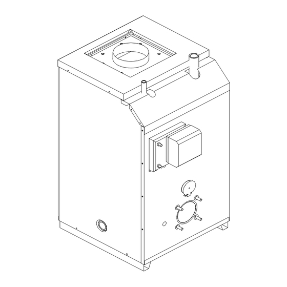
1.2) UNIT IDENTIFICATION It is very important that you consult Figures 1 to 3 to identify the characteristics of each of the models offered in the “HMR - HMT – HM2” series. Figure 1: “HMR” boilers without sanitary hot water coil and with a 13 cm (5") flue-pipe. -
Page 4: Oil Supply
Each of these boilers has its own characteristics: location of return and “HMR – HMT – HM2” boilers with integrated by-pass are designed for supply pipes, sanitary hot water coil, relief valve and thermo installation on any type of distribution (piping) system that is equipped manometer, diameter of the flue-pipe, etc. - Page 5 1.7.3) Side wall venting The satisfactory operation of your boiler depends greatly on the “HMR-HMT-HM2” hot water boilers are approved for installation with installation of your plumbing. Refer to Figure 4. the SMH side wall venting system. HMT hot water boiler is also In any event, the installation must include: approved for installation with the VTK sealed combustion system.
-
Page 6: Part 2 Operation
1.14) THERMOSTAT 1.13) SANITARY HOT WATER HEATING COIL The thermostat must be mounted on an inside wall, approximately Before attempting to install a coil, always check the water quality to 1.5 m (5') above the floor. The location should be such that the avoid premature scaling, which quickly renders your installation thermostat is not subjected to air currants and/or exposed to direct inefficient. -
Page 7: Part 3 Maintenance
PART 3 MAINTENANCE 3.1) MAINTENANCE 3.7) BLOCKED VENT SHUT-OFF (BVSO) CLEANING The area around the boiler must be kept free of combustibles, excessive dust and humidity, and highly flammable products at all For continued safe operation, the Blocked Vent Shut-Off System times. - Page 8 PART 4 INFORMATION Model: Serial number: Installation date of the boiler: Service telephone # - Day: Night : Dealer name and address : START-UP TEST RESULTS Nozzle: Pressure : lb/in Burner adjustments : Primary air Fine air Draw Assembly Smoke scale : (Bacharach) Gross flue temperature: °F...
- Page 9 TABLE 2 Technical specifications HMR Beckett Burner AFG-F HMR-80-B HMR-92-B HMR-103-B HMR-121-B Capacity (BTU/h) 79000 90000 101000 116000 Input (USGPH) 0.65 0.75 0.85 1.00 Retention head LFRB* Nozzle (Delavan) 0.65-80W 0.75-80W 0.85-80W 1.00-80A Pressure (PSI) Insertion tube (in.) 2 7/8...
- Page 10 TABLE 3 Technical specifications HMT Beckett Burner AFG-F HMT-12-B HMT-14-B HMT-16-B HMT-18-B (With chim ney) Capacity (BTU/h) 118000 141000 158000 175000 Input (USGPH) 1.00 1.20 1.35 1.50 Retention head LFRB* Nozzle (Delavan) 1.00-70A 1.20-70A 1.35-70A 1.50-70A Pressure (PSI) Insertion tube (in.) 2 7/8 2 7/8 2 7/8...
- Page 11 TABLE 4 Technical specifications HM2 HM-185-B HM-212-B HM-240-B HM-266-B HM-293-B Beckett Burner AFG-V1 Capacity (BTU/h) 185000 215000 243000 270000 296000 Input (USGPH) 1.50 1.75 2.00 2.25 2.50 Retention head MD-V1 MD-V1 MD-V1 MD-V1 MD-V1 LFRB* Nozzle (Delavan) 1.50-70B 1.75-70B 2.00-70B 2.25-70B 2.50-70B Pressure (PSI)
- Page 12 FIGURE 1 HMR Boiler DNS-0317 Rev. B FIGURE 2 HMT boiler with or without coil DNS-0321 Rev. C...
- Page 13 FIGURE 3 HM2 boiler with or without coil DNS-0320 Rev. B...
- Page 14 FIGURE 4 General piping installation diagram DNS-0523 Rev. B...
- Page 15 FIGURE 5.1 Typical connection without sanitary water coil Control used: “Triple action” temperature control - Honeywell # L6081A or White Rodgers # 11C61 (Aquastat Triple, Hi-Lo/Circ) DNS-0144 Rev. H Operation and typical settings Operation: Burner Stop Thermostat opened -or- “Hi” contact opened Start Thermostat closed -and- “Hi”...
- Page 16 FIGURE 5.2 Typical connection for system with finned tube radiators and without sanitary water coil Control used: - “Triple action” temperature control -Honeywell # L6081A or White Rodgers # 11C61 (Aquastat Triple, Hi-Lo/Circ) - Pump relay Honeywell # RA89A or White Rodgers # 809A DNS-0145 Rev.
- Page 17 FIGURE 5.3 Typical connection with or without sanitary water coil Control used: “Triple relay Multizone” temperature control Honeywell # L8124L1029B DNS-0943 Rev. C Operation and typical settings Operation: Burner Stop "Hi" contact opened -or- if Thermostat opened, "Lo" contact opened Start "Hi"...
- Page 18 FIGURE 5.4 Typical connection with or without sanitary water coil Control used: Triple relay temperature control Honeywell # L8124L1102B DNS-0146 Rev. C Operation and typical settings Operation: Burner Stop "Hi" contact opened -or- if Thermostat opened, "Lo" contact opened Start "Hi"...
- Page 19 FIGURE 5.5 Typical connection with or without sanitary water coil Control used: - “Triple action” temperature control Honeywell # L6081A or White Rodgers # 11C61 (Aquastat Triple, Hi-Lo/Circ) - Pump relay Honeywell # RA89A or White Rodgers # 809A DNS-0147 Rev. G Operation and typical settings Operation: Burner...
-
Page 20: Parts List
PARTS LIST Model : HMR (HM-080 @ HM-103) B50019B... - Page 21 PARTS LIST Model : HMR (HM-080 @ HM-121) ITEM PART # DESCRIPTION B 00472-01 FLOOR B 0061 9-01 FLOOR INSULA TION B 0061 8-01 COM B USTION CHA M B ER B OTTOM INSULA TION F03F004 FLOOR SCREW (Quantity: 4)
- Page 22 PARTS LIST Model : HMT (HMT-12 @ HMT-18) S/N greater than D010408972 B50020B...
-
Page 23: Front Top P A Nel
PARTS LIST Model : HMT (HMT-12 @ HMT-18) S/N greater than D010408972 ITEM PART # DESCRIPTION B 02349-01 HEA T EXCHA NGER (Witho ut co il) B 01 91 0 HEA T EXCHA NGER OUTER INSULA TION G08F004 REDUCER B USHING 1 " x 1 /2" B LA CK G1 1 Z001 DRA IN FA UCET 1 /2"... - Page 24 PARTS LIST Model : HM2 (HM-185 @ HM-293) S/N greater than D010408972 B50021B...
- Page 25 PARTS LIST Model : HM2 (HM-185 @ HM-293) S/N greater than D010408972 ITEM PART # DESCRIPTION B 00989 HEA T EXCHA NGER B 0061 8-04 COM B USTION CHA M B ER B OTTOM INSULA TION B 0061 9-03 FLOOR INSULA TION B 00472-03 FLOOR F03F004...
- Page 26 POUR L’INSTALLATION ET L’ENTRETIEN DE L’APPAREIL ET GARDER LE Fabriqué par : DOCUMENT PRÈS DE L’UNITÉ POUR RÉFÉRENCES ULTÉRIEURES. INDUSTRIES DETTSON INC. PROPRIÉTAIRE : 3400, boulevard Industrie Sherbrooke, Québec – Canada – J1L 1V8 S.V.P. GARDEZ CE MANUEL PRÈS DE L’UNITÉ POUR RÉFÉRENCES www.dettson.ca...
-
Page 28: Section 1 Installation
SECTION 1 INSTALLATION 1.1) LIBELLE DE SÉCURITÉ ET SIGNALISATION DANGER, MISE EN GARDE ET AVERTISSEMENT MISE EN GARDE Comprenez bien la portée des mots suivant : DANGER, MISE EN GARDE ou AVERTISSEMENT. Ces mots sont associés aux symboles • Cette chaudière a été conçue pour vous assurer de sécurité. - Page 29 “HMR - HMT – HM2 ”. respectant les règlements des autorités compétentes et le “Code Figure 1: Chaudière “HMR” sans serpentin et avec tuyau à Canadien de l’Électricité - CSA C22.1 / Partie I” fumée de 13 cm (5"). Modèles identifiés HMR-080, HMR-092 et HMR-103.
- Page 30 1.7.3) Évacuation murale Raccorder le(s) tuyau(x) de mazout à la pompe du brûleur ; Les chaudières “HMR-HMT-HM2” sont approuvées avec le système Faire le raccordement électrique selon le schéma approprié. Voir d'évacuation murale des gaz de combustion “SMH”. La chaudière paragraphe 1.5.
- Page 31 1.11) TUYAUTERIE 1.12) VÉRIFCATION DU DISPOSITIF D'ARRÊT ANTI-REFOULEMENT Le bon fonctionnement de votre système à l'eau chaude dépend pertinemment de votre installation de plomberie. Consulter la figure 4. Cette vérification sert à valider le bon fonctionnement de la prise BVSO sur l'unité de chauffage seulement. Dans tous les cas, votre installation doit comprendre : Faire fonctionner le brûleur ;...
-
Page 32: Section 2 Opération
SECTION 2 OPÉRATION Nous recommandons que l'entretien et la mise en Note : Si votre brûleur est muni d'un cabinet de marche de votre chaudière soient effectués par un brûleur, faire tous les tests de combustion avec ce cabinet en place. Ne pas oublier de technicien qualifié... -
Page 33: Section 3 Entretien
SECTION 3 ENTRETIEN 3.1) ENTRETIEN 3.7) NETTOYAGE DU DISPOSITIF D’ARRÊT ANTI-REFOULEMENT (BVSO) Maintenir en tout temps les environs immédiats de la chaudière, libres de tous matériaux combustibles de poussière excessive, d’humidité Pour un fonctionnement continu et sûr, le dispositif d’arrêt doit être excessive et de produits hautement inflammables. - Page 34 SECTION 4 INFORMATION Modèle : Numéro de série : Date d’installation de la chaudière : Nos tél. service – Jour : Soir : Nom et adresse du technicien de service : RÉSULTAT DU TEST DE MISE EN MARCHE Gicleur : Pression : lb/po Ajustements du brûleur :...
- Page 35 TABLEAU 2 Spécifications techniques HMR Bruleur Beckett AFG-F HMR-80-B HMR-92-B HMR-103-B HMR-121-B Capacité (BTU/h) 79000 90000 101000 116000 Entrée (USGPH) 0.65 0.75 0.85 1.00 Tête de rétention LFRB* Gicleur (Delavan) 0.65-80W 0.75-80W 0.85-80W 1.00-80A Pression (PSI) Tube d'insertion (po.) 2 7/8...
- Page 36 TABLEAU 3 Spécifications techniques HMT Bruleur Beckett AFG-F HMT-12-B HMT-14-B HMT-16-B HMT-18-B (Avec chem inée) Capacité (BTU/h) 118000 141000 158000 175000 Entrée (USGPH) 1.00 1.20 1.35 1.50 Tête de rétention LFRB* Gicleur (Delavan) 1.00-70A 1.20-70A 1.35-70A 1.50-70A Pression (PSI) Tube d'insertion (po.) 2 7/8 2 7/8 2 7/8...
- Page 37 FIGURE 1 Chaudière HMR DNS-0317 Rév. B FIGURE 2 Chaudière HMT avec ou sans serpentin DNS-0321 Rév. C...
- Page 38 FIGURE 3 Chaudière HM2 avec ou sans serpentin DNS-0320 Rév. B...
- Page 39 FIGURE 4 Schéma typique recommandé d’un installation général de la tuyauterie DNS-0523 Rév. B...
- Page 40 FIGURE 5.1 Raccordement typique sans serpentin d’eau sanitaire Contrôleur utilisé: Limiteur de température à “triple action” Honeywell # L6081A ou White Rodgers # 11C61 (Aquastat Triple, Hi-Lo/Circ) DNS-0144 Rév. H Fonctionnement et ajustements typiques Fonctionnement : Brûleur Arrêt Thermostat ouvert -ou- Contact “Hi” ouvert Départ Thermostat fermé...
- Page 41 FIGURE 5.2 Raccordement typique sur système avec convecteurs à ailettes et sans serpentin d’eau sanitaire Contrôleur utilisé: - Limiteur de température à “triple action” Honeywell # L6081A ou White Rodgers # 11C61 (Aquastat Triple, Hi-Lo/Circ) - Relais de pompe circulatoire Honeywell # RA89A ou White Rodgers # 809A DNS-0145 Rév.
- Page 42 FIGURE 5.3 Raccordement typique avec ou sans serpentin d’eau sanitaire Contrôleur utilisé: Limiteur de température à triple relais "Multizone" Honeywell # L8124L1029B DNS-0943 Rév. BC Fonctionnement : Brûleur Arrêt Contact "Hi" ouvert -ou- si Thermostat ouvert, contact "Lo" ouvert Départ Contact "Hi"...
- Page 43 FIGURE 5.4 Raccordement typique avec ou sans serpentin d’eau sanitaire Contrôleur utilisé: Limiteur de température à triple relais Honeywell # L8124C1102B DNS-0146 Rév. C Fonctionnement et ajustements typiques Fonctionnement : Brûleur Arrêt Contact "Hi" ouvert -ou- si Thermostat ouvert, contact "Lo" ouvert Départ Contact "Hi"...
- Page 44 FIGURE 5.5 Raccordement typique avec ou sans serpentin d’eau sanitaire Contrôleur utilisé: - Limiteur de température à “triple action” Honeywell # L6081A ou White Rodgers # 11C61 (Aquastat Triple, Hi-Lo/Circ) - Relais de pompe circulatoire Honeywell # RA89A ou White Rodgers # 809A DNS-0147 Rév.
-
Page 45: Liste De Pièces
LISTE DE PIÈCES Modèle : HMR (HM-080 @ HM-103) B50019B... - Page 46 LISTE DE PIÈCES Modèle : HMR (HM-080 @ HM-103) ITEM No. DESSIN DESCRIPTION B 00472-01 PLA NCHER B 0061 9-01 ISOLA TION P LA NCHER B 0061 8-01 ISOLA TION DE FOND DE CHA M B RE A COM B USTION F03F004 VIS A P LA NCHER (Quantité...
- Page 47 LISTE DE PIÈCES Modèle : HMT (HMT-12 @ HMT-18) S/N plus grand que D010408972 B50020B...
- Page 48 LISTE DE PIÈCES Modèle : HMT (HMT-12 @ HMT-18) S/N plus grand que D010408972 ITEM No. DESSIN DESCRIPTION B 02349-01 A SS CHA UDIERE EA U CHA UDE (sans serpentin) B 01 91 0 ISOLA TION CA B INET G08F004 DOUILLE REDUCTRICE 1 "...
- Page 49 LISTE DE PIÈCES Modèle : HM2 (HM-185 @ HM-293) S/N plus grand que D010408972 B50021B...
- Page 50 LISTE DE PIÈCES Modèle : HM2 (HM-185 @ HM-293) S/N plus grand que D010408972 ITEM No. DESSIN DESCRIPTION B 00989 A SS CHA UDIERE EA U CHA UDE B 0061 8-04 ISOLA TION DE FOND DE CHA M B RE A COM B USTION B 0061 9-03 ISOLA TON P LA NCHER B 00472-03...
Need help?
Do you have a question about the HMR and is the answer not in the manual?
Questions and answers